Considering the copyright issues surrounding color silkscreen printing on the CH582M development board, and the potential for resale and commercial use, I do not provide complete designs. I only provide copyright-free backgrounds or complete designs with watermarks. If you need color silkscreen printing, you'll need to find the images yourself, assemble them, and then place them on the PCB. Alternatively, you can obtain authorization from the respective copyright holders (artists or companies) and submit screenshots of the authorization to me. I can provide the original source files.
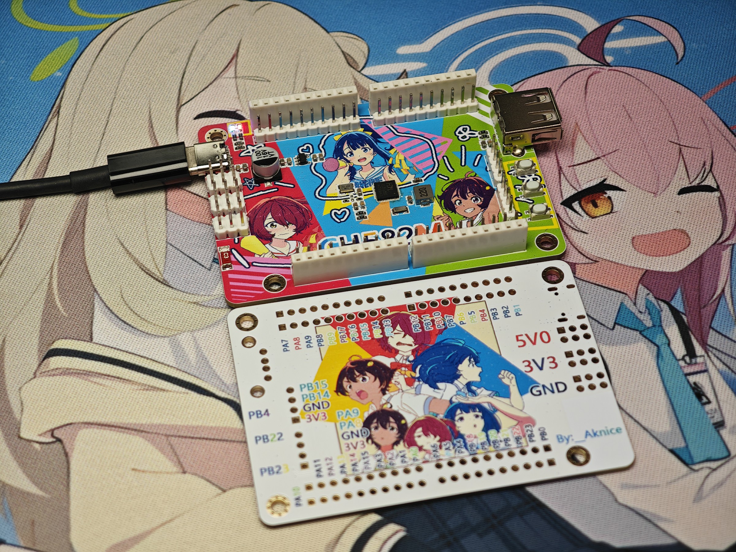
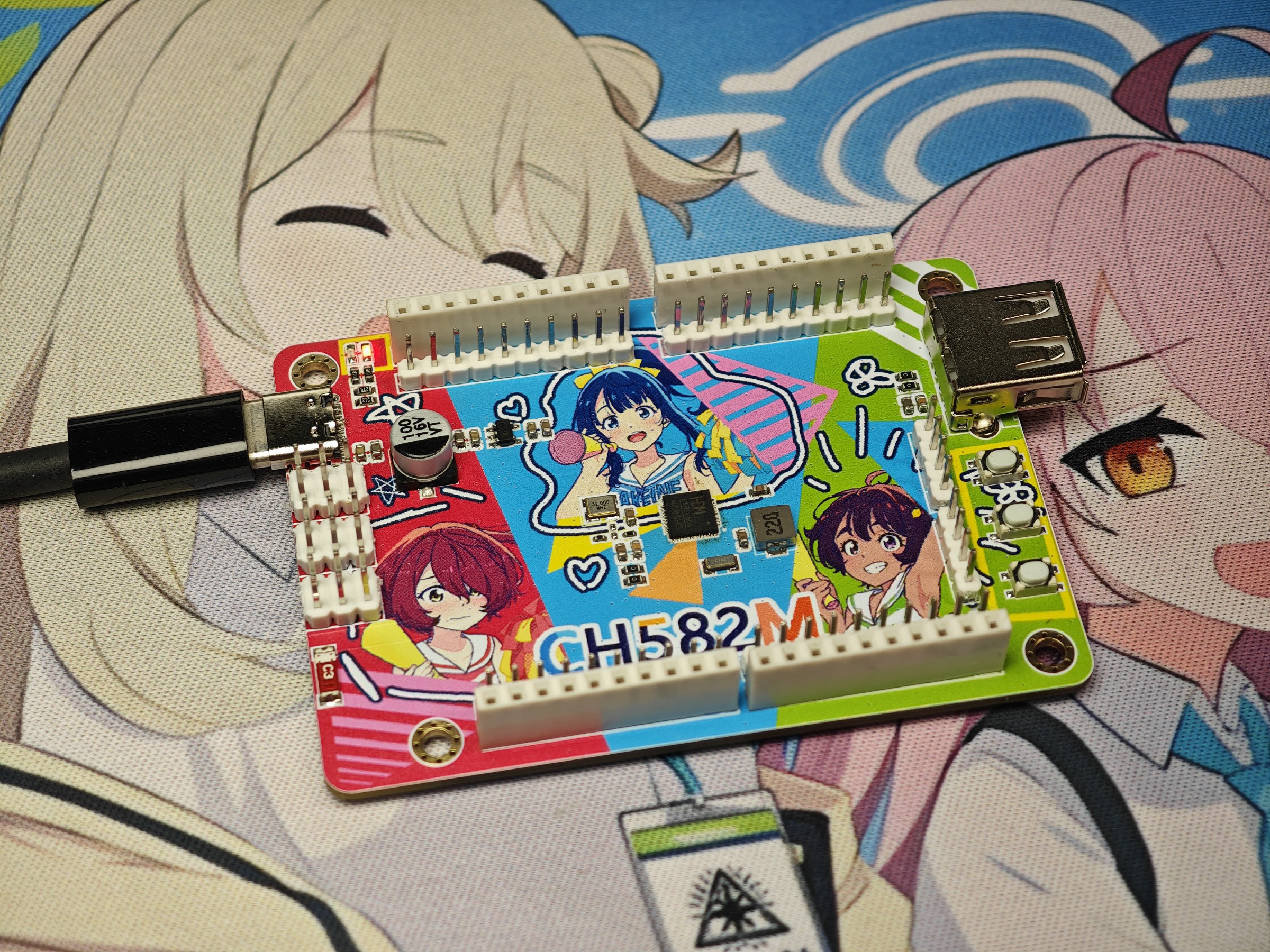
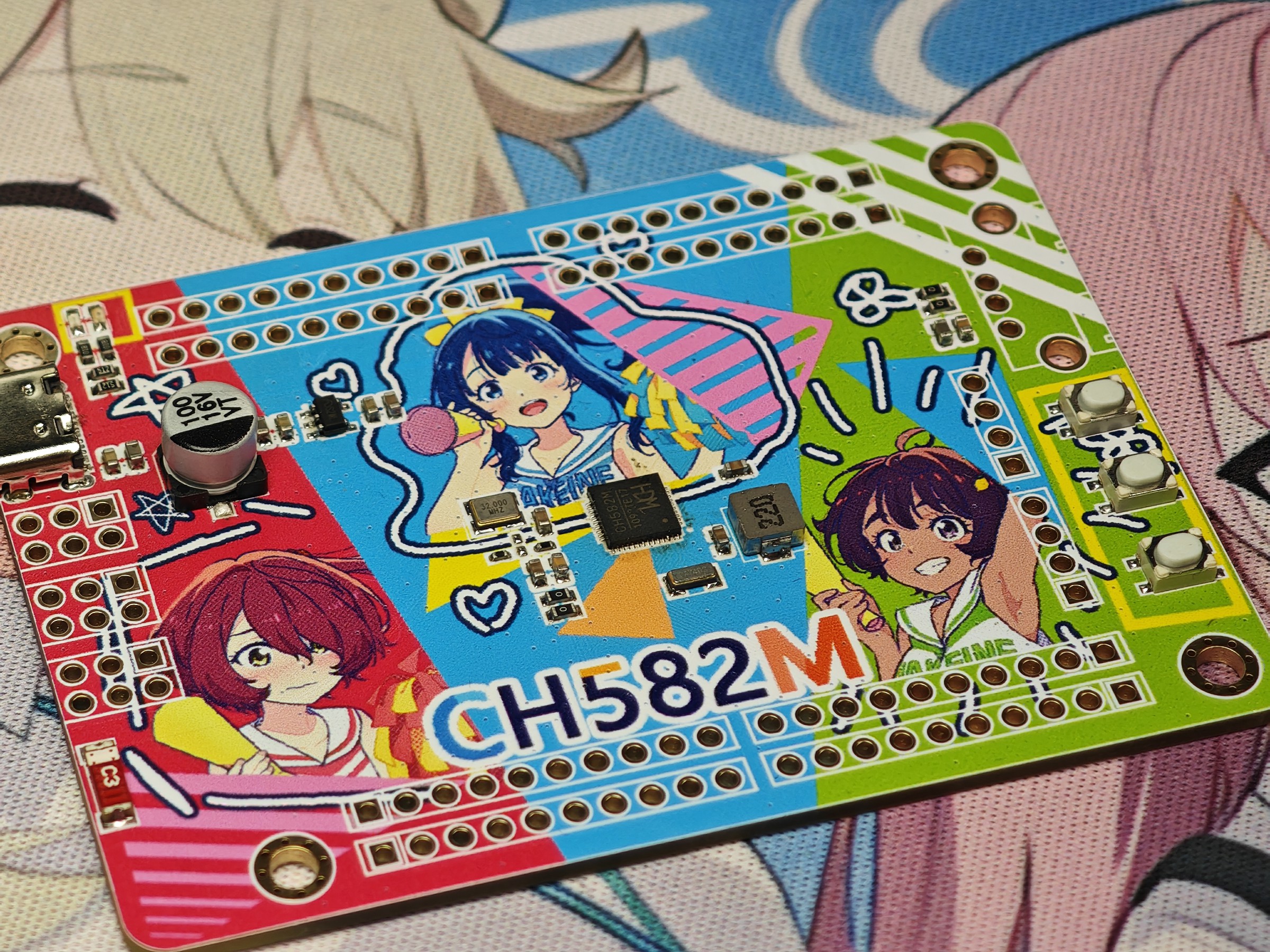
1. Color silkscreen printing: Front copyright
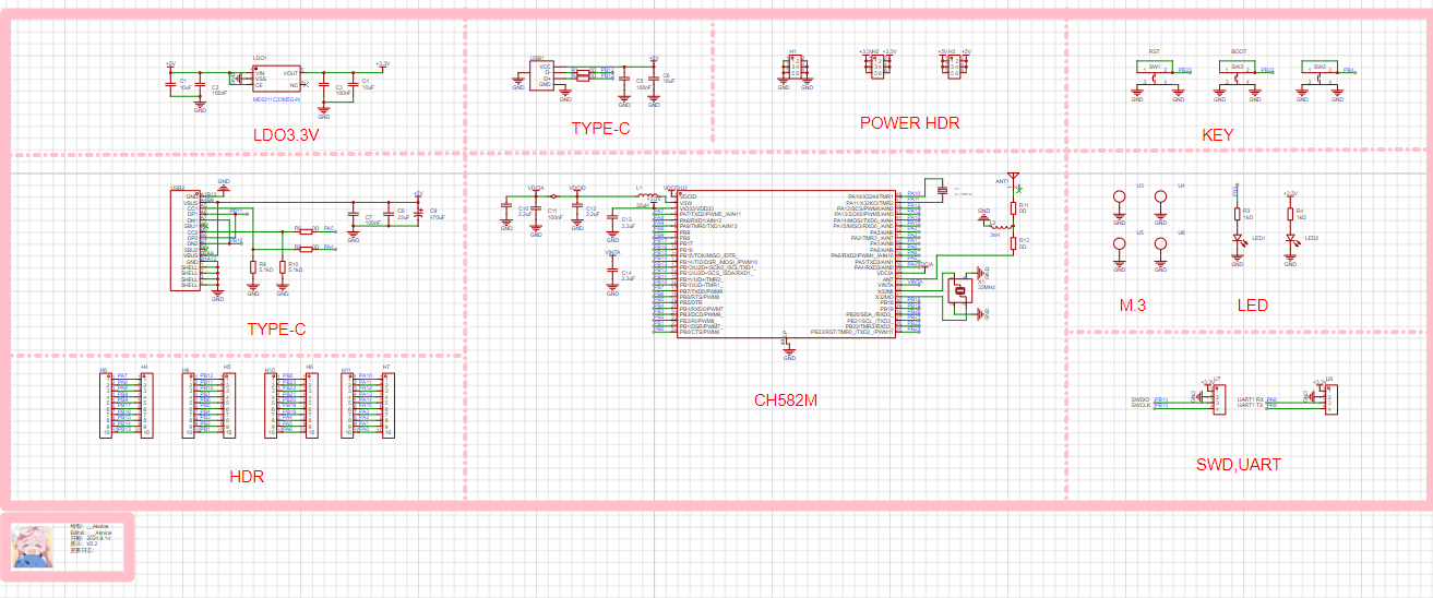
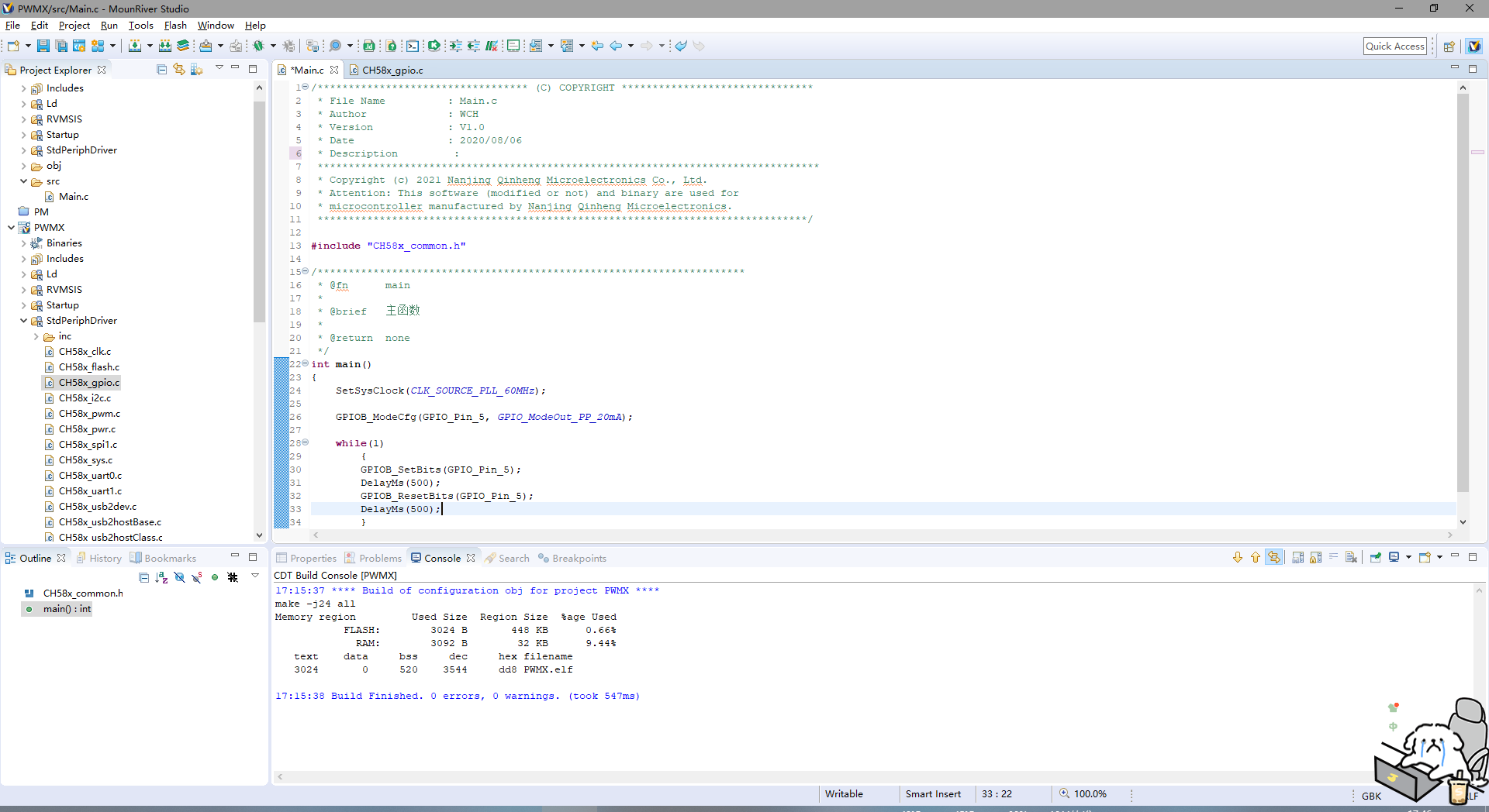
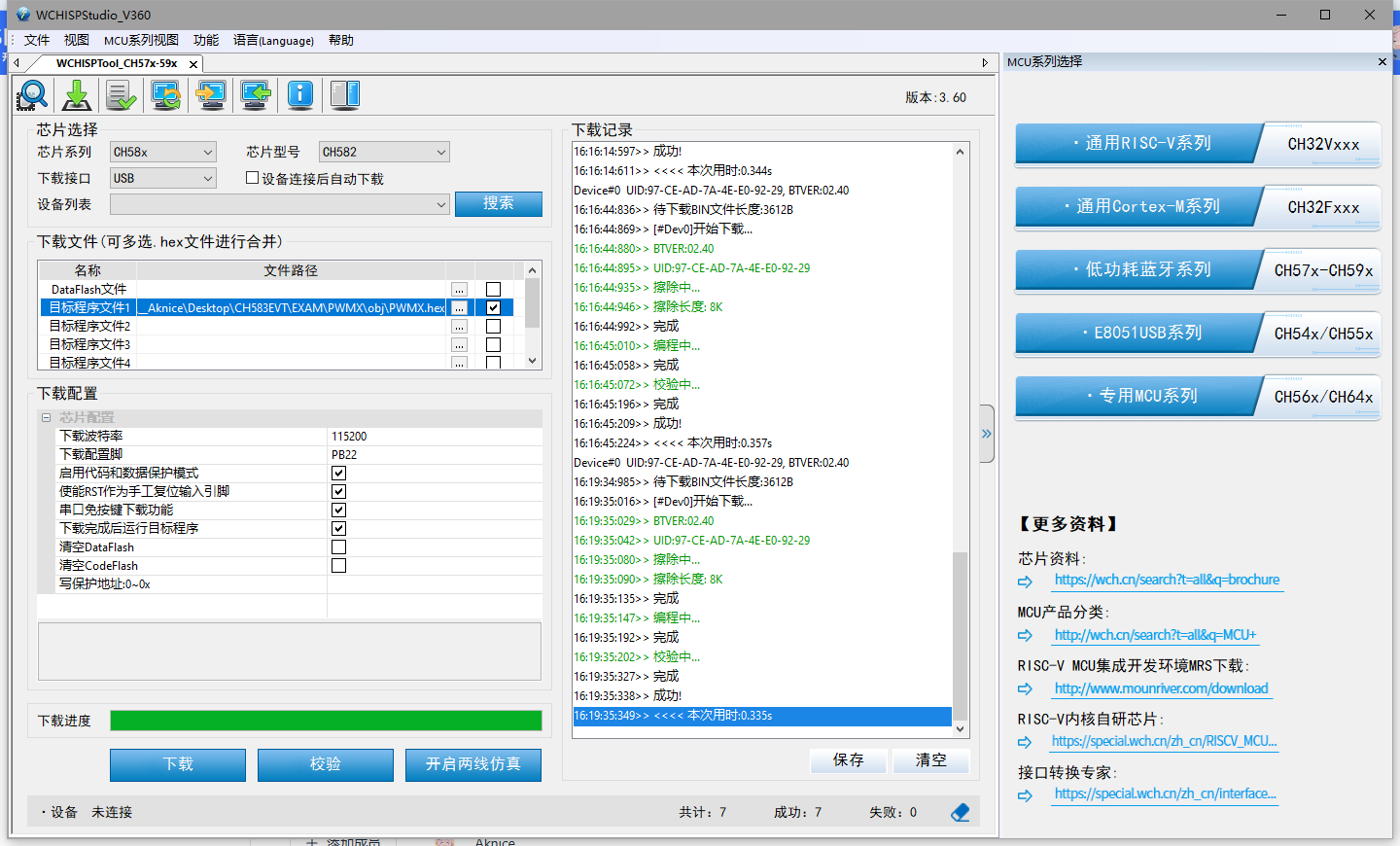
: Aniplex/雨森たきび/小学館/マケイン応援委員会; Back copyright: 暇人, pid:122084033 2. Schematic: CH582M minimum system schematic 3. Program : Modified official example using GPIO LEDs; PB5 uses the WCH official download tool. Press and hold PB22 while inserting the USB cable to enter download mode.
CH582M Color Silkscreen Printing. 7z
FPC Gold Finger Design Tutorial: https://www.jlc.com/portal/server_guide_43493.html
FPC Gold Finger Design Tutorial: https://www.jlc.com/portal/server_guide_43493.html
The chip adapter board used in the programmer allows for easy chip desoldering and resoldering without the need for a hot air gun or copper wire frame.
Are you still using the cheap adapter board that comes with the CH341A to program SOP8 chips? Are you still worried about the health hazards of hot air gun fumes during desoldering? Are you worried about burning the chips because you're too slow?
You should try this free solution: an adapter board that allows you to easily desolder SOP8 chips with a soldering iron. It's compatible with all SOP8, SOIC8, USON8, SOIC16, and SOT23-5 memory chips, including 24-series, 25-series, 93-series, and 11-series chips. Desoldering is as follows: simply press and bend the PCB while heating the pins. It's convenient, quick, reusable, inexpensive, and performs better than dedicated programming sockets. The result is shown in the picture:

the size is just right and won't protrude.

PDF_CH341A Programmer Flash Adapter Board EEPROM Adapter Board.zip
Altium CH341A programmer flash adapter board EEPROM adapter board. (zip)
PADS_CH341A Programmer Flash Adapter Board (EEPROM Adapter Board).zip
BOM_CH341A Programmer Flash Adapter Board EEPROM Adapter Board.xlsx
91909
ESP-Album
ESP-Album is a high-performance electronic photo album developed based on the Espressif ESP32-P4 chip. It can play photos, videos and music, and has three modes: manual switching, loop playback and random playback, providing a smooth multimedia playback experience.
Project Overview:
ESP-Album is a high-performance electronic photo album developed based on the Espressif ESP32-P4 chip. Leveraging the powerful image and audio/video processing capabilities of the ESP32-P4, this device can play photos, videos, and music, offering three modes: manual switching, loop playback, and random playback, providing users with a smooth multimedia playback experience.
All playback materials are stored on an SD card. ESP-Album supports WiFi wireless transmission and USB virtual flash drive functionality. via WiFi, users can instantly transfer photos from their mobile phones to the ESP-Album for display and storage on the SD card, while simultaneously viewing and saving existing materials on their mobile phones. The USB virtual flash drive function allows for easy data transfer between the computer and the ESP-Album.
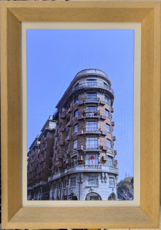
Combined with the excellent performance of the ESP32-P4, ESP-Album excels in processing power, connectivity, and energy efficiency, making it an ideal multimedia display solution for users. Physical Product Showcase
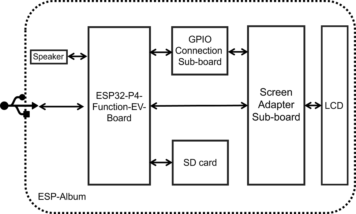
: ESP-Album Front View; Video Showcase : ESP32-P4 High-Definition Multifunctional Electronic Photo Frame. Creating this was no easy task, so please like, comment, and share! Project Features : Comprehensive Multimedia Playback Functions: Supports multiple playback modes for photos, videos, and music. Users can easily switch between different media playback types according to their personal preferences, enjoying a rich and diverse visual and auditory experience. Screen Brightness Adjustment Function: Features linear screen brightness adjustment. Long-press the left/right buttons on the back of the album to control screen dimming or brightening, achieving personalized settings to meet usage needs in different environments. Volume Adjustment Function: Control volume up and down by clicking or long-pressing the up/down/right buttons on the back of the album, providing a more comfortable volume control experience. Wireless Image Transmission Function: Supports Wi-Fi image transmission, allowing users to easily wirelessly transfer photos from their mobile phones to the ESP-Album and view and save existing images in the album in the file list. USB Virtual Drive Function: Supports USB virtual drive functionality. Connect the photo album to the computer via a data cable, and the computer will automatically pop up a USB drive, making it convenient to view, edit, delete, and add files in the photo album. Operation Logic Description Key Event Corresponding Functions Click OK button Play/Pause or Resume Click Up/Down button Volume + / Volume - Long press Up/Down button (Quick) Volume + / Volume - Click Left button / Down button Previous/Next Long press Left button / Down button Screen Brightness - / Screen Brightness + Click Mode Switch Key Switch between three playback modes in sequence Click Power button Screen off/on Hardware Description Overall Functional Framework The hardware system block diagram of ESP-Album is shown below: Hardware Components The hardware system consists of the following components: Main Control Unit: ESP32-P4-Function-EV-Board Screen Adapter Sub-board: Equipped with two FPC connectors for screen conversion and control Configuration of one FPC connector to connect GPIO control pins Integrated screen backlight control circuit to realize the display backlight adjustment function Equipped with seven touch buttons for logic control GPIO Connection Sub-board: Connects to the Screen Adapter Sub-board via FPC connector Equipped with *211P The female connector connects to the ESP32-P4-Function-EV-Board. Pin assignments and functions : GPIO 20 Up button , GPIO 22 Down button, GPIO 21 Left button , GPIO 23 Right button, GPIO 5 Confirm button , GPIO 4 Power button , GPIO 3 Playback mode switch button, GPIO 2 LCD backlight control . Power options: The ESP-Album currently only supports 5V Type-C interface power supply. Software specifications: Version information: ESP-IDF chip, SRAM (KB) , ROM (KB), PSRAM (MB) v5.3.1 , ESP32-P4NRW32 , 768 , 128, 32. Bill of materials: ESP32-P4-Function-EV-Board, 10.1-inch TFT display, 800*1280 resolution, MIPI interface, IPS full-view LCD screen. The frame needs to be customized. Attachments: 3D printing files and firmware will be included later. Please stay tuned!
PDF_ESP-Album.zip
Altium_ESP-Album.zip
PADS_ESP-Album.zip
BOM_ESP-Album.xlsx
91911
STC Temperature Detection System
STC8H108K is the temperature detection system with the main control chip.
This project is based on an STC temperature and humidity alarm, which has the function of detecting temperature.
This design is a temperature detection system based on STC8H1K08; when the temperature is higher than the set temperature, the fan works, and when the temperature is lower than the set temperature, the heater works.
Temperature detection.zip
September 29 (2).mp4
PDF_STC Temperature Detection System.zip
Altium_STC Temperature Detection System.zip
PADS_STC Temperature Detection System.zip
BOM_STC Temperature Detection System.xlsx
91912
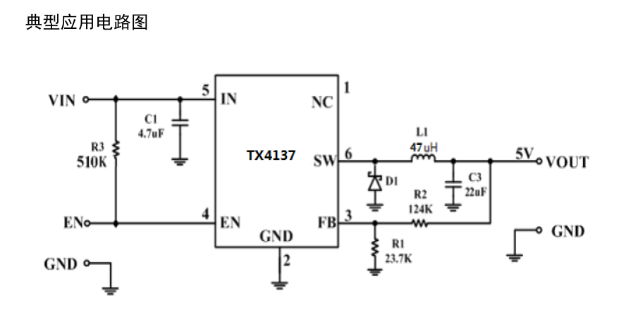
TX4137 DCDC Asynchronous Buck Demo
This project is a debug board for the TX4137 chip. The module supports an input voltage of 4.5-60V and an adjustable output voltage of 3.3V with a maximum output current of 0.6A.
Project Overview:
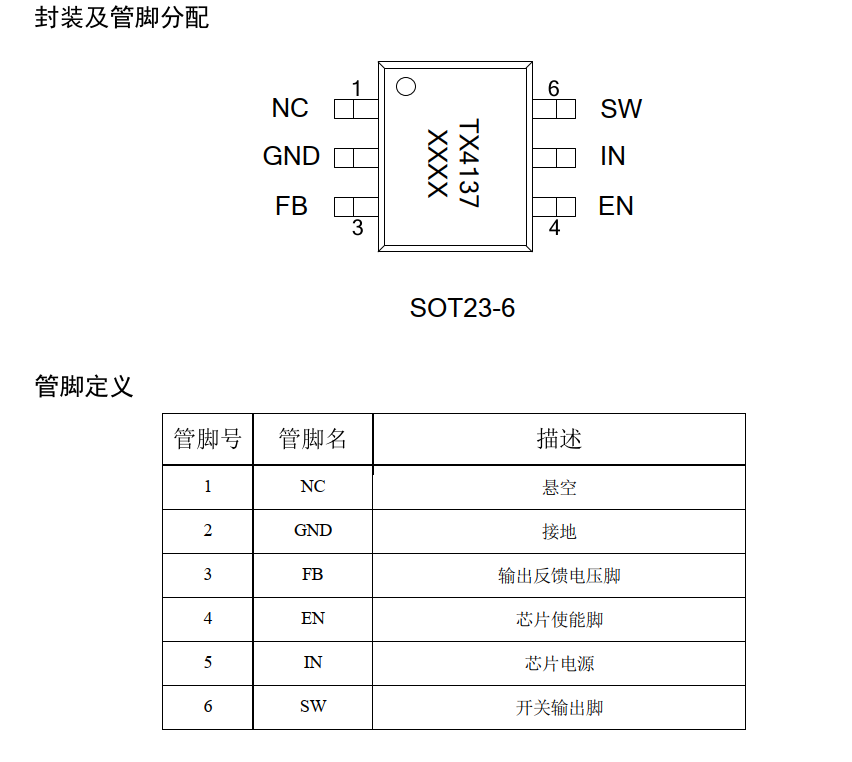
This project is a monolithic buck switch-mode converter using the TX4137 integrated power MOSFET. It achieves a peak output current of 0.6 A over a wide input power range of 5.5-60V, with excellent line voltage and load regulation. Utilizing PWM current-mode operation
, the loop is easily stabilized and provides fast transient response. Integrated protection functions include cycle-by-cycle current limiting and thermal shutdown. It employs an SOT23-6 package and requires minimal external components . Features include : SOT23-6 package and minimal external components; 0.6A peak output current ; 0.9Ω internal power MOSFET ; large output capacitor startup capability ; low ESR ceramic capacitor for stable output ; up to 90% efficiency ; fixed 500kHz frequency ; thermal shutdown ; cycle-by-cycle overcurrent protection ; wide input voltage range: 5.5~60V ; SOT23-6 package applications : electricity meters ; distributed power systems ; battery chargers ; and pre-regulator principle analysis (hardware description). The EN pin (enable pin) is used to enable the chip. It can be controlled by an external MCU. For applications where the enable pin is not used, it is pulled up to the IN pin by a resistor of approximately 510KΩ by default and cannot be left floating. The output voltage is set by the voltage divider resistors R1 and R2 connected to the FB pin. The feedback resistor (R2) also sets the bandwidth of the feedback loop through an internal compensation network. The values for R1 are as follows: Input Capacitor Values: The input capacitor is used to reduce the inrush current of the input power supply and suppress switching noise. At the switching frequency, the capacitive reactance of the input capacitor must be less than the impedance of the input source to prevent high-frequency switching current from flowing into the input terminal. Low ESR and low temperature coefficient ceramic capacitors X5R or X7R can be used; a value of 4.7μF is sufficient for most applications. For applications with higher input voltages, an electrolytic capacitor should be connected in parallel at the input terminal to suppress input voltage spikes during power-on and power-off. Output Capacitor Values: The output capacitor maintains a small output ripple voltage and ensures the stability of the feedback loop. At the switching frequency, the capacitive reactance of the output capacitor must be sufficiently small. Low ESR ceramic capacitors X5R or X7R can be used; a value of 22μF is sufficient for most applications. Important Notes: PCB layout is critical to the stable operation of the circuit. Please follow these layout guidelines: 1) Keep the switching current path traces as short as possible and minimize the power loop area (the power loop consists of the input capacitor, MOSFET, and Schottky diode). 2) The connection path from power ground to Schottky diode to SW pin should be as short and wide as possible. 3) Ensure the feedback resistor is close to the chip and the trace is short. 4 ) The SW trace should be kept away from the FB feedback signal. 5) IN, SW, and GND should be connected with large copper foil to improve chip heat dissipation and enhance long-term stability.


TX4137_DS02CN-2204 version.pdf
PDF_TX4137 DCDC Asynchronous Buck Decompression DEMO.zip
Altium_TX4137 DCDC Asynchronous Buck Decompression DEMO.zip
PADS_TX4137 DCDC Asynchronous Buck Converter DEMO.zip
BOM_TX4137 DCDC Asynchronous Buck Decompression DEMO.xlsx
91913
51 Tracking Car Mainboard
51 microcontroller line-following car motherboard
The 51 line-following car motherboard features all through-hole components, making soldering simple and easy to use!
It provides ample pins for connecting modules such as infrared sensors, and the motor driver can be freely selected!
PDF_51 Line-Following Car Mainboard.zip
Altium_51 line-following car motherboard.zip
PADS_51 Line-Following Car Motherboard.zip
BOM_51 Line-Following Car Mainboard.xlsx
91914
DC to 2
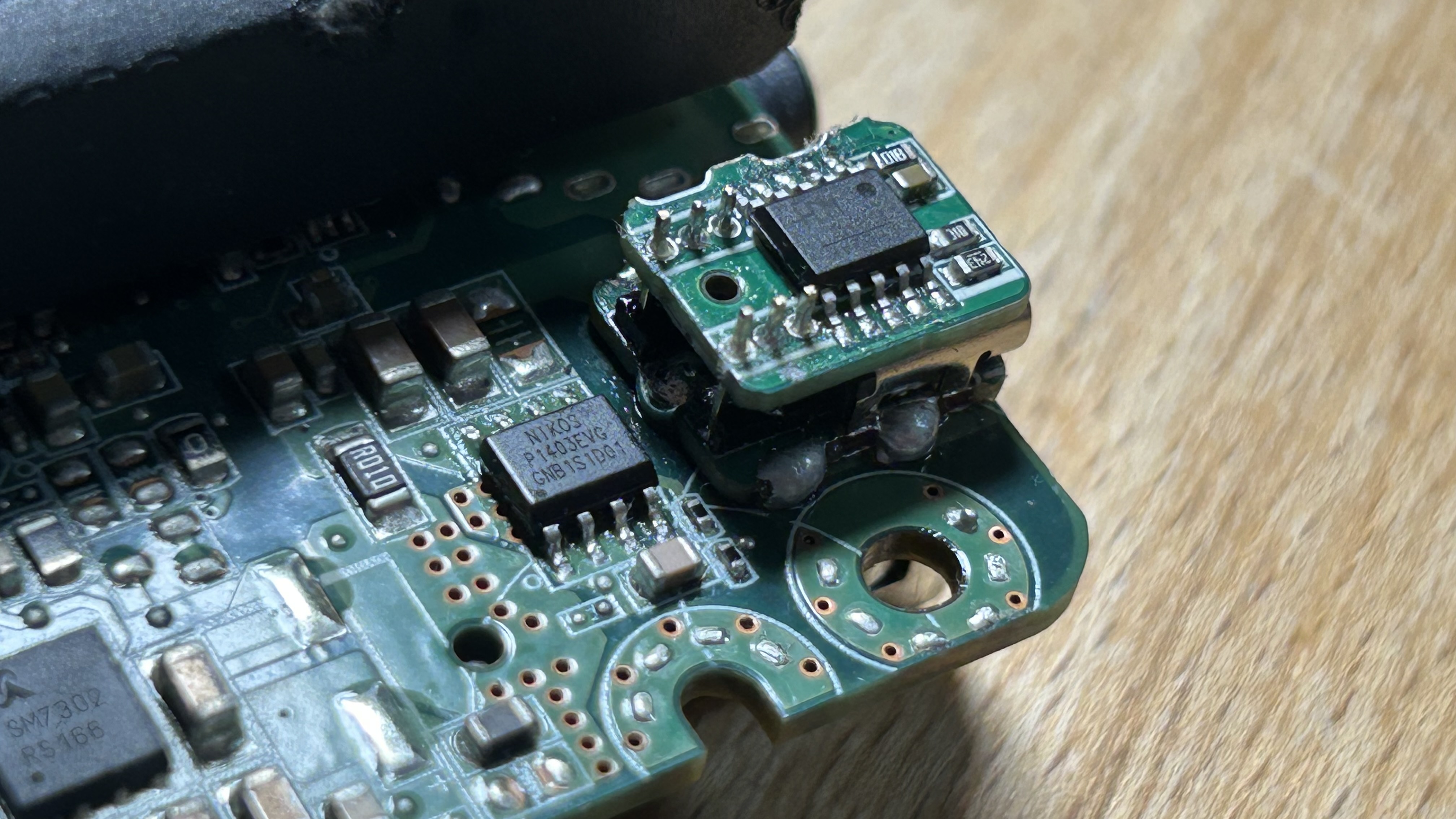
Stacked decoy DC power board
This project is based on the CH224K PD/QC decoy power module. It features non-destructive modification, small size, and compatibility with DC power sockets (as shown in Figure
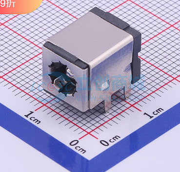
C381108). Similar packages can be used for
soldering. Note
that a stacking method is required, using a 1.27 1*3P connection. The soldering technique is important, and the bottom pads should be flattened as much as possible.
Note that
the board thickness should be 1mm; if it's too thick, it won't be able to be pried open. When prying it open, use another board to clamp it from the top and bottom. Adjust

the voltage selection
and the resistance value of resistor R1 in the white solder mask area as shown in the figure

. The finished product is shown in the figure.
PDF_DC Converter 2.zip
Altium_DC adapter 2.zip
PADS_DC converter 2.zip
BOM_DC to Typec PD_QC decoy.xlsx
91915
electronic
 1. Color silkscreen printing: Front copyright
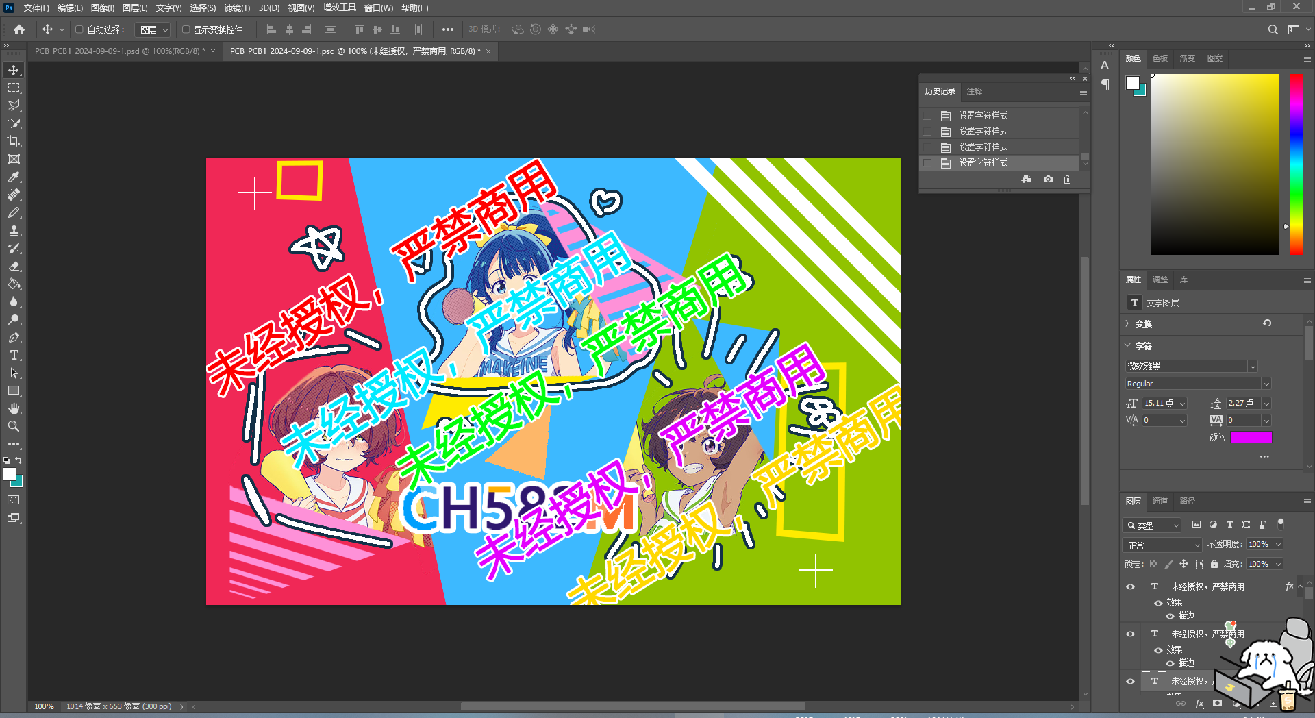


 京公网安备 11010802033920号

 Am29LV800BB-120DG5C1


