Acknowledgements:
Thanks to 00.01% and PhantomR for their open-source projects.
CV Keyboard, Three-Key Keyboard, Four-Key Keyboard, Nine-Key Keyboard, Wired Keyboard - JLCPCB EDA Open Source Hardware Platform (oshwhub.com)
【Three-Key Side-Light Backlit Keyboard】CH552G - JLCPCB EDA Open Source Hardware Platform (oshwhub.com)
This project references these two projects.
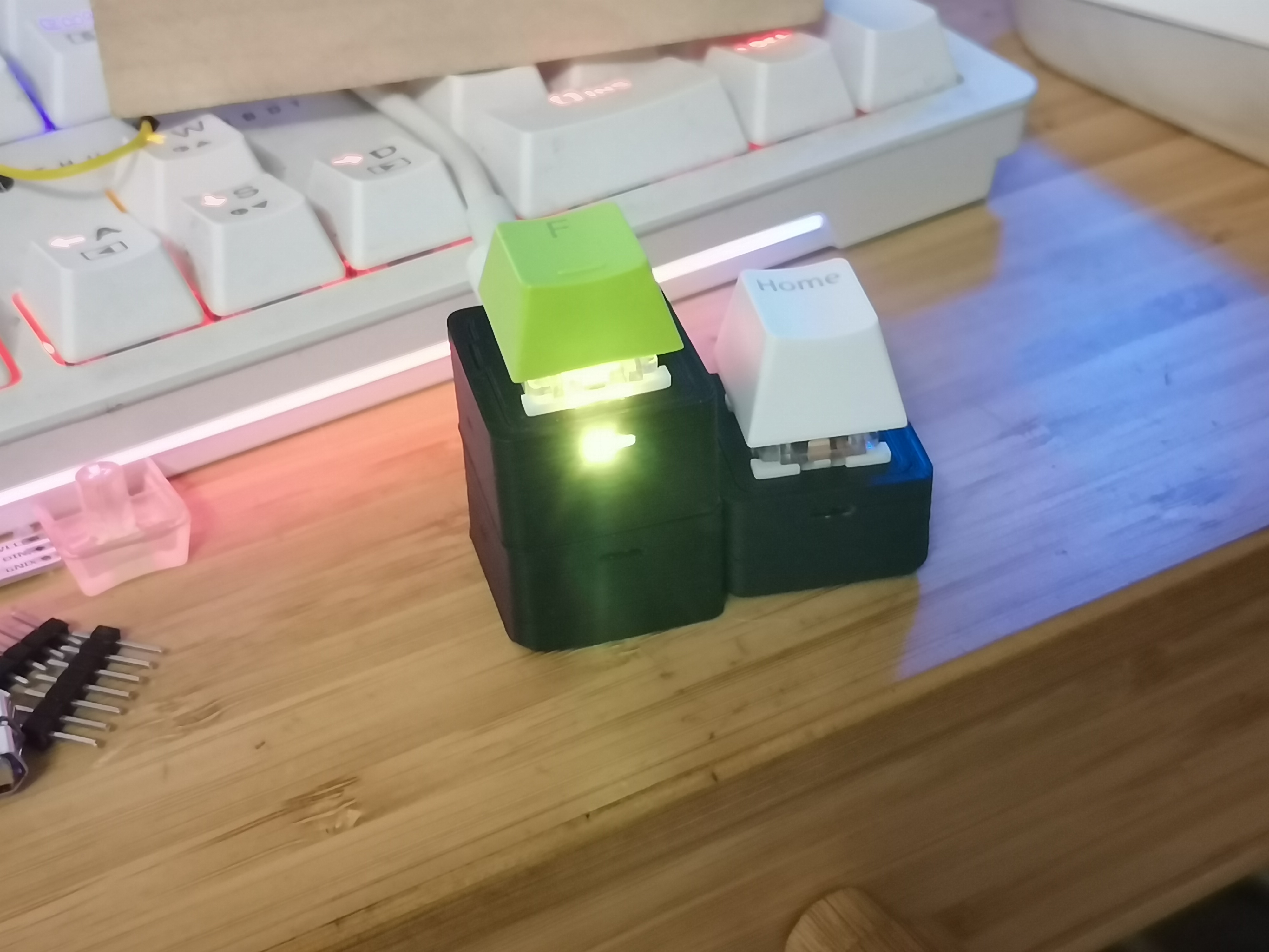
Main Text : This is a single-key keyboard based on the CH552, designed to minimize size limitations. It uses Kailh hot-swappable switches, includes a WS2812 LED, and a side button
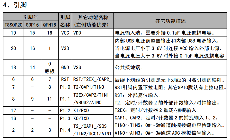
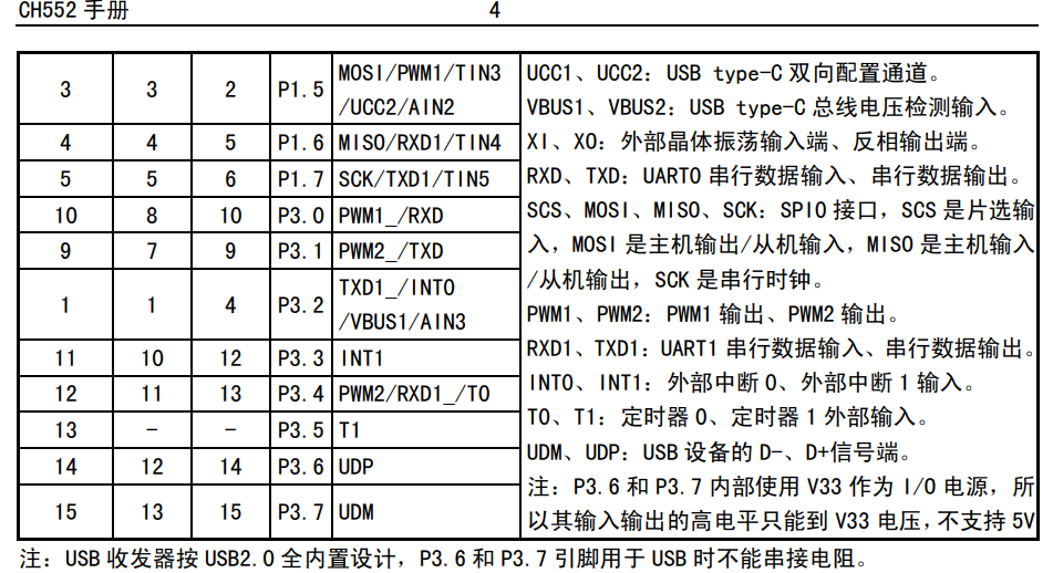
(which is not very useful) . September 28 Update: Good news: The V4 board with normal backlighting can now be used. Compared to the previous V2, the key lights are usable and compatible with previous cases. The drawback is the limited soldering space on the board, which may make operation more difficult. Image Display: #Left is V4, right is V2. V4 Replica Tips: 1. The LEDs below the keys need to have their pins manually folded under the keys, with the negative terminal facing the label after folding. 1. When attaching the key, try to keep it as close to the chip as possible to avoid difficulty in installing the key switch; 2. Before flashing, change the pins to P3.1 and P1.1, as shown in the picture below: In this way, the button will theoretically have the function of triggering an interrupt, but due to insufficient wiring space, the side button cannot currently be connected to pin 1 for interruption. Let someone else implement it. In addition, the LED light needs to modify the following code before compiling and flashing. Otherwise, it is no different from V2. 3. Although this version uses a lot of self-packaged parts, it has been verified to be problem-free, so you can place an order with confidence; 4. When exporting using the professional version, it may prompt that the through hole is outside the frame. That is the through hole of the LED in the V2 version. Just ignore it. Note: Do not use the V3 board. The LED pins of this version are incorrect and cannot be lit; If using V2, please use the unbound version. 24.7.17 Update Replica Tip 1: It is recommended to use the v2 board. Version 2 changes the reset button on the back to the flashing button (high bit of D+ pin). Flashing with v1 is very troublesome. 2. For complex lighting, it's recommended to change the two switch pins to 3.1 and 3.3 to utilize external INT interrupts. See attached diagrams or datasheets for other interrupt details. 3. Regarding the side buttons, the original design was based on 00.01% (link 1), but the casing design revealed that the size was too limited, making triggering impossible. It's currently in a semi-abandoned state. However, there's a version in the 3D model with side button openings (the kind of holes you poke with a pin or tweezers); this also provides the function of switching the lights on and off. 4. Due to current size limitations, the CH552 is mounted in the LED hole position on the switch mount (yes, the LED illuminates at the end of the button). If the switch mount doesn't support RGB, the chip pins should be moved to the existing C-port positioning post during design to avoid installation issues. 5. This project's PCB has a self-packaged library; it just has fewer unnecessary silkscreens for aesthetic reasons than others. All have been verified and are safe to use. 6. Before replicating, please review the projects of the two experts mentioned above; there may be important points I haven't covered. ( Attached image shows pin diagrams for interrupts: INT_NO_WDOG 0x006B 13, watchdog timer interrupt, low priority.)


 京公网安备 11010802033920号

 HDSP-210X


