Preface:
This design is for tinkering, learning, and technical exchange only.
No guarantees are made regarding the final result.
Production use is not recommended.
The author is not responsible for any losses incurred as a result
. It is not recommended to build this without a VNA, although this may not be necessary in practice.
Chip consistency may be poor, and your final result may differ. Routing
is a bit of a free-for-all; please be gentle with criticism. Open
Source License: CC BY-NC-SA 4.0 (NC = Non-Commercial).
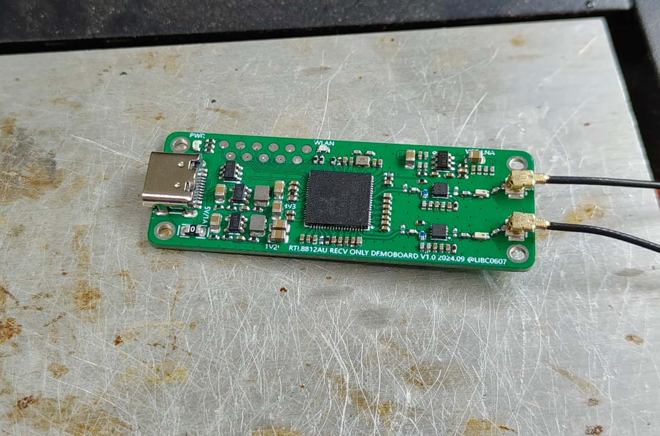
This is a
board drawn before CrabCast V1.0 to verify the schematic. It uses
an RTL8812AU main controller, QPL9503 LNA, bandpass filter, Type-C female port, and IPEX for antenna connection.
However, it works correctly with the schematic and verification, so this schematic is completely consistent with CrabCast. This does not contain 0201 components, making it relatively easy to solder. It's better
to keep it open source. Instructions:
PCB construction: Refer to the values marked in the schematic and board drawing.
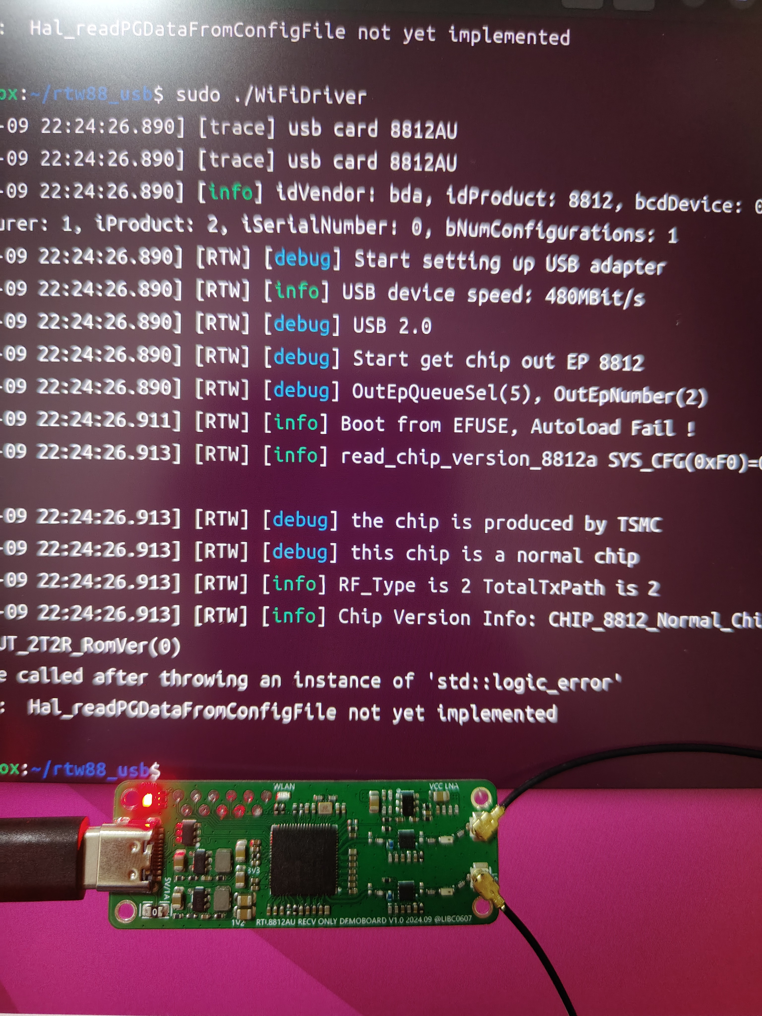
Chip purchase and driver: Completely consistent with CrabCast V1.0; refer to the instructions there.
PDF_8812AU Only accepts Demo V1.0.zip
Altium_8812AU only accepts Demo V1.0.zip
PADS_8812AU only accepts Demo V1.0.zip
BOM_8812AU only accepts Demo V1.0.xlsx
91990
Skystar Keyboard Development Expansion Board
It covers commonly used keyboard components, making it easy to learn keyboard-related programming and providing inspiration for DIY keyboards.
Project Introduction:
This project is primarily for learning software development for keyboard devices, covering commonly used keyboard components and serving as a reference for hardware design to some extent. Since it's for software development learning, you can choose your own development framework. I've chosen Rust, using the default framework from the official STM32F4 template.
Important!!!
I'm also a beginner, so many of my understandings may not be correct or accurate. Please forgive any errors or omissions.
Component Introduction:
Kailh hot-swappable switches
. Standard switches, compatible with most mechanical switches on the market. You can design your own package or use open-source packages designed by others on the LCSC community. Mainly divided into those with and without LED holes. Search for
"ws2812b 3528/6028 reverse-mount RGB LEDs"
for mechanical keyboards. There are various keyboard designs using
the 74HC165 shift register
, the most common being the matrix keyboard design. You can search for more information if you're interested. Here, I'm using a shift register solution, essentially expanding the GPIO to correspond one-to-one with the key switches. However, since it's not a true GPIO expansion, each pin needs a pull-up or pull-down resistor to ensure the level reverses when the switch is closed. For example, I connected a pull-up resistor, and grounded the other end of the key switch. This means the shift register returns high by default and low when pressed, thus determining if the key switch is pressed .
The AI32C touch chip is a 3-channel touch chip. The corresponding "pipe" on the PCB
isn't commonly found in finished mechanical keyboards, but it's present in many open-source mechanical keyboards, so I included it, and the output is connected to the shift register. Many finished keyboards now have rotary knobs, mainly using potentiometers and rotary encoders. A few open-source keyboards use motors (which are more expensive). Here, I've chosen the common EC11 rotary encoder. More and more keyboards are adding displays, although their practicality is low, they offer a lot of fun. Toggle switches are something that most keyboards have, and they are usually used to control the power supply or platform selection (Win and Mac) or the connection method selection (2.4, USB, BLE). The corresponding pins for the components are WS2812B 3528/6028 reverse-mounted RGB LED beads. DIN <=> C07 is a common GPIO pin for single-wire control. There is also a type that is controlled via SPI, which I haven't figured out yet. 74HC165 Shift Register Q7 <=> B04/SPI1_MISO Data Output Interface (wiring compatible with SPI control, but I'm using the normal control method and haven't yet looked into how SPI controls the shift register). PL# <=> B05 Load Pin CP <=> A05/SPI1_CLK Clock Pin CE# <=> D06 Enable Pin; in actual development, a pull-down resistor can be directly connected. D0 <=> K1 Button 1 D1 <=> K2 D2 <=> K3 D3 <=> K4 D4 <=> K5 D5 <=> K6 D6 <=> OUT1 Corresponds to the OUT1 output of the touch chip D7 <=> OUT2 Corresponds to the OUT2 output of the touch chip DS <=> _ In actual development, multiple shift registers will be used, connected together through this pin. AI32C Touch Chip KEY1 <=> 1 First segment of the three-segment filled area KEY2 <=> 2 KEY3 <=> 3 EC11 Rotary Encoder D <=> C12 EC11 push button switch A <=> C11 EC11 A pin B <=> C13 EC11 B pin 0.96-inch LCD full-color display SDA <=> C03/SPI2_MOSI SPI input SCL <=> B10/SPI2_CLK SPI clock RS/DC <=> D02 Data command selection RES <=> C08 Reset CS <=> B09/SPI2_CS Chip select LEDK <=> D03 Backlight toggle switch <=> C09 Software example ... indicates that other code is omitted. The complete code will be placed in the attachment at the bottom. Scanning buttons // The basic logic is to configure the corresponding GPIO and then read the data according to the requirements of the shift register let p = pac::Peripherals::take().unwrap(); ... let gpioa = p.GPIOA.split(); let gpiob = p.GPIOB.split(); let gpiod = p.GPIOD.split(); ... let q7 = gpiob.pb4.into_input(); let mut scan_cp = gpioa.pa5.into_push_pull_output(); let mut scan_pl = gpiob.pb5.into_push_pull_output_in_state(PinState::High); let mut scan_ce = gpiod.pd6.into_push_pull_output(); ... let mut scan_timer = p.TIM1.counter_us(&clocks); scan_timer.start(2.millis()).unwrap(); ... loop { if scan_timer.wait().is_ok() { scan_pl.set_low(); scan_pl.set_high(); let mut temp_data: [u8; 8] = [0; 8];
for i in 0..8 {
if q7.is_high() {
temp_data[i] = 1;
} else {
temp_data[i] = 0;
}
scan_cp.set_high();
scan_cp.set_low();
}
}
...
}
ws2812b (I mainly implemented a three-color cyclic breathing)
// This involved quite a few pitfalls, because the ws2812b is a single-pin communication, where the low level requires a delay of about ~200ns
// I naturally used the framework's delay_ns(200)
// However, it didn't work
// After trying and searching for a long time, I found that the delay_ns method couldn't achieve that precision
// Finally, referring to some C projects using an empty loop a specified number of times, there was also a small pitfall: you can't use cargo run
// You need to use cargo run --release, otherwise the time will still exceed the limit and cause it to have no effect
// The logic of the breathing light is to convert the RGB value to a format such as HSV, then adjust the brightness and convert it back to RGB format .
// I didn't implement the conversion logic myself, I directly used a third-party library to handle it
...
pub fn set_color(
pin: &mut LedPin,
delay: &mut Delay,
rgb_color: (u8, u8, u8),
) -> Result<(), u32>
where
Delay: DelayNs,
LedPin: OutputPin,
{
let grb_color = [rgb_color.1, rgb_color.0, rgb_color.2];
for c in grb_color {
for i in 0..8 {
let mask = 0x80 >> i;
if c & mask != 0 {
pin_high(pin)?;
delay.delay_us(1);
pin_low(pin)?;
delay_250ns();
} else {
pin_high(pin)?;
delay_250ns();
pin_low(pin)?;
delay.delay_us(1);
}
}
}
Ok(())
}
...
// Part of the breathing light code
let current_color = self.colors[self.current_color_index as usize];
let current_color_u8: Srgb = current_color
.darken(self.dark_percent as f32 / 100.0)
.into_format();
Considering the length, I won't paste all the code here (my code is also average, if needed, please download the complete code in the attachment and check it yourself). The rest mainly discusses the idea of
the touch part
// First, polling every 2 milliseconds, then determining if there is a previous touch, if not, recording the current touch key
// If there is a record, then determining the sliding direction based on the current value
// My implementation requires Key1 and Key3 to slide to each other's positions, Key2 supports single click.
EC11 rotary encoder
// There are many documents on rotary encoder control itself, so I won't go into detail
// I mainly want to talk about the pitfalls I encountered when using rotary encoder to control volume
// If it is only used as an HID Sending VolumeUp or VolumeDown to the KeyBoard device has no effect (maybe there's some other setting I don't know about).
// The solution is to add another Consumer device.
Finally
, I don't know what else to say. Happy National Day in advance!
Tkx Demo.mp4
source_code.zip
PDF_SkyStar Keyboard Development Extension Board.zip
Altium_SkyStar Keyboard Development Extension Board.zip
PADS_SkyStar Keyboard Development Expansion Board.zip
BOM_SkyStar Keyboard Development Expansion Board.xlsx
91993
FPC - Pressure and Temperature Acquisition Insole
The FPC integrates the insole circuitry of pressure and temperature sensors, which is led out via an FPC ribbon cable.
Project Overview:
This project focuses on the data acquisition circuitry of a foot monitoring insole based on the ESP32S3 microcontroller, capable of detecting pressure and temperature. The pressure sensor used is an IMS-C10A, and the temperature sensor is an NTC8250. After connecting subsequent peripheral circuitry, pressure and temperature can be determined by changes in resistance.
PDF_fpc-Pressure and Temperature Acquisition Insole.zip
Altium_fpc-Pressure and Temperature Acquisition Insole.zip
PADS_fpc-Pressure and Temperature Acquisition Insole.zip
BOM_fpc-Pressure and Temperature Acquisition Insole.xlsx
91994
DEMO+HI2821
The BearPi-Pico H2821 Star Flash Development Board achieved a distance of 3.3 kilometers in distance testing. This project is a secondary development based on the "BearPi-Pico H2821 Star Flash Development Board". The main purpose is to make the BearPi development board similar to a walkie-talkie for voice transmission in order to verify the distance.
Project Introduction:
This project involves secondary development based on the "BearPi-Pico H2821 Star Flash Development Board". Having previously worked on wireless products, primarily Bluetooth 2.4G, I've always been interested in related news.
I've also been following Huawei's Star Flash development board, but haven't seen much information about it. In August, I saw BearPi had the Star Flash development board and immediately bought two. After receiving them, I performed some simple tests according to the engineering instructions (I didn't know the difficult ones), and everything went smoothly.
In September, I saw that BearPi had conducted distance tests on the development board, achieving an astonishing 3.3 kilometers! I can only say it's amazing. Previously, using Qualcomm's CC2529+CC8520, the distance was only about 150 meters in good environments, and only about 60 meters in complex environments.
This stark contrast made me wonder if I could also make the BearPi development board into a walkie-talkie mode to test the distance. If the distance is far enough, I believe Star Flash will definitely see better development, and I believe it will provide more and better choices for domestic chip substitution.
The BearPi-Pico H2821 is a core board based on a highly integrated 2.4GHz SoC BLE&SLE as the main control chip. It features flexible digital interfaces, with I/O ports that can be reused for any function. It integrates a high-performance 32-bit microprocessor (MCU), a hardware security engine, and rich peripheral interfaces, including SPI, UART, I2C, PWM, GPIO, USB 2.0, NFC Tag, PDM, I2S/PCM, QDEC, and a KEYSCAN keyboard scanning circuit. It supports 8-channel 13-bit resolution ADCs, and the ADCs can be connected to an audio AMIC. It has built-in SRAM and encapsulated Flash memory, and supports running programs on the Flash memory.
BearPi-Pico H2821 official website: https://bearpi.cn/core_board/bearpi/pico/h2821/
More reviews of BearPi-Pico H2821 can be found here: https://bbs.eeworld.com.cn/thread-1290106-1-1.html#pid3352022
Project Functionality :
The main functional settings are as follows:
1. Add a PCB board to house the components and the BearPi development board.
2. Add a battery and corresponding circuitry to the development board, as it can only be powered by USB. I mainly use it for distance testing, hence the need for a battery.
3. Add two digital microphone inputs and one I2S output for recording and listening to sound, as well as volume adjustment and amplification functions, especially outdoors where sound can be noisy.
Project Parameters
: Specifically, it has two microphone inputs and one audio output. The two boards are identical, similar to a walkie-talkie.
Principle Analysis (Hardware Description)
: The hardware was basically unchanged; I mainly borrowed the BearPi development board, adding a microphone input, I2S output, power-on circuit, and charging circuit.
Software code:
Software is completely foreign to me, but it's a piece of cake for the BearPi experts. I consulted the BearPi assistant, and they'll write a PR to solicit interest in this project—basically, no problem, what can it do? Haha.
So I started making the PCB and purchasing components for surface mount assembly.
After several days of purchasing and mounting, it's finally finished tonight. Currently, only the hardware is working; the voltage and other settings are OK. I'll debug it after the software is finished, and then we can test it. I'll record the process from time to time below. Thank you everyone.
1ae884f54f3b73582afd5bb5c106b3b.jpg
144b02f0e05eee10002c7dfa9077574.jpg
3a06bb02b8c617ecf6d378b3e5b280f5.mp4
PDF_DEMO+HI2821.zip
Altium_DEMO+HI2821.zip
PADS_DEMO+HI2821.zip
BOM_DEMO+HI2821.xlsx
91996
Modular car
Basic version, with pre-drilled mounting holes; additional features can be added later as needed.
Basic functions:
1. Four-channel N20 motor drive;
2. LED lighting system;
3. Tri-color LED indicator;
4. Ultrasonic obstacle avoidance module;
5. Bluetooth communication module;
8cc59cd62d66818eb0c1c7582d44b76f.mp4
PDF_Module Car.zip
Altium_Module Car.zip
PADS_Module Car.zip
BOM_Module Car.xlsx
91997
Smart RCL meter
An RCL meter is an electronic test device used to measure resistance, capacitance, and inductance (RCL stands for Resistance, Capacitance, and Inductance). It is commonly used in electronic engineering and electrical testing to measure and analyze the electrical characteristics of electronic components. An RCL meter can provide accurate measurements of resistance, capacitance, and inductance values.
Project Overview
This project is a simple RCL (
Resistance, Capacitance, and Inductance) meter. An RCL meter is an electronic test device used to measure resistance, capacitance, and inductance (RCL stands for Resistance, Capacitance, and Inductance). It is commonly used in electronic engineering and electrical testing to measure and analyze the electrical characteristics of electronic components. An RCL meter provides accurate measurements of resistance, capacitance, and inductance values, which is crucial for researching and developing new electronic devices, maintaining existing electronic systems, and troubleshooting.
Project Functions
The measurement functions of an RCL meter include, but are not limited to, voltage measurement, frequency measurement, open-circuit voltage correction, short-circuit voltage correction, resistance measurement, and capacitance/inductance measurement. These functions make the RCL meter an indispensable tool for electronic engineers and electrical technicians. By using an RCL meter, detailed information about the resistive, capacitive, and inductive components in a circuit can be obtained, which is essential for optimizing circuit design, improving equipment performance, and ensuring safe operation of equipment.
Furthermore, the use of an RCL meter involves several safety and maintenance considerations, such as proper grounding methods, the use of voltage and fuses, and proper placement of the instrument to avoid radio frequency interference. These safety measures aim to ensure the accuracy and safety of the testing process and prevent potential electrical hazards during testing.
In summary, the RCL meter is a versatile electronic test instrument that helps engineers and technicians better understand and optimize the performance of electronic systems by providing accurate resistance, capacitance, and inductance measurements. Meanwhile, the safety guidelines that must be followed when using an RCL meter ensure the reliability of the testing process and the safety of the operators.
Project parameters
: This section can be used to describe the relevant functional parameters of the project. Example:
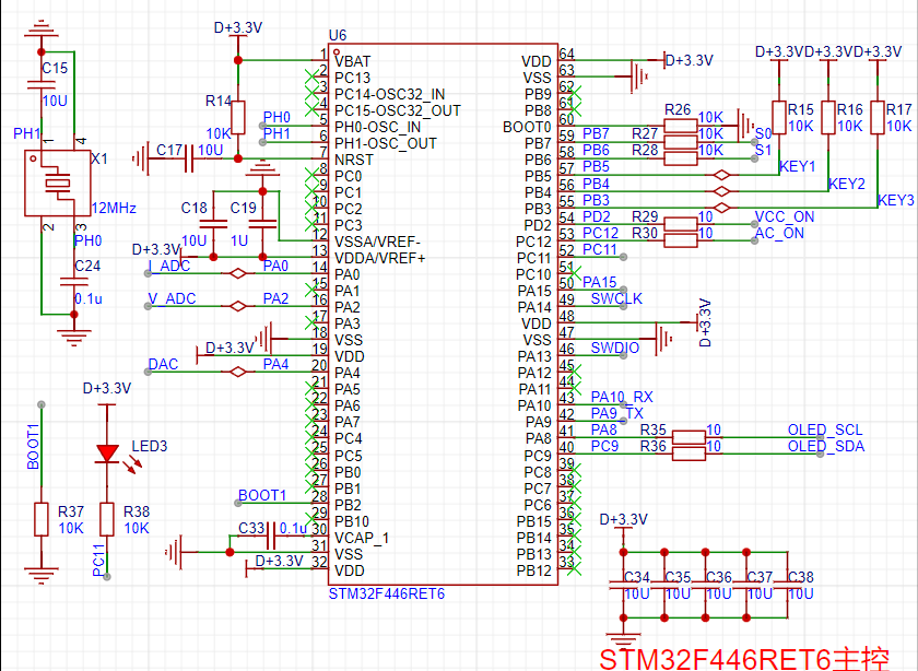
This design uses an STM32F446RET6 main controller.
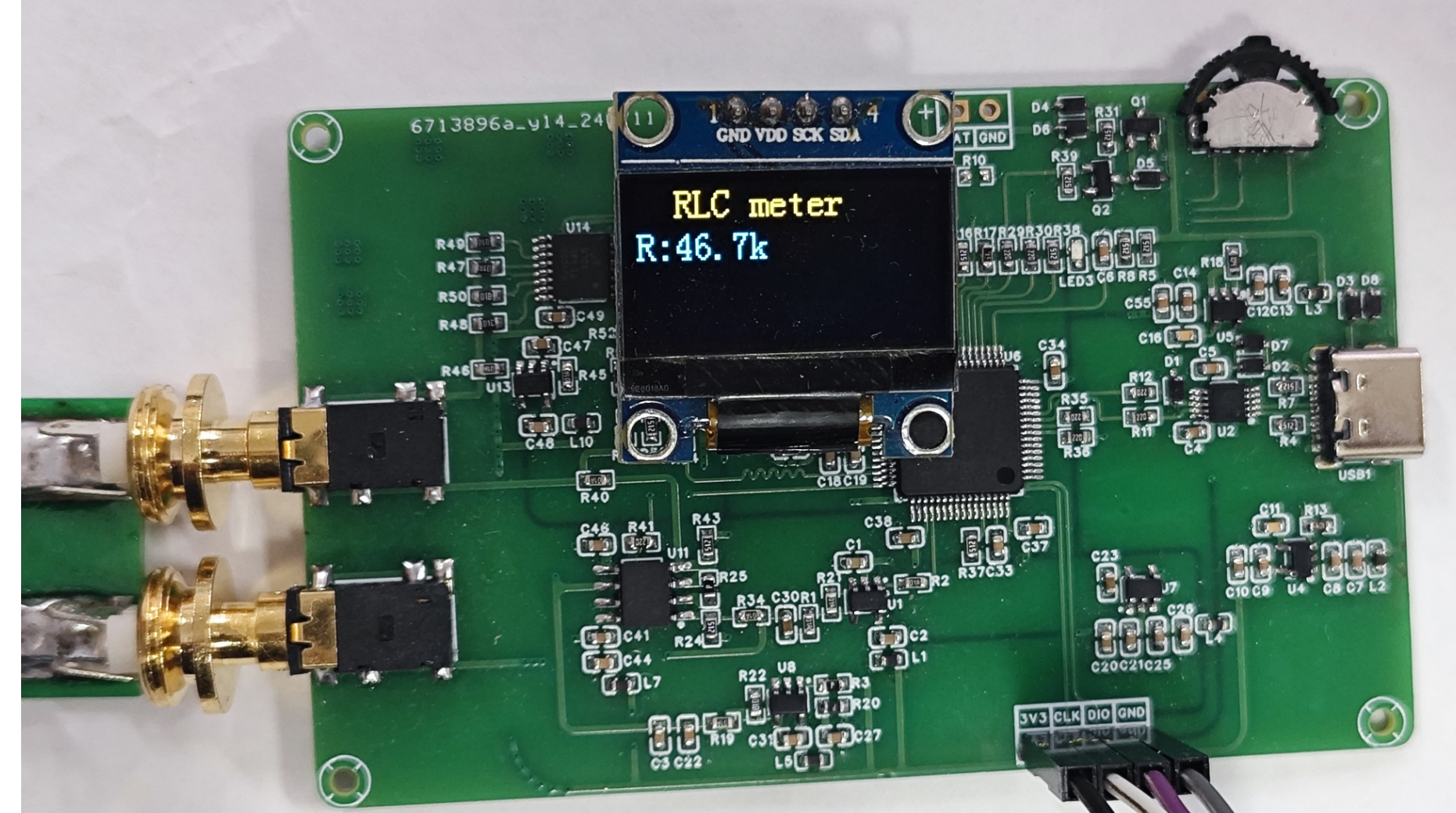
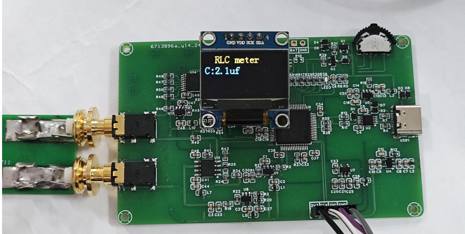
This design uses an OLED display; the top row displays the currently tested L, C, and R values.
This project has an automatic range switching function and a wide measurement range, which can meet general needs.
Note: Do not test high-voltage components that have not undergone proper discharge treatment, as this may easily damage the circuit.
原理解析(硬件说明)
此处可填写项目的设计原理,将设计的原理拆分解析,示例:
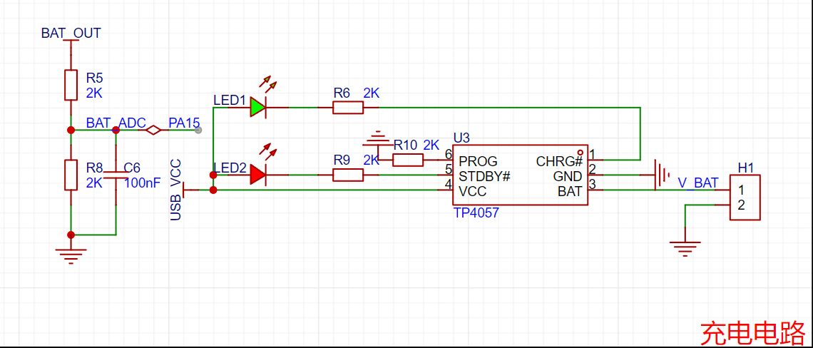
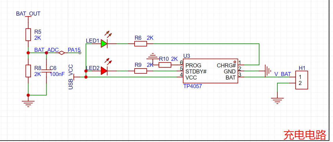
本项目由以下部分组成,主控部分、正负电源部分、充电电路部分、测试电路部分组成,本项目主要是通过主控发出DAC,再给到一级运放提供偏执电压,再经过二级运放,对采到的电流,电压信号进行采集,放大的处理,最后再将采集到的信号送到单片机的DAC,单片机进行计算,得出R,C,L的值。


1--主控电路:

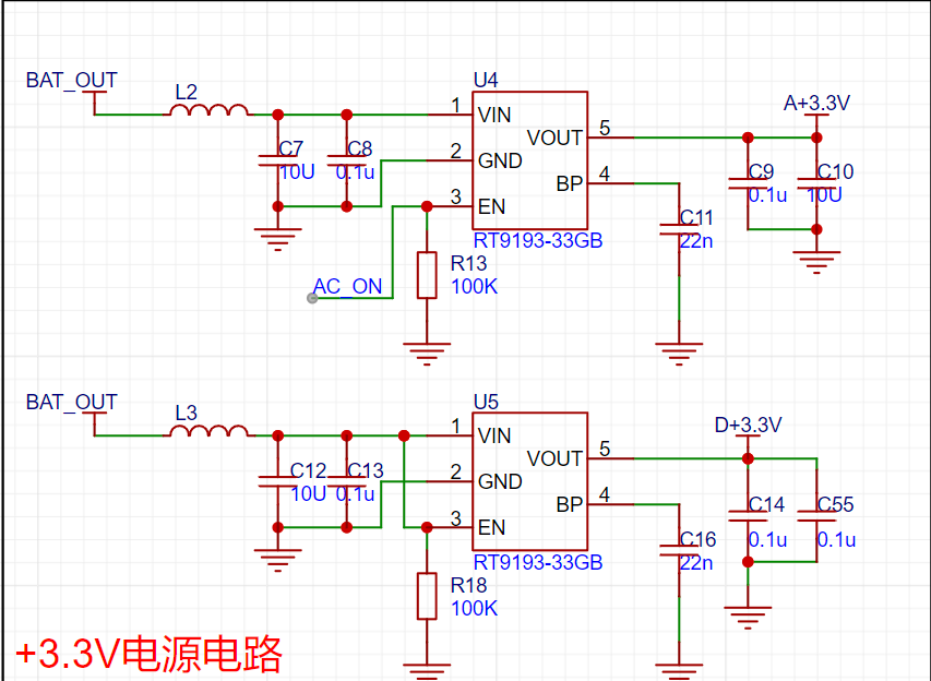
2--正负电源电路:

3--充电电路:
4--测试电路:


软件代码
// 测电阻自动换挡
void R_GEARS_APP(void)
{
uint8_t x, y, z;
float global_min_value = FLT_MAX;
float difference_value[4][4][4]; // VPP1-VPP2 差值的绝对值
struct ADC_DATA AUTO_ADC1_DATA[4][4]; // 自动换挡数据
struct ADC_DATA AUTO_ADC2_DATA[4][4]; // 自动换挡数据
struct GEARS_MIN gears_min[4]; // 每一挡位最小数值的数据
// 得到所有档位的值将所得到的值统计出来
for (x = 0; x < 4; x++) // 档位
{
for (y = 0; y < 4; y++) // 放大倍数档位
{
//
IR_gears_set(x); // Gear shift value for sampling resistor shifting
LCR_gears_set(y); // Amplification factor shifting
osDelay(10); // Wait for voltage stabilization after shifting gears
ADC_DATA_APP(); // Acquire VPP for each unit
// Save gear value
AUTO_ADC1_DATA[x][y].gears.gears_IR = x;
AUTO_ADC2_DATA[x][y].gears.gears_IR = x;
// Save sampling resistor value
AUTO_ADC1_DATA[x][y].gears.gears_IR_data = GREAS_DATA.gears.gears_IR_data;
AUTO_ADC2_DATA[x][y].gears.gears_IR_data = GREAS_DATA.gears.gears_IR_data;
// Save the magnification level value:
AUTO_ADC1_DATA[x][y].gears.gears_LCR = y;
AUTO_ADC2_DATA[x][y].gears.gears_LCR = y;
// Save the magnification value:
AUTO_ADC1_DATA[x][y].gears.gears_LCR_data = GREAS_DATA.gears.gears_LCR_data;
AUTO_ADC2_DATA[x][y].gears.gears_LCR_data = GREAS_DATA.gears.gears_LCR_data;
// Save the peak-to-peak value
: AUTO_ADC1_DATA[x][y].ADC_VPP = ADC1_DATA.ADC_VPP;
AUTO_ADC2_DATA[x][y].ADC_VPP = ADC2_DATA.ADC_VPP;
}
}
// Find the minimum difference in VPP at each level:
for (x = 0; x < 4; x++)
{
gears_min[x].Value_MIN = FLT_MAX;
for (y = 0; y < 4; y++)
{
for (z = 0; z < 4; z++)
{
difference_value[x][y][z] = fabs(AUTO_ADC1_DATA[x][y].ADC_VPP - AUTO_ADC2_DATA[x][z].ADC_VPP); // Get the absolute value of the VPP difference floating-point number
if (difference_value[x][y][z] < gears_min[x].Value_MIN) // Minimum value under all combinations of X and Y
{
gears_min[x].Value_MIN = difference_value[x][y][z];
// Record the minimum amplification level
gears_min[x].ADC1Index_MIN = y;
gears_min[x].ADC2Index_MIN = z;
// Record the sampling resistor value of the minimum group
gears_min[x].ADC1gears_IR = AUTO_ADC1_DATA[x][y].gears.ge
void ADC_DATA_APP(void)
{
// Convert voltage values
for (int i = 0; i < ADC_LEN; i++)
{
ADC1_V[i] = ADC1_BUUF[i] * 3.3f / 4096.0f;
ADC2_V[i] = ADC2_BUUF[i] * 3.3f / 4096.0f;
}
// Perform low-pass filtering on the ADC voltage data, with a cutoff frequency of 1kHz
arm_fir_f32_ADC1();
arm_fir_f32_ADC2();
// When performing low-pass filtering, the initial waveform has boundary effects, and the calculated minimum value is incorrect.
// The method to eliminate boundary effects here is not to start the calculation from the very beginning, but to shift the calculated data backward and skip the incorrect data.
// Boundary effects affect the first x samples. The specific number of samples can be checked by referring to the waveform. Just skip the boundary effect region.
const uint32_t ADC1_boundary_effect_samples = 200;
const uint32_t ADC2_boundary_effect_samples = 200;
// 调整数组指针和长度跳过边界效应区域
float32_t *start_ADC1_ptr = ADC1_V_Output + ADC1_boundary_effect_samples;
float32_t *start_ADC2_ptr = ADC2_V_Output + ADC2_boundary_effect_samples;
uint32_t ADC1_adjusted_len = ADC_LEN - ADC1_boundary_effect_samples;
uint32_t ADC2_adjusted_len = ADC_LEN - ADC2_boundary_effect_samples;
// 最小值
arm_min_f32(start_ADC1_ptr, ADC1_adjusted_len, &ADC1_DATA.ADC_MIN, &ADC1_DATA.Index_MIN);
arm_min_f32(start_ADC2_ptr, ADC2_adjusted_len, &ADC2_DATA.ADC_MIN, &ADC2_DATA.Index_MIN);
// Adjust the index to reflect the index of the original array
ADC1_DATA.Index_MIN += ADC1_boundary_effect_samples;
ADC2_DATA.Index_MIN += ADC2_boundary_effect_samples;
// Maximum value
arm_max_f32(ADC1_V_Output, ADC_LEN, &ADC1_DATA.ADC_MAX, &ADC1_DATA.Index_MAX);
arm_max_f32(ADC2_V_Output, ADC_LEN, &ADC2_DATA.ADC_MAX, &ADC2_DATA.Index_MAX);
// Peak value
ADC1_DATA.ADC_VPP = (ADC1_DATA.ADC_MAX) - (ADC1_DATA.ADC_MIN);
ADC2_DATA.ADC_VPP = (ADC2_DATA.ADC_MAX) - (ADC2_DATA.ADC_MIN);
}
// Low-pass filter coefficients 64th order filter Sampling frequency: 134635HZ Cutoff frequency: 1Khz Requires precision but cannot be too high The higher the filter order, the more accurate the filtering, but the slower the filtering speed
const float firCoeffs32LP[NUM_TAPS] =
{
0.001636382425, 0.001727766707, 0.001915873145, 0.002206306905, 0.002603286877,
0.003109541256, 0.003726221155, 0.004452842288, 0.005287249107, 0.006225605495,
0.007262411993, 0.008390551433, 0.00960135553, 0.01088470593, 0.01222915016,
0.01362204459, 0.01504972111, 0.01649766229, 0.01795070246, 0.01939323545,
0.02080943249, 0.0221834667, 0.02349973656, 0.02474309318, 0.02589905635,
0.02695403248, 0.02789550647, 0.02871222794, 0.02939438447, 0.02993373573,
0.03032374196, 0.03055966087, 0.03063862212, 0.03055966087, 0.03032374196,
0.02993373573, 0.02939438447, 0.02871222794, 0.02789550647, 0.02695403248,
0.02589905635, 0.02474309318, 0.02349973656, 0.0221834667, 0.02080943249,
0.01939323545, 0.01795070246, 0.01649766229, 0.01504972111, 0.01362204459,
0.01222915016, 0.01088470593, 0.00960135553, 0.008390551433, 0.007262411993,
0.006225605495, 0.005287249107, 0.004452842288, 0.003726221155, 0.003109541256,
0.002603286877, 0.002206306905, 0.001915873145, 0.001727766707, 0.001636382425};
/**********************************************************************************************************
* 函数名: arm_fir_f32_ADCx
* 功能说明: 调用函数arm_fir_f32_lp实现低通滤波器
* 形参:无
* 返回值: 无
**********************************************************************************************************/
static void arm_fir_f32_ADC1(void)
{
uint32_t i;
arm_fir_instance_f32 S;
float *inputF32, *outputF32;
// 初始化输入输出缓存指针
inputF32 = &ADC1_V[0];
outputF32 = &ADC1_V_Output[0];
// 初始化结构体S
arm_fir_init_f32(&S, NUM_TAPS, (float32_t *)&firCoeffs32LP[0], &firStateF32[0], blockSize);
// 实现FIR滤波,这里每次处理1个点
for (i = 0; i < numBlocks; i++)
{
arm_fir_f32(&S, inputF32 + (i * blockSize), outputF32 + (i * blockSize), blockSize);
} The complete assembly diagram can be placed here.
Figure 1: Resistance test diagram Figure 2: Capacitance test diagram Figure 3: Inductance test diagram


PDF_SmartRCLTable.zip
Altium_SmartRCLTable.zip
PADS_Smart RCL Table.zip
BOM_Smart RCL Table.xlsx
91998
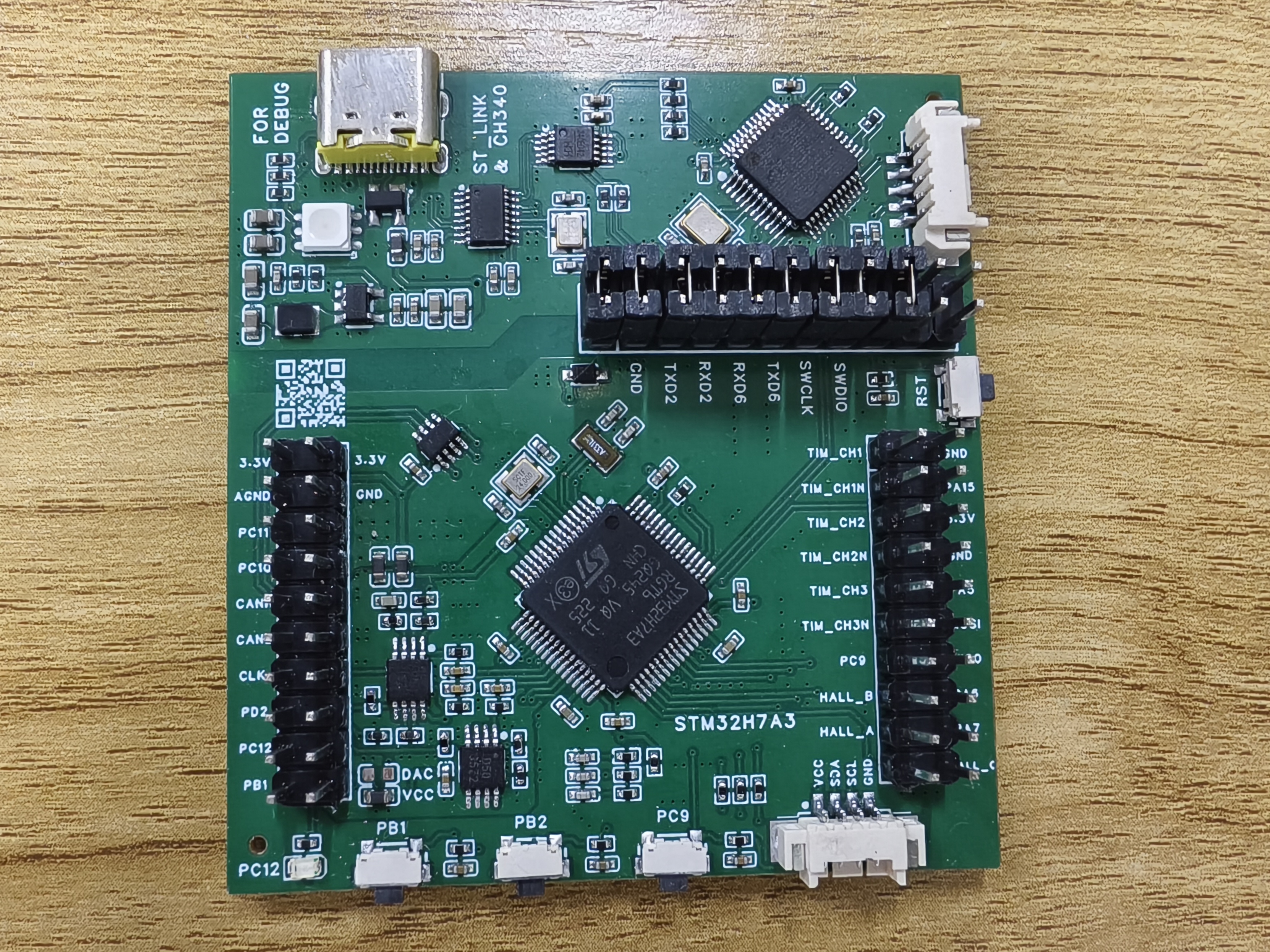
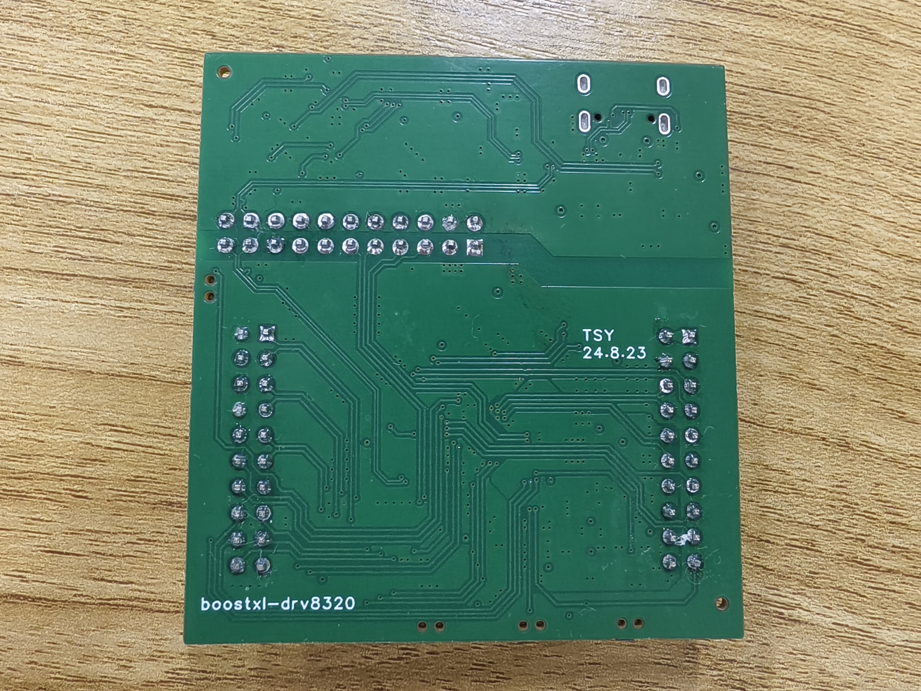
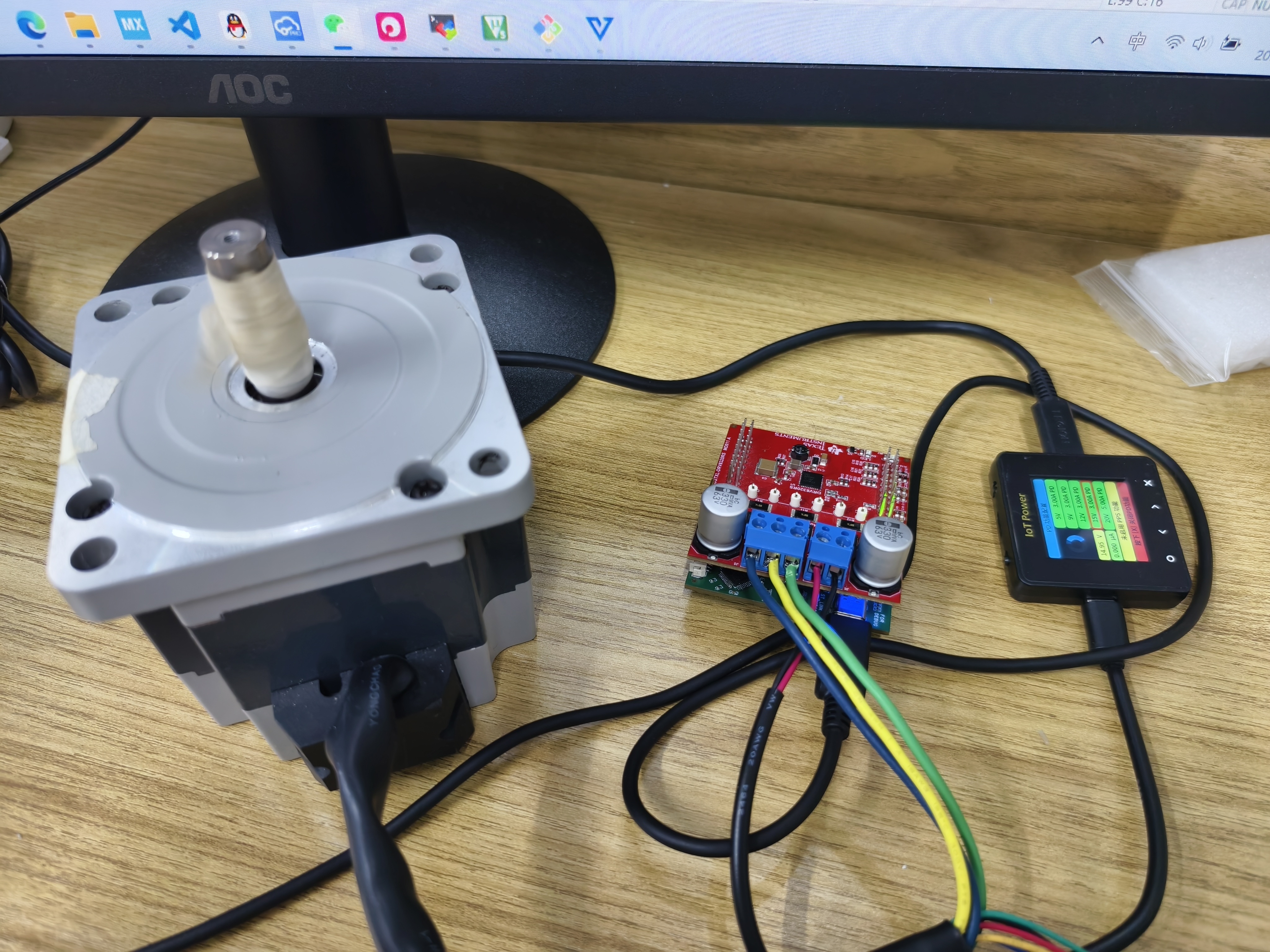
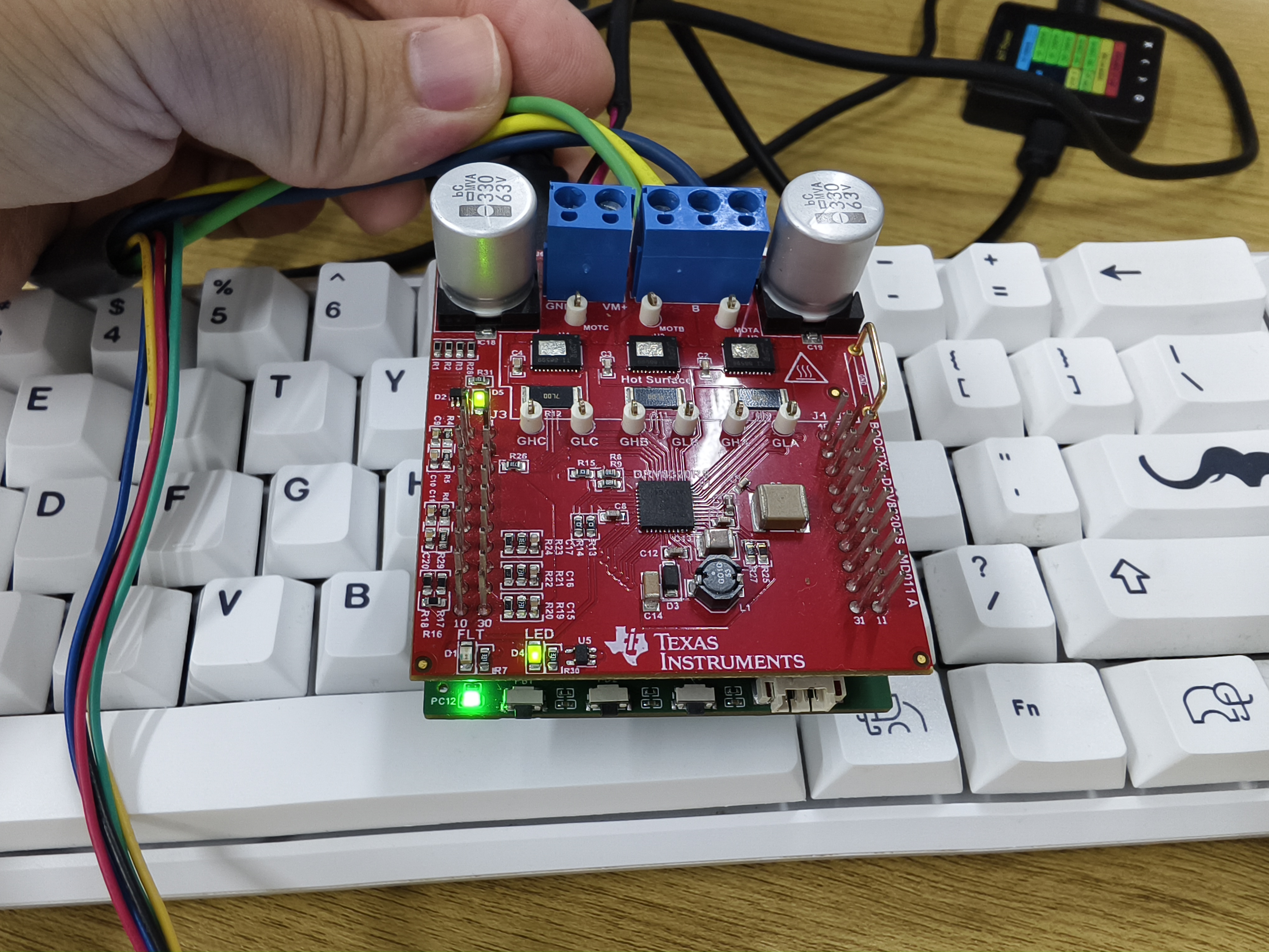
STM32H7A3-FOC Motor Development Board - LaunchPad
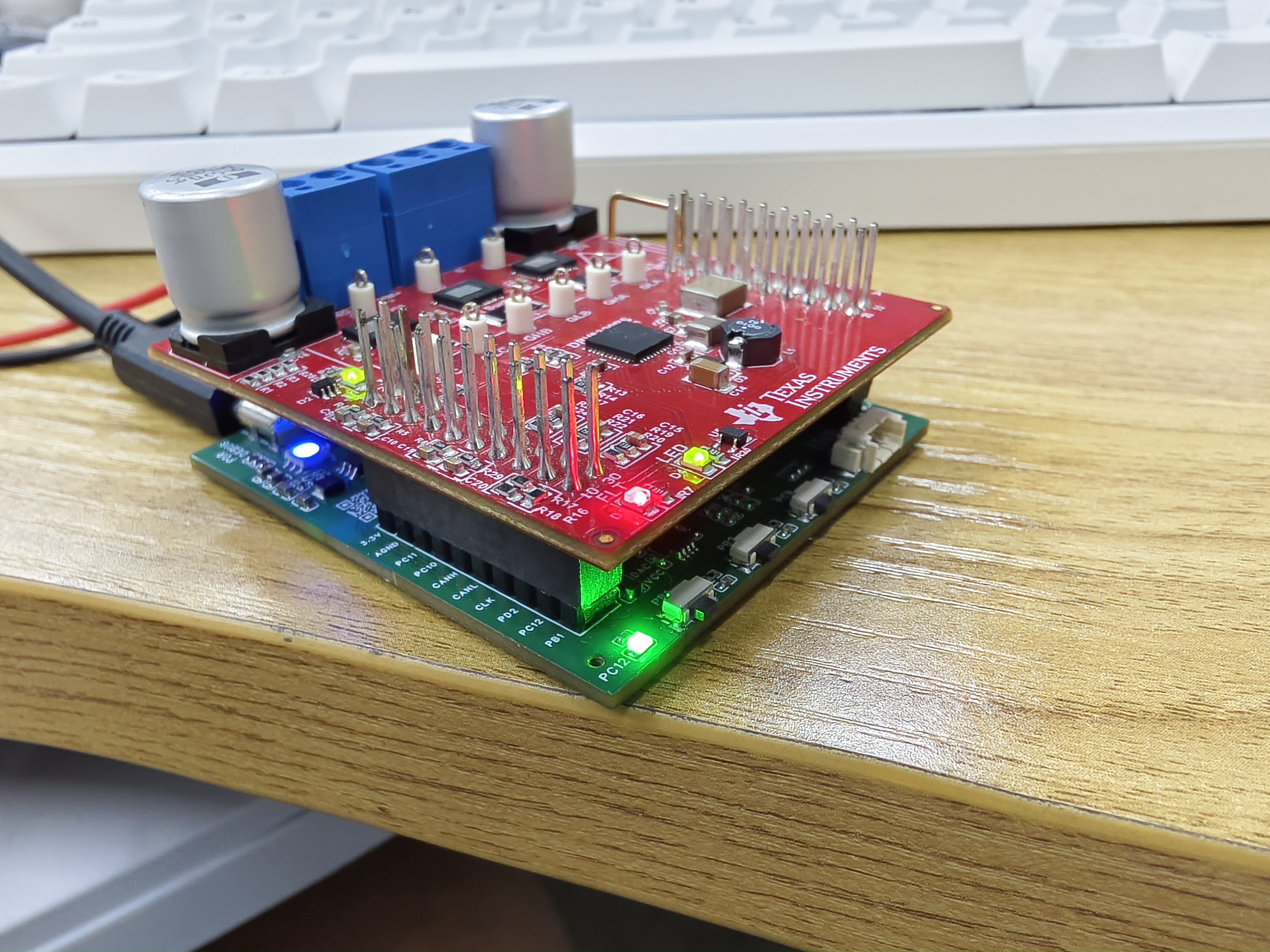
This development board was designed to be compatible with TI's BOOSTXL-DRV8320RS motor drive module, mimicking the appearance of TI's MSP430 series boards.
This development board, designed to be compatible with TI's BOOSTXL-DRV8320RS motor driver module, mimics the appearance of TI's MSP430 series boards.
The board uses the STM32H7A3RGT6 as the main control chip, with an ARM Cortex M7 core and a 280MHz clock speed. The M7 core is chosen for its double-precision floating-point operation and ability to execute two instructions per cycle, allowing for the execution of complex algorithms.
This design employs an all-in-one debugging method, requiring only a single USB Type-C interface for debugging. A USB hub chip expands the interface to provide three ports: one for the onboard CH340, one for the onboard ST-LINK, and one for the MCU's USB device. The onboard ST-LINK can switch firmware to JLINK-OB and also features a virtual serial port. The ST-LINK virtual serial port connects to UART6 for the RT-Thread console; the CH340 connects to UART2 for the VOFA+ host computer.
The operational amplifier circuit in the schematic is only half complete, forming a non-inverting proportional amplifier circuit with the upper-layer BOOSTXL-DRV8320RS board. Users can modify it according to their needs. Motor current and voltage sampling tests showed normal operation, and a non-inductive current loop can be closed.
ST-LINK circuit reference project: STLINK/JLINK_OB/DAPLINK - LCSC Open Source Hardware Platform (oshwhub.com)


PDF_STM32H7A3-FOC Motor Development Board-LaunchPad.zip
Altium_STM32H7A3-FOC Motor Development Board-LaunchPad.zip
PADS_STM32H7A3-FOC Motor Development Board-LaunchPad.zip
BOM_STM32H7A3-FOC Motor Development Board-LaunchPad.xlsx
91999
electronic


 京公网安备 11010802033920号

 ISL35822IK


