The known problem is that the duty cycle is erratic, but it stops when the power is plugged in. I've tried the process of elimination; the erratic cycling started as soon as I soldered the 2.2kΩ voltage divider resistor to the voltage sensor. I don't know why. I'd appreciate any help from experts. Currently, the motor can turn but vibrates and makes a lot of noise.
PDF_vesc Simulated Electric Vehicle Controller - Semi-verified.zip
Altium_vesc Simulated Electric Vehicle Controller - Semi-verified.zip
PADS_vesc Simulated Electric Vehicle Controller - Semi-verified.zip
BOM_vesc Simulated Electric Vehicle Controller - Semi-Verification.xlsx
92013
(ELEC3300 Course Project) Solar Panel Maximum Power Point Tracking Main Control Board
Maximum power point tracking control board for solar panels (perturbation-observation method), using STM32F103VET6 as the controller, HKUST Spring 2024 ELEC3300 course design.
This design supports:
1. Real-time monitoring of solar panel voltage and current, and tracking of the maximum power point to maximize power generation efficiency.
2. Dual PWM output interfaces, supporting horizontal and tilt motors for sun tracking (similar to sunflowers) (requires a photoresistor to determine the sun's position).
3. One 34-pin DuPont header/female header for FSMC-simulated 8080 timing screen control (https://item.taobao.com/item.htm?_u=63uuotm01aae&id=680271103710&spm=a1z09.2.0.0.67002e8dHxmsrW&skuId=5045244538637).
4. Reserved SD card interface for log storage (untested).
5. Reserved SPI and CAN interfaces
. 6. I2C for connecting to an MPU6050 gyroscope or OLED screen.
7. USB automatic download circuit (untested).
8. A demo video showcasing a multi-solar node monitoring system using a USART serial port connected to an ESP32 microcontroller
: [HKUST 2024 Spring ELEC3300 Course Project Demo] https://www.bilibili.com/video/BV1rqsheLErt/?share_source=copy_web&vd_source=1909179bdb0bedd7f9d162ef025d08b7
Software open-source address: https://github.com/OW1TY2/ELEC3300-2024-Spring-MPPT
PDF_(ELEC3300 Course Project) Solar Panel Maximum Power Point Tracking Control Board.zip
Altium (ELEC3300 course project) Solar panel maximum power point tracking control board.zip
PADS (ELEC3300 Course Project) Solar Panel Maximum Power Point Tracking Control Board.zip
BOM_(ELEC3300 Course Project) Solar Panel Maximum Power Point Tracking Main Control Board.xlsx
92014
CH571-based keyboard
Bluetooth keyboard board made by ch571
This keyboard, based on the CH571 chip, features Bluetooth and USB functionality. It has six keys, each with a WS2812 full-color LED underneath. It also includes two encoders for easy configuration and can even be used as a mouse. It has charging and Bluetooth indicators, as well as a battery switch.
PDF_Keyboard based on CH571.zip
Altium-based CH571 keyboard.zip
PADS_CH571-based Keyboard.zip
BOM_Keyboard based on CH571.xlsx
92015
High-power DC step-down charger based on single-channel SW3538S + dual-channel SW3526
This DC-DC pure step-down high-power charging module features a single SW3538 + dual SW3526 design, dual input interfaces (DC5525 and XT60), and 1A3C output, with a theoretical maximum of 270W. It includes a switch to prevent arcing upon power-on. Available in both P-MOSFET and N-MOS switch versions.
This is actually an old design from before the Spring Festival this year. After several board modifications, it's only now being released. At the time, I saw that the SW3538 had multiple protocols, high power, and a 20V 7A level, which was better than the commonly available 3518; it was also better than the competing Ingenic IP6557, the latter's high voltage 28V 5A 140W was almost unusable. Since most online designs were single-channel miniaturized modules, I planned to design it from scratch, using the schematic and the SW3526 to create a multi-output system for charging both phones and computers. My version is relatively low-cost; the 8*10CM size board can be made for free, and the chips, sockets, and inductors were all bought on Taobao. The resistors and capacitors are salvaged from other parts, and the cost per unit is estimated to be around twenty yuan.
There are currently two versions, mainly differing in the switch design. The older version, V2.1, was completed in January 2024, using N-MOS for the low-end switch. The materials are relatively easy to find, and the cost and heat generation are lower, but I always felt the negative turn-off wasn't ideal. The new version V2.3 was completed in September of this year. It uses P-MOS for high-end switching, shutting off the positive terminal, adds heat dissipation vias and double-sided overcurrent protection, and places all I2C interfaces side-by-side, with signal lines routed along the PCB surface as much as possible, resulting in a more rational design. There were issues with uploading; the V2.3 project file and Gerber are attached. This is
a DC-DC pure buck charging module based on Zhirong's car charger chip, featuring a single SW3538 + dual SW3526 design, with DC5525 and XT60 dual-interface inputs. Theoretically, it can run at a maximum of 140+65+65=270W. It has a 1A3C design; the A and C1 ports share the 3538 control, while the C2 and C3 ports are independently controlled by the 3526.
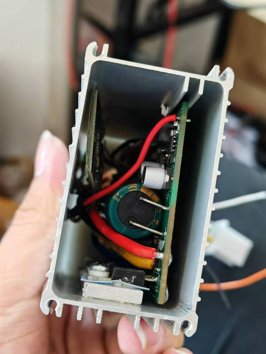
The PCB area is relatively large, and the layout may be somewhat abstract, but the single-sided component layout allows for sparse component placement, easy soldering, and good heat dissipation, facilitating the attachment of heat sinks or a casing on the back. I was lazy and didn't make a casing; four M2 nylon plastic posts for fixing are also acceptable.

Features: The layout is inspired by smart car motherboards. The input interface features a dedicated TO-252 packaged N-channel MOSFET for reverse connection protection and switching, resolving arcing issues upon power-up. R1 and C1 can be left unsoldered. For the 3538 circuit with higher power, a 1770 package inductor is used, while the 3526 uses a 1265 package to minimize inductor heat generation.
Compatibility: The SW3538 pinout is compatible with the SW3518, allowing direct replacement by removing the 5.1K pull-up resistor R9 (tested and confirmed to have no impact).
C1 port protocol: The fast charging protocol of the Zhirong single-chip solution is relatively complete.
C2 and C3 port protocols:
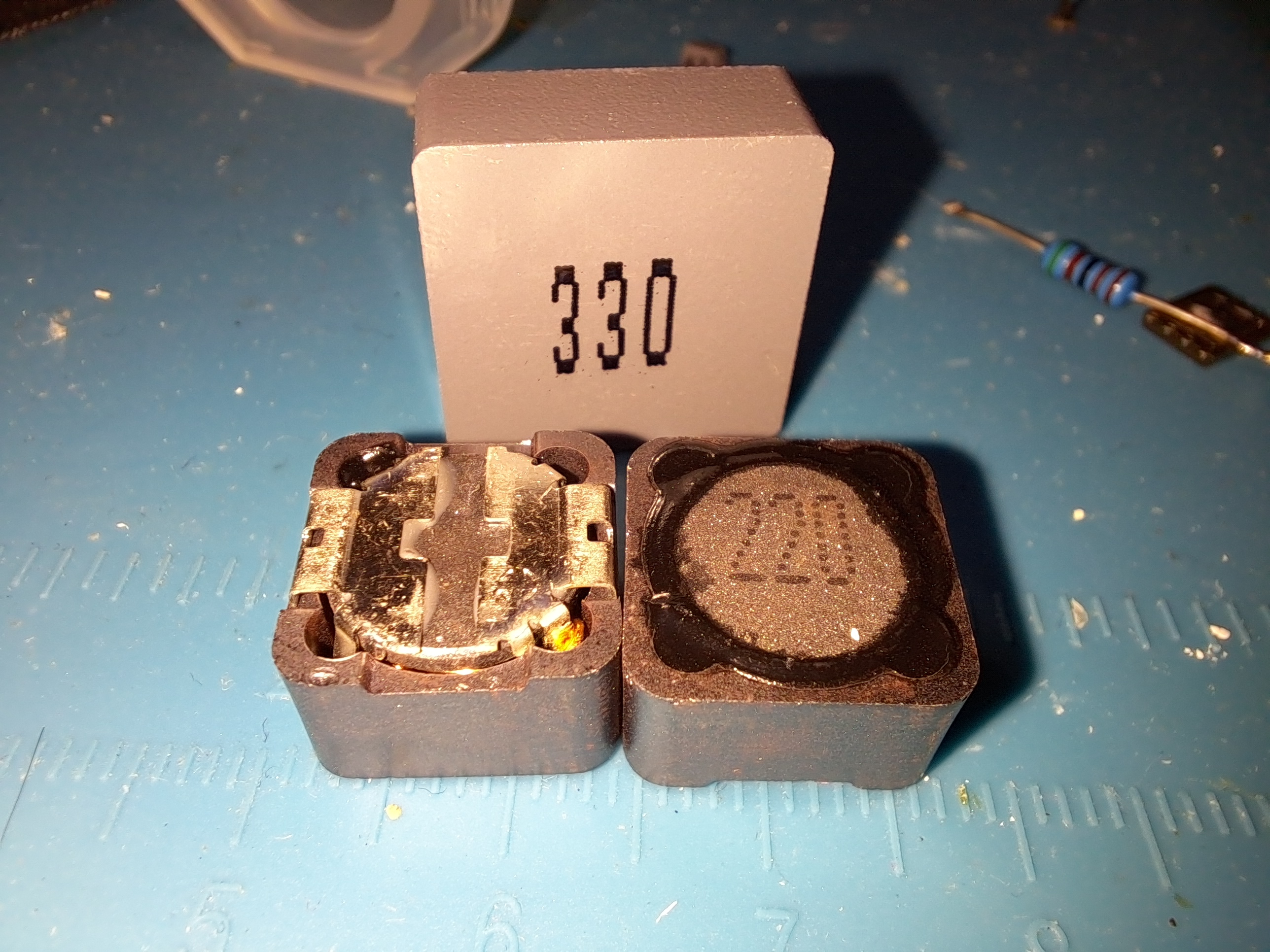
The components already soldered in this diagram are surface-mount; the rest are through-hole components. Close-up of

the three inductors: 1770 package inductors cost 3.5 yuan each, and 1265 package inductors cost less than 1 yuan each.
The sample I have is being tested. The SW3538 uses an AON6144 switch, the output path switch uses an SI7686DP, and the main input reverse connection protection switch is an FQD60N06. The MOSFET junction capacitance is relatively large; at 200W output, the highest temperature is around 50-60 degrees Celsius.
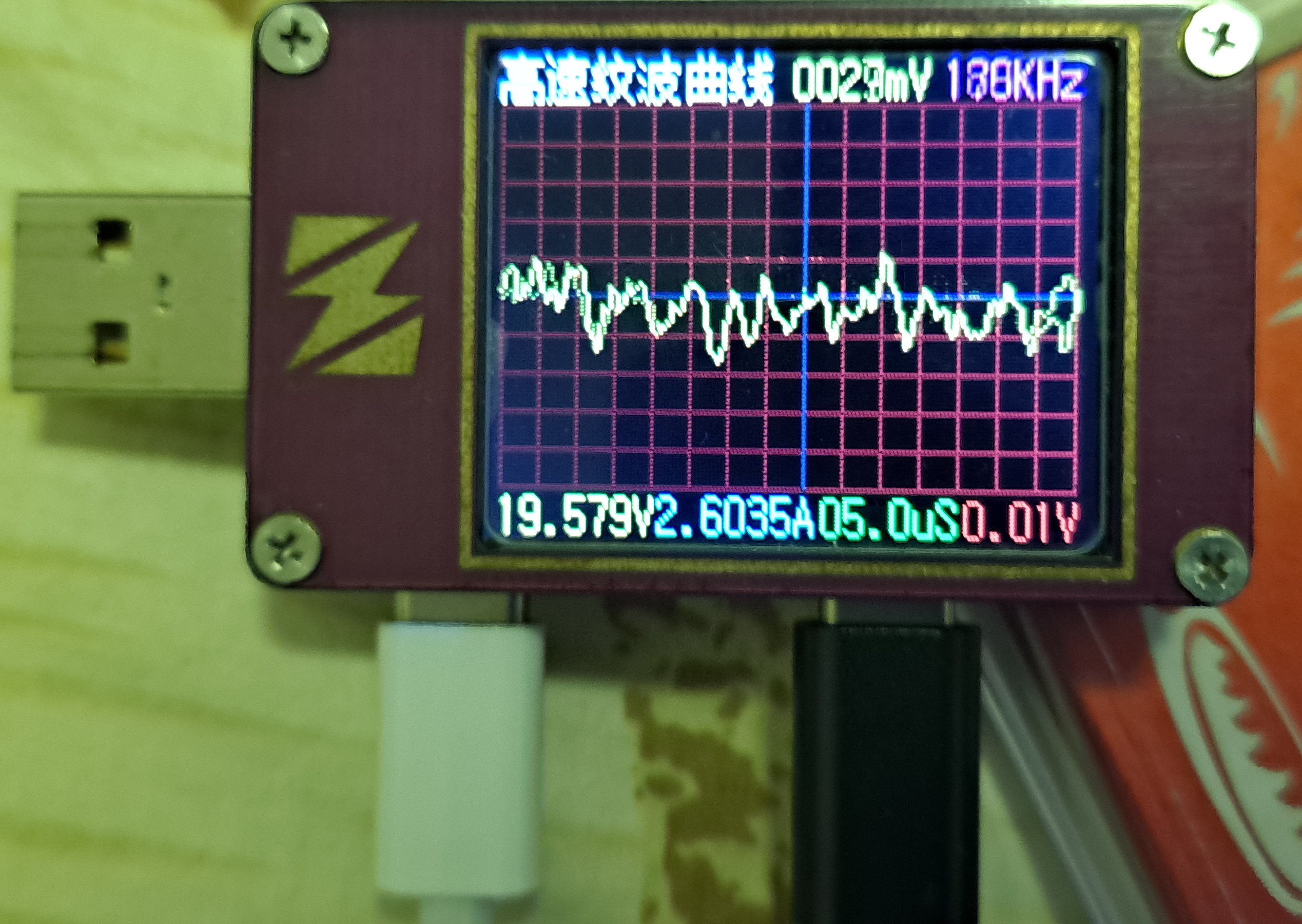
Output stability: Due to the numerous output capacitors, the solid-state + electrolytic + ceramic capacitor filtering effectively reduces the 20V output ripple to below 30mV.
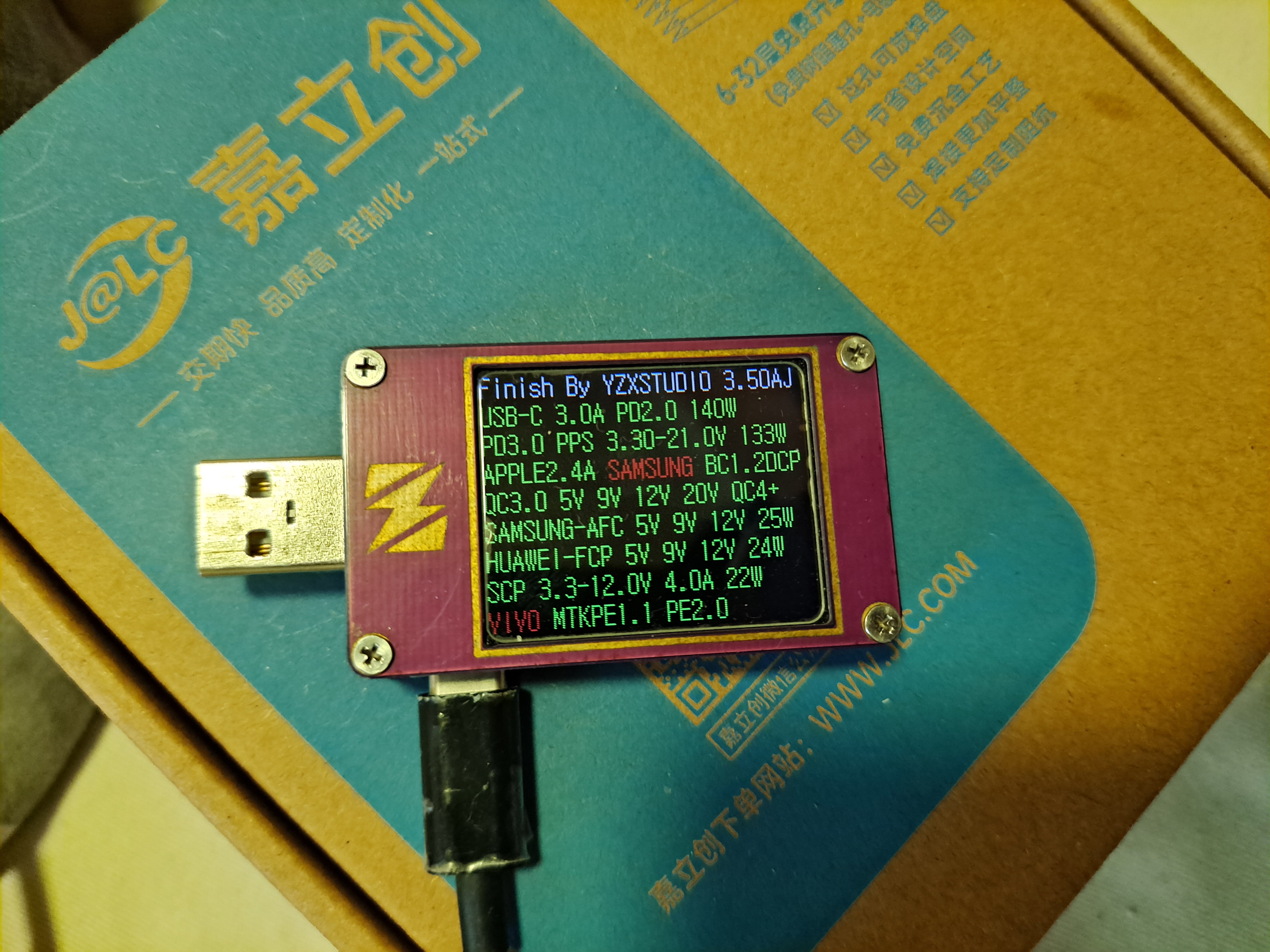
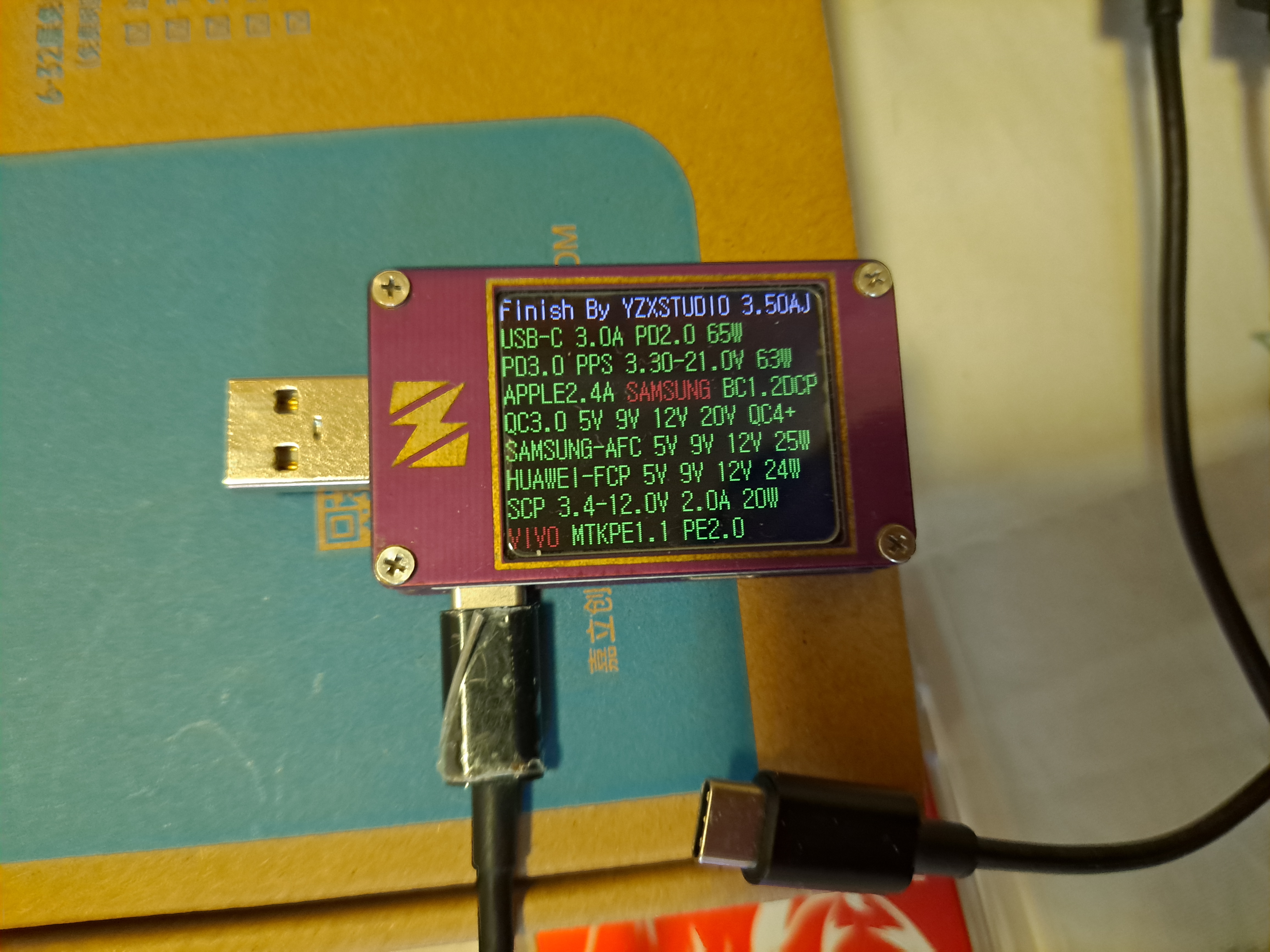
Power testing: The power output is normal according to the USB meter. The highest continuous output at port C1 was tested at around 120W without problems; higher power outputs could not be tested. With a 24V input, the highest measured power of the entire unit was 200W, with an input current exceeding 8.3A. At this point, using a DC5525 input with 18AWG wire resulted in significant heat generation.
It is recommended to switch to an XT60 input for power exceeding 120W, using 14 or 16AWG multi-core copper wire. (Due to equipment limitations, the computer can only reach a maximum input power of around 120W.)

Hardware bug: The fast charging indicator light on the 3538 chip is faulty; the FLED interface cannot be pulled low, causing it to remain off. I've tried two chips with the same issue, so I'm not bothering with it; it doesn't affect usage. The fast charging indicator light on the SW3526 works fine.
Software additional provisions: All three chips have I2C interfaces for connecting a microcontroller to display voltage and current, but I haven't tested it yet. I was a bit lazy with the power supply; I haven't implemented 5V or 3.3V regulation yet. Later, someone can try connecting it to an STM32 or similar microcontroller to see if it works.
Gerber_SW3538+3526_V2.3_2024-09-20.zip
ProProject_SW3518S+3526_V2.3_2024-09-20.epro
PDF_High-power DC step-down charger based on single-channel SW3538S + dual-channel SW3526.zip
Altium - High-power DC step-down charger based on single-channel SW3538S + dual-channel SW3526.zip
PADS High-Power DC Buck Charger Based on Single-Channel SW3538S + Dual-Channel SW3526.zip
BOM_High-power DC step-down charger based on single-channel SW3538S + dual-channel SW3526.xlsx
92016
RM2024 StarCraft 7S3V1890J Supercapacitor Pack
This work is a 7-series 3V60F1890J supercapacitor array used by the Guilin University of Technology-Stars team in the RoboMaster 2024 season.
Document Version: 1.0.2436
> There's not much to say here.
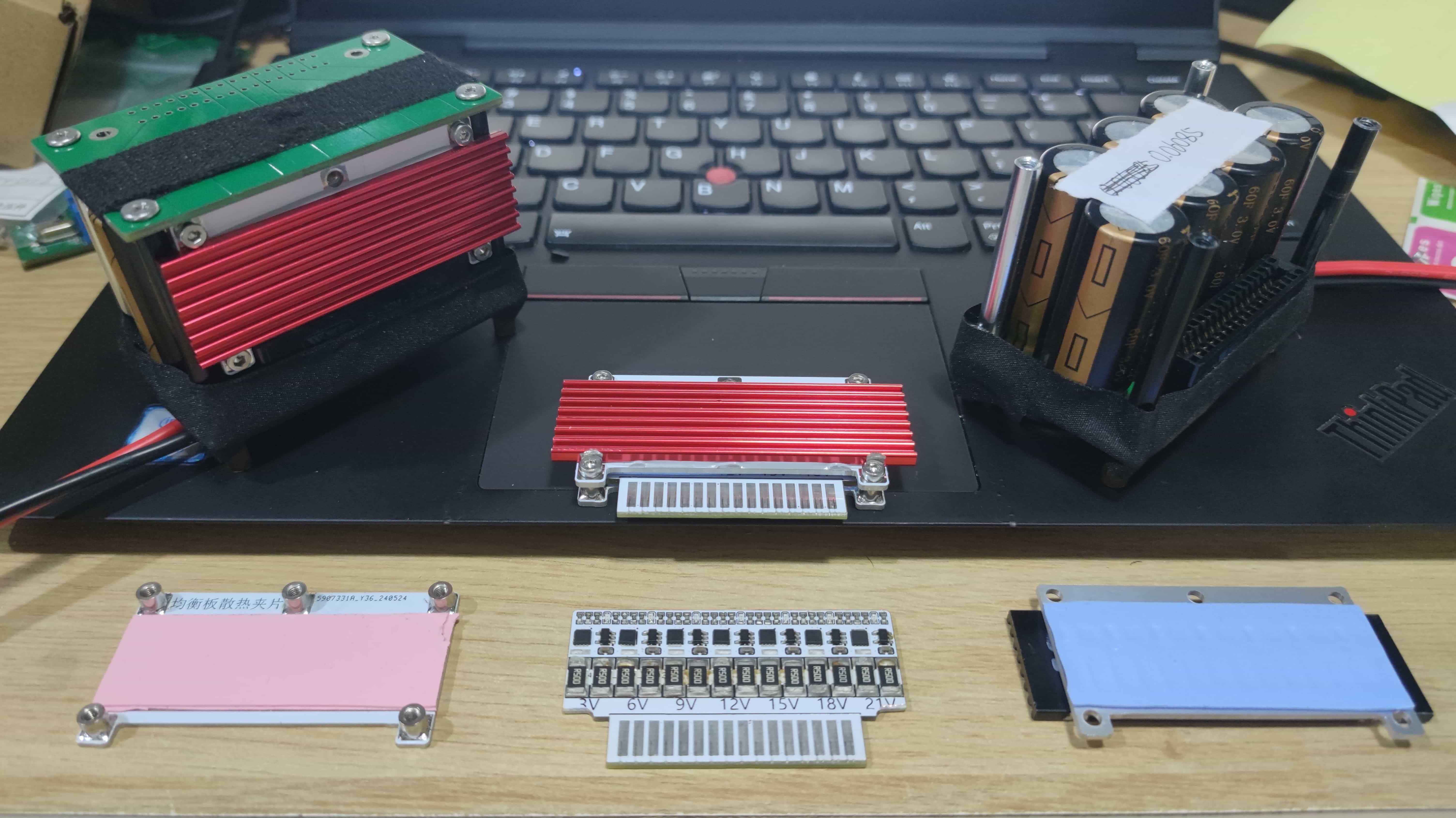
An NTC is placed in the center of the capacitor bank to monitor its temperature. Silicone thermal paste is used to bond it to the three adjacent supercapacitor cells to improve thermal conductivity and reduce thermal hysteresis for more accurate temperature readings.
The equalization board uses a BW6103 chip for passive equalization protection. Due to its relatively small discharge current, an external WSD2050DN is used for current amplification. Two 2512 500mR alloy resistors are connected in series, resulting in a 1R discharge resistor and a discharge current of approximately 3A.
The current-amplifying MOSFET should have a turn-on voltage of around 1.2V to prevent it from failing to conduct. The discharge resistor should not be too small, otherwise it will divide the voltage with the MOSFET, causing the MOSFET to bear excessive discharge power. A too-small discharge resistor will also lead to excessive discharge current and power, which can easily burn out if heat dissipation is poor. **High-temperature solder paste is recommended for soldering.**
The single-string discharge circuit in this design has a loss of 3W, and the 7-string circuit has a loss of approximately 21W. To prevent burnout, a heatsink is added to the discharge equalization board. Under normal circumstances, the capacitor bank should not be in an overvoltage discharge state.
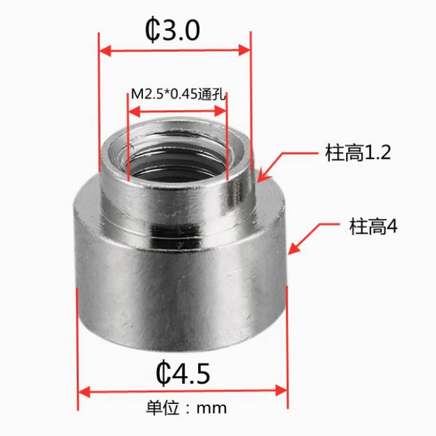
The equalization board heatsink is made using two identical aluminum substrates. One substrate is soldered with five PCB nuts, and the other substrate has a heatsink attached to the opening using silicone thermal paste to increase the heat dissipation area (note that the bolt nuts should be small, otherwise they may jam the heatsink, requiring manual grinding down of the heatsink). Then, 1mm thermal pads are placed on both the front and back of the equalization board (for insulation and heat conduction), and the equalization board is clamped between the aluminum substrates using bolts.
> The heatsink is an M.2 hard drive heatsink, with dimensions of 20*3*70mm; a slightly thicker thickness is acceptable.
> Install the bolts first, then attach the heatsink, as space is somewhat limited; otherwise, a misaligned heatsink may jam the bolts.
Buy smaller bolts and nuts to reduce the chance of them jamming the heatsink.
Use 1mm thermal pads because the overall thickness of the equalization board is approximately 2.5mm, while the PCB nuts are 4mm. The extra 0.5mm allows the aluminum substrate on both sides to apply slight pressure to the thermal pads, resulting in better contact between the thermal pads and the components on the equalization board.
If possible, chamfer the aluminum substrate to make it smoother (or CNC machine it).
If the passive equalization effect is unsatisfactory, an active equalization board can be designed later to replace it.
![SMT Nuts.jpg]
![Equalization Board Interlayer with Text.jpg]

![Family Photo.jpg]
3D model_STEP.zip
PDF_RM2024 All-Stars 7S3V1890J Supercapacitor Pack.zip
Altium_RM2024 StarCraft 7S3V1890J Supercapacitor Pack.zip
PADS_RM2024 Stars Team 7S3V1890J Supercapacitor Pack.zip
BOM_RM2024 Team Stars 7S3V1890J Supercapacitor Pack.xlsx
92017
51 Minimum Development Board | V1.0
STC89C52RC-40I-LQFP44 minimum system board, serial port download, no CH340.
The STC89C52RC-40I-LQFP44 is a minimum system board with Type-C power input, no CH340, and serial port download.
P1.0-P1.2 are LEDs, and P2.0 and P2.1 are independent buttons in the upper right corner. It integrates a 5V to 3.3V converter. The attachment includes an LED movement and blinking test program.
Chip selection: STC89C52RC-40I-LQFP44.
The STC89C52RC is a high-performance microcontroller based on the 8051 core, featuring rich I/O ports, timers, serial ports, and interrupt functions, suitable for various embedded applications.
The LQFP44 package offers more pins, facilitating peripheral expansion and making it suitable for more complex application scenarios.
System board design features:
Power input: Uses a Type-C interface for power input, supporting efficient and stable power supply to ensure the normal operation of the microcontroller and peripheral circuits.
Reset circuit: Includes a reset circuit to ensure the microcontroller is correctly initialized upon power-on or reset.
Crystal oscillator circuit: A suitable crystal oscillator circuit is configured to provide a stable clock signal for the microcontroller, ensuring its normal operation.
Download interface: Since the CH340 is not used for serial communication and downloading, this design directly utilizes the microcontroller's serial port downloading function, programming via a standard serial port.
Test program:
#include
#include
void delay(unsigned int i)
{
unsigned int j;
unsigned char k;
for(j=i;j>0;j--)
for(k=125;k>0;k--);
}
void main()
{ P1=0xfe;
while(1)
{
P1=_crol_(P1,1); //P1 gradually shifts left by one bit.
delay(500);
}
}
0858009560ca48430799fab39759a02.png
8778677e4932f46fbe98d59b985ef71.png
led moving flashing.rar
8a5e32564e1f0a744aa0559e4d3cca38.mp4
PDF_51 Minimum Development Board_V2.0.zip
Altium_51 Minimum Development Board_V2.0.zip
PADS_51 Minimal Development Board_V2.0.zip
BOM_51 Minimum Development Board_V2.0.xlsx
92018
STM32 Matrix Keyboard Calculator!
STM32 Matrix Keyboard Calculator!
Based on the STM32F103RCT6 development board. The development board itself is not provided
; you can use DuPont wires or replace it with other development boards
(just modify the PCB, pins, etc.) to achieve the desired result
! There might be many bugs, so please be gentle with your criticism.
This STM32 matrix keyboard simple calculator
demonstration video
is requested to be liked, commented, and shared.
The hardware
components
include a custom PCB design by JLCPCB and
an STM32F103RCT6 chip
. Essentially, this project is just a matrix keyboard expansion board,
but the code is for a calculator and it works.
The structure is largely the same as others, except the interface locations correspond to those in this open-source project. You
can use your own development board with DuPont wires
or modify it to integrate the chip directly.
The matrix keyboard expansion board
hardware is based on the open-source project SCICAI, using an STM32 controller. Of course, it's not as
advanced as the original.
The STM32 development board consists of several modules: interface
communication download module,
matrix keyboard module,
battery management module,
lithium battery boost module , and
Type-C interface
. See the schematic and PCB for details.
The software (standard library) includes
a calculation
algorithm using postfix notation (Reverse Polish Notation),
encompassing functions for converting expressions to postfix notation, error checking, and calculation.
It can perform trigonometric functions, logarithmic functions, ln functions, exponentiation, and square root calculations.
The matrix keyboard scanning algorithm
uses row-by-row scanning, with 8 checks performed in the software (each with a 2ms interval). Level debouncing is implemented.
The UI design

, based on the u8g2 library,
is divided into three parts: a status bar, an expression bar, and a result bar.
The status bar displays a
CAL status indicator. (I originally wanted to add other functions, but I was too lazy to do it, haha.)
The Shift key is indicated by a vertical bar, which shows the Shift key is locked. The
left and right arrow keys indicate whether the expression is hidden before or after it, and the vertical arrow keys are for history, but I'm too lazy to type them out, haha.
The expression only shows the cursor, which can be moved using the left and right arrow keys on the matrix keypad.
The result display shows the calculation result and error information; it can scroll when the result is too long.
Other software includes serial port and RCC software, which I won't go into detail about.
A software structure diagram is attached below.

Calculator.zip
PDF_STM32 Matrix Keyboard Calculator! .zip
Altium_STM32 Matrix Keyboard Calculator! .zip
PADS_STM32 Matrix Keyboard Calculator! .zip
BOM_STM32 Matrix Keyboard Calculator! .xlsx
92019
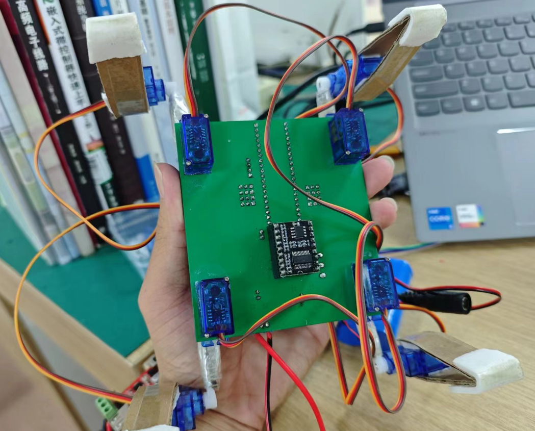
Voice-controlled mechanical four-jaw jack based on the DiKuoXing (STM32F103C8T6)
This expansion project, based on the Dikuoxing core board, utilizes voice control and is battery powered.
Project Overview:
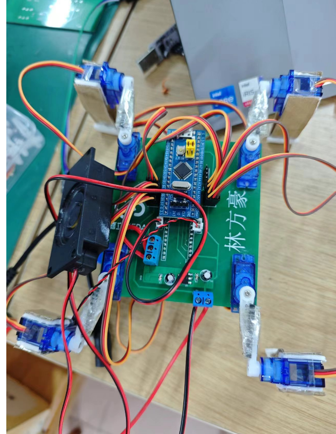
This project is an extension project based on the LCSC Dikuoxing core board, using 8 SG90 servos and an ASR PRO voice recognition control module. The expansion board
for
the four robot groups has servo interfaces, a 0.96-inch OLED display interface, a voice control chip interface, a microphone, and a speaker interface; enabling voice control of the robot's movements.
Project Parameters
: 1. This design uses the LCSC Dikuoxing core board (STM32F103C8T6).
2. ASR PRO voice control module, which uses Tianwen Block programming; if you have your own components, you can integrate the module onto the expansion board.
3. Eight SG90 servos. 4.
0.96-inch display screen; the expansion board has interfaces, but this project does not currently use it.
5. AMS1117 linear regulator 5V to 3.3V circuit
principle analysis (hardware description):
I. AMS1117 linear regulator circuit:

This circuit takes a 5V power supply as input and outputs a stable 3.3V to power the microcontroller.
II. 12V power supply step-down 5V module:
This module can be purchased arbitrarily and mainly powers the servos. Note that when connecting to the expansion board, thicker wires are needed. DuPont wires cannot withstand the current after converting 12V to 5V and will burn out the DuPont wires (already tested...).
III. ASR... The PRO module

interface is on the bottom. If you want to solder it on top, swap the two pin headers on the PCB. Pay attention to the corresponding pins. See the attached

software code for notes: I. My servo motor pin connection instructions ; II. Servo motor wiring and assembly process. The legs of this quadruped robot are made of tape and glue combined with cardboard (you can 3D print them yourself if you don't want to, but I don't know how to 3D draw yet). [ Image of the actual product ]


1.mp4
2.mp4
Mechanical Quadruped Code.zip
Language Control.hd
PDF_Voice-Controlled Mechanical Four-Jaw Machine Based on DiKuoXing (STM32F103C8T6).zip
Altium-based voice-controlled mechanical quad-jaw jack (STM32F103C8T6).zip
PADS_Voice-Controlled Mechanical Four-Jaw Based on DiKuoXing (STM32F103C8T6).zip
BOM_Voice-Controlled Mechanical Quadruple Gripper Based on DiKuoXing (STM32F103C8T6).xlsx
92020
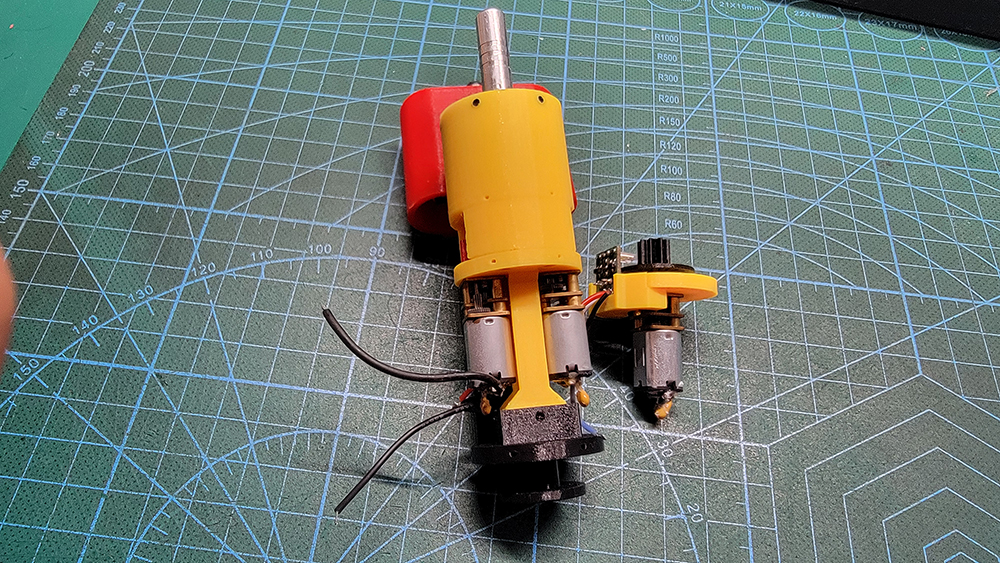
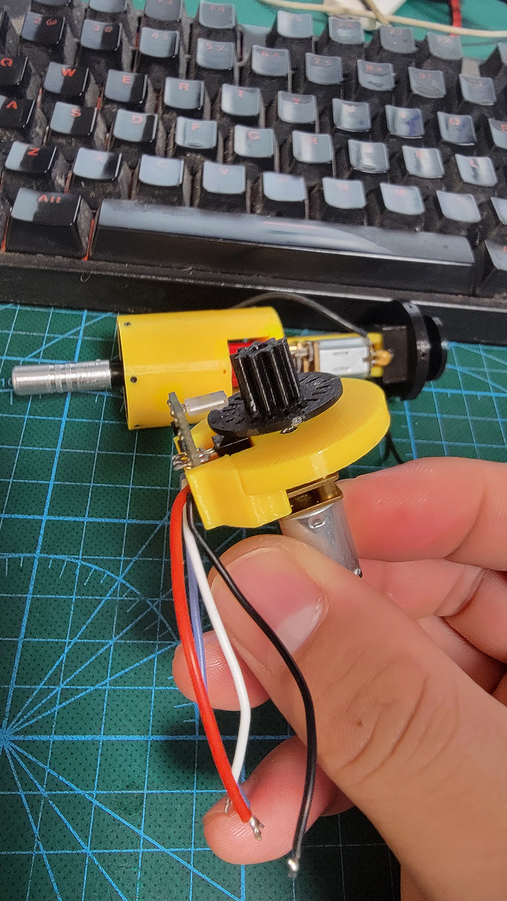
N20 motor encoder
The N20 encoder is a bit pricey, but buying the N20 motor itself is much cheaper. By using a homemade encoder and code disk, and with the help of a 3D printer, you can easily create an encoder-motor hybrid. The circuit cost is less than 1 yuan.
PDF_N20 Motor Encoder.zip
Altium_N20 motor encoder.zip
PADS_N20 motor encoder.zip
BOM_N20 Motor Encoder.xlsx
92021
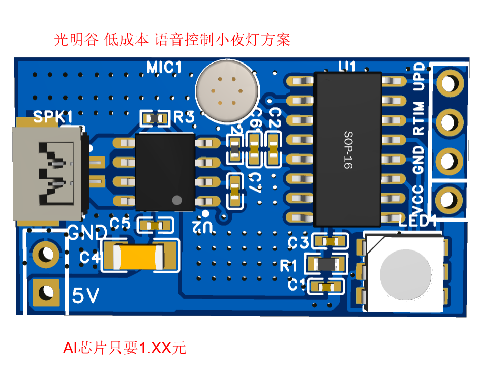
VS-S100D Low-Cost Smart Voice-Controlled Night Light Solution
Guangming Valley has launched the VC-S100D low-cost voice-controlled night light solution. Users can own it without any development. We have a mature solution that allows users to quickly create a voice-controlled night light without development (zero code). We provide schematics, PCB demos, and PCB layout guidance.
Solution Overview:
Guangming Valley presents the VC-S100D low-cost voice-controlled night light solution. Users can own it without development. We have a mature solution that allows users to quickly complete voice-controlled night lights without development (zero code). We provide schematics, PCB demos (LCSC open source, zero-code development and replication, worth having), and PCB layout guidance.
Solution Advantages:
Low cost, IC cost as low as 1.XX RMB in batches.
Includes echo playback,
RGB full-color night light control,
color temperature (warm and cool colors)
, built-in high-performance 160MHz RISC-V CPU + NPU + DSP
(customizable
), built-in PMU (power management unit), eliminating the need for LDO
, extremely simple peripheral circuitry (only 1 mic, 2 surface-mount capacitors), and extremely low BOM cost.
System Framework

Demo Board Diagram
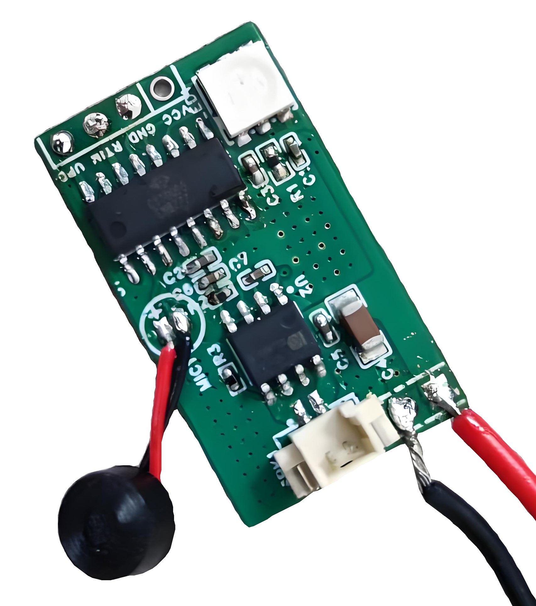
IC Introduction:
The S100D is a highly integrated offline voice recognition IC with built-in 32-bit RISC-V + DSP + NPU.

Features and Parameters:
CPU and Flexible IO:
High-performance 160MHz RISC-V CPU + NPU + DSP;
All IOs support push-pull output with built-in pull-up/pull-down configuration;
All IOs support sleep/wake-up; Power Supply
: 2~5.5V;
RAM: 52KB;
ROM: Flash 4 Mbits (512KB);
DAC: Stereo;
ADC: Mono;
Package: SOP16;
Temperature Characteristics
: Operating temperature: -40℃ to +85℃; Storage temperature: -65℃ to +150℃;
Typical Applications : Voice
control for nightlights ; Voice control for RGB light strips; Voice control for smart desk lamps; Voice control for home appliances ; Voice control for RGB bulbs; Voice control for lighting equipment ; Smart toys . PCB Description : Function Introduction : Voice recognition controls RGB nightlights or light strips to turn on and off ; Voice recognition controls RGB nightlights or light strips to change colors; Voice recognition controls RGB nightlights or light strips to change color temperature (warm or cool); Timed shutdown of RGB nightlights or light strips; Reply tone playback; DAC output; Amplification and MUTE control. RGB LED GPIO: 3-channel PWM control, high voltage effective. For details, please refer to the schematic diagram. Voice command definition: Number | Command | Action 01 | Turn on light: Please turn on the light | Turn on the light (RGB LED GPIO: 3-channel PWM, 80% utilization) (Announcement: Light is on) 02 | Turn off light: Please turn off the light | Turn off the light (Turn off all lights) (Announcement: Light is off) 03 | Brighten: Brighten a little | Brighten a little (RGB LED GPIO: 3-channel PWM control, increase duty cycle by 5%, maximum 100%) (Announcement: Light is brightened) 04 | Dim: Dim a little | Dim a little (RGB LED GPIO: 3-channel PWM control, decrease duty cycle by 5%, minimum duty cycle 5%) (Announcement: Light is dimmed) 05 | Brightest: Maximum brightness | Brightest light (RGB LED GPIO: 3-channel PWM, 100% utilization) (Announcement: Light is brightest) 06 | Dimmest: Minimum brightness | Dimmest light (RGB LED GPIO: 3-channel PWM minimum duty cycle 5%) (Announcement: Light is now at its dimmest) 07 Color Command: Change Color | Change Color (White-Yellow-Red-Blue-Green-Cyan-Violet, cycling through colors in sequence) (Announcement: Light color has changed) 08 White Command: Change to White | Change to White Light (White LED GPIO: 1-channel PWM; RGB LED GPIO: 3-channel PWM, 80% usage) (Announcement: Light has been adjusted to white) 09 Yellow Command: Change to Yellow | Change to Yellow Light (RGB LED GPIO: 3-channel PWM adjusted to yellow) (Announcement: Light has been adjusted to yellow) 10 Warm Color Command: Change to Warm Color | Change to Warm Light (RGB LED GPIO: 3-channel PWM adjusted to warm yellow) (Announcement: Light has been adjusted to warm yellow) 11 Red Command: Change to Red | Change to Red Light (RGB LED GPIO: 3-channel PWM adjusted to red) (Announcement: Light has been adjusted to red) 12 Red Command: Change to Green | Change to Green Light (RGB LED GPIO: 3-channel PWM switched to green) (Announcement: Lights switched to green) 13 Blue command: Change to blue | Change to blue light (RGB LED GPIO: 3-channel PWM switched to blue) (Announcement: Lights switched to blue) 14 Cyan command: Change to cyan | Change to cyan light (RGB LED GPIO: 3-channel PWM switched to cyan) (Announcement: Lights switched to cyan) 15 Purple command: Change to purple | Change to purple light (RGB LED GPIO: 3-channel PWM switched to purple) (Announcement: Lights switched to purple) 16 Timer for 15 minutes command: Timer for 15 minutes (Timer off all lights) (Announcement: Timer for 15 minutes) 17 Timer for 30 minutes command: Timer for 30 minutes (Timer off all lights) (Announcement: Timer for 30 minutes) 18 Timer for 60 minutes command: Timer for 60 minutes (Timer off all lights) (Announcement: Timer for 30 minutes) Download Data

Voice-controlled night light solution VC-S100D schematic and PCB file download_Data Download_SUNSHINE SILICON (sunsili.com)
Video demonstration:
Due to size limitations, please go to [link to video].
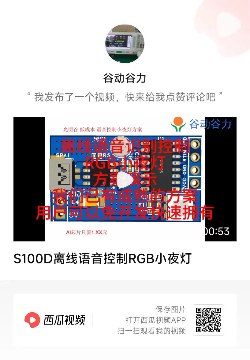
S100D Voice-Controlled RGB Night Light.mp4
PDF_VS-S100D Low-Cost Smart Voice-Controlled Night Light Solution.zip
Altium_VS-S100D Low-Cost Smart Voice-Controlled Night Light Solution.zip
PADS_VS-S100D Low-Cost Smart Voice-Controlled Night Light Solution.zip
BOM_VS-S100D Low-Cost Smart Voice-Controlled Night Light Solution.xlsx
92022
electronic


 京公网安备 11010802033920号

 4540EX103M9


