Important Notes:
This project is geared towards sharing and exchanging experiences. Due to the following reasons, replicating this project is not recommended. If you do need to replicate this debugger or enjoy tinkering but don't want too much hassle, we recommend these two projects with fewer pitfalls: [Verified] EV2400-Economy Based on MSP430F5529 - LCSC Open Source Hardware Platform (oshwhub.com) and [Verified] EV2400-Lite Based on MSP430F5529 - LCSC Open Source Hardware Platform (oshwhub.com).
1. MSP430F5528 chips below 20 RMB on Taobao are almost never genuine; most are refurbished. My friend and I bought a total of 7 different MSP430F5528 chips from different sellers. Some couldn't be used after flashing the program, some couldn't access USB-BSL, some had no crystal oscillation, and some even didn't output VCORE voltage.
2. According to the advice of experts in the group, MSP430F5528 chips with disassembled boards from a certain online marketplace can be used. However, this marketplace is notorious for its mixed quality of vendors and unreliable practices. While it is indeed usable after testing, the success rate of replication cannot be guaranteed.
3. I personally purchased several MSP430F5529 LaunchPad development boards used in electronics design competitions. These boards include eZ-FET-Lite for programming the MSP430F5529, and the main controller is the 5528. This ensures they are official genuine products. However, I cannot flash the firmware using the EV2400 upgrade program in USB-BSL mode. The specific reasons are mentioned below.
4. Different system versions also affect the success rate of replication. The specific reasons are also mentioned below.
Schematic & PCB Design
1. This 2400 is the earliest version I wanted to create, but I encountered a lot of problems. After communicating with experts, I understood many issues and finally succeeded.
2. The schematic is modified from the official EV2400. @XDZZ suggested that the 5528 could replace the 5529, so the 5528 was used instead. The 5528 has all the main data exchange pins used by the EV2400, and both the 5528 and 5529 are from the same series with identical cores. The only difference is some peripherals and packages. The program files are fully usable.
3. The level conversion IC is slightly different from the one used by TI. TI's is harder to find, so a domestic one was used instead. The datasheet specifies a lower speed than the original, but it works fine in tests.
4. The PCB design is a bit large, mainly because I was too lazy to modify the casing model file and directly used a previously made casing.
Debugging & Firmware Flashing
1. After testing, most of the disassembled/cut MSP430F5528 boards (early stock) sold by sellers on Xianyu (a second-hand marketplace) can enter USB-BSL mode normally and can be recognized by the update software and complete firmware flashing. Since this project is mainly for discussion, please refer to the project: [Verified] EV2400-Lite Based on MSP430F5529 - LCSC Open Source Hardware Platform (oshwhub.com) for specific firmware flashing steps.
2. Use the eZ-FET-Lite programmer with UniFlash software to extract the firmware from the MSP430F5529 already flashed with EV2400 (the firmware is attached below) and flash it to the MSP430F5528 (requires the eZ-FET-Lite programmer, whose main controller is also MSP430F5528; I have also prototyped and open-sourced a version: [Verified] eZ-FET-Lite Debugger/Flasher - The process for using the LCSC open-source hardware platform (oshwhub.com) is as follows:
(Most of this text is copied from @hexesdesu, thank you!)
Find a programmer capable of programming the 5528 chip. The LaunchPad's onboard eZ-FET-Lite or FET430UIF will work. Connect it to the prepared board using the following connection method: SBW-RST --> RST; SBW-TST --> TEST; 3V3 --> 3.3V; GND --> GND.
Install the UniFlash tool on your computer.
Download the firmware package from the attachment; any of the three firmware options are acceptable.
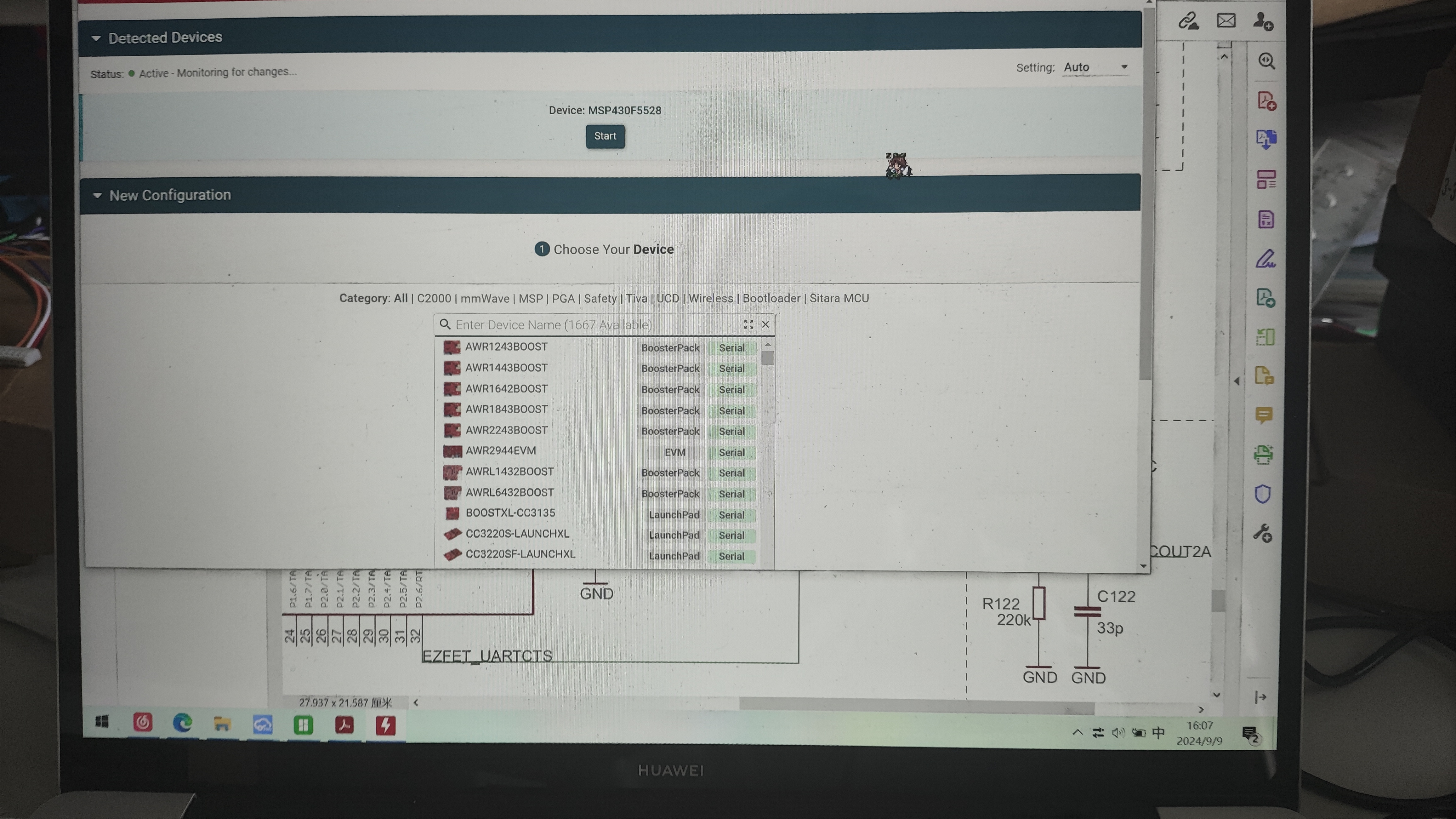
Open UniFlash, select the MSP430F5528 chip and connector. The first connector should be selected by default. (For the current version, there's an auto-detection option at the top. If auto-detection is enabled and the programmer is properly connected to the microcontroller, it will automatically recognize the target microcontroller. Just click on it (as shown in the image, simply click START to enter).)
On the Settings & Utilities page, find the Erase section and click Mass Erase. Wait for the erase to complete. (Do not click EraseByAddress. If you are using firmware with addresses 0x00-0x243ff or 0x4400-0x243ff as shown below, you can enter those addresses in Start and EndAddress to perform a full erase.)
In the Download section above, check Allow Read/Write/Erase access to BSL memory. Return to the Program page,
select the firmware you just copied in Flash Image(s), and click Load. After uploading the firmware to Image and waiting for a successful upload notification
, disconnect the burning cable and plug the EV2400-F5528 with the burned program into the computer. At this time, the three signal indicator lights will light up first and then go out, indicating that the computer recognizes the EV2400. The reported VID-PID is normal and can be recognized by the upgrade software.
3. The following describes the pitfalls encountered during the creation of this version and their solutions:
Homemade EV2400 debugger, problem-solving steps and cause analysis:
1. No response after plugging in USB and powering on:
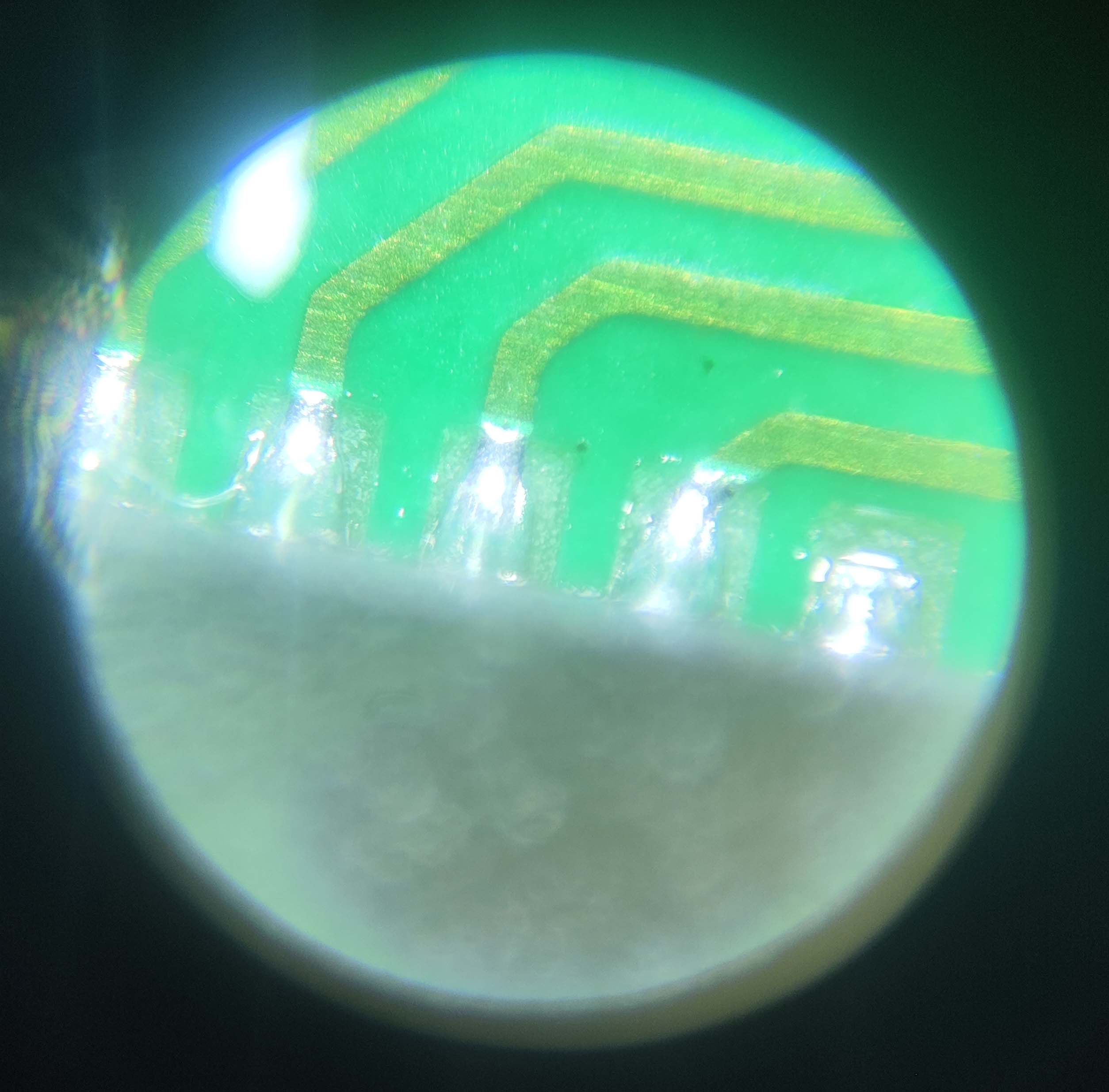
This is generally a soldering problem; 5529 is relatively easy to solder, but 5528 QFN is more difficult to solder, and LCSC's package is not a hand-soldered package, the exposed copper on the pins is very small, making it difficult to solder with a soldering iron. It is recommended to use a heating table + solder paste kit, and use a soldering iron to clean up excess solder balls and bridging. You can buy a monocular microscope for 20-30 RMB on Pinduoduo to check the pin status, which is quite useful (as shown in the picture).
After confirming that the soldering is correct, you can measure the voltage of the VCORE pin. It should normally be around 1.8V. If there is no voltage, congratulations, you have bought a defective chip. Quickly contact the seller to argue. If you bought it on Taobao, directly contact the official customer service to apply for a refund, on the grounds that you sold a scrap chip and the official software cannot recognize it. There is a high probability that you can get a refund.
If the VCORE has voltage, the crystal oscillator might not be oscillating. Don't believe any crystal oscillators on Taobao that claim to be genuine Murata parts. Crystal oscillators taken from the official MSP430F5529 LaunchPad development board work without matching capacitors. The ones I bought from Taobao, from three different vendors, all required load capacitors; otherwise, they wouldn't oscillate. The silkscreen markings were completely different from those on the official development board, so they weren't genuine.
If you have an oscilloscope to confirm oscillation, try shorting R6 for a long time while plugging the device into the computer's USB port. You should get a device insertion but not recognized message; otherwise, the USB connector's soldering or quality is faulty.
2. No device insertion beep on the computer (unable to enter USB-BSL mode).
If the USB interface soldering is confirmed to be fine after testing, the problem is usually due to improper shorting. This is my fault; it's difficult to short-circuit properly using the resistor pad method. I suggest using pointed tweezers, or using two wires to connect to a button. It could also be caused by excessive shorting time. Shorting only needs to be completed about one second after pressing the reset button. You can short-circuit first, then press the reset button, and release it for about one second before removing the shorting.
3. If you can enter BSL mode but the burning software crashes (the software doesn't recognize it),
this is because the software doesn't recognize the corresponding VID-PID. The reasons are as follows:
1. System issues (thanks to @3598abc). Try inserting the TYPC connector several times and use VID-PID detection software (attached). The PID and VID will change; sometimes VID0200 PID2047 is normal, and the LED will flash. The upgrade program and BQ software are normal. In a WIN7 32-bit system, both PID and VID will appear randomly (you can check the PID and VID in Device Manager). No issues were found on Windows 10 64-bit. Check the PID and VID in Device Manager. If the PID is 2047 and the VID is 0200 (LED flashing), it's normal. (The TYPC connector on the small board inserts normally when inserted slowly, but fails when inserted too quickly; I don't know why.)
2. Possible IC version issue. I bought several MSP430F5529 LaunchPad development boards used in the electronics design competition. They have eZ-FET-Lite for programming the MSP430F5529, and the main controller is 5528. This ensures they are official genuine products, but I cannot flash the firmware in USB-BSL mode using the EV2400 upgrade program. However, when I checked the official BSL manual, I found that the manual says the PID-VID reported by USB-BSL should be 2047-0200, but the actual test showed 2047-0203. Considering that the cases reporting usable USB-BSL are all early disassembled ICs, it may be because the firmware of the early ICs is different from that of the new ICs, or it may be because the LaunchPad has a BSL button for the 5529, and to prevent conflicts, the BSL firmware of the 5528 on the LaunchPad is a special firmware with a modified VID.
Currently, I'm considering reverse engineering the upgrade program provided by TI to modify the VID-PID to be recognized, thus enabling the flashing of various VID-PIDs.
A note at the end:
Nothing else is too complicated. If you encounter any problems, feel free to contact me for discussion; I'll reply as soon as possible.
The extracted firmware is attached, which you can flash directly. A VID-PID viewer is also provided to see where you're stuck. If you've read this far, please give it a like!
While writing this, I was thinking of flashing the BSL from the 5529 to the 5528, but it resulted in a 555 being locked (;´д`).


 京公网安备 11010802033920号

 MI-P7N3-IYZ


