
 2. NXP's RF antenna design
  3. Convert the schematic to a PCB. Add the image you want to draw on the PCB to the document layer, adjust the expected size, and enter the coil size you can design in the Excel file mentioned earlier. Note that this should not exceed JLCPCB's processing capabilities. Adjust the component positions. I expect the flower above the coil to light up when it's near the coil (also for easy testing of functionality after soldering).
  4. Connect the circuitry. Place the drawn coil on one side of the PCB.
 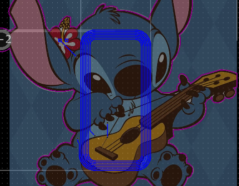 5. Draw the outline. In the board outline layer, select polyline, and draw the arc according to the edge of the selected image. Refer to the video at https://b23.tv/t66PeZp.
  7. Download NXP's writing software, TagWriter, from the NXP website (the chip needs to be formatted before use; click the Clear Tag button - Erase and Format to NDEF).
 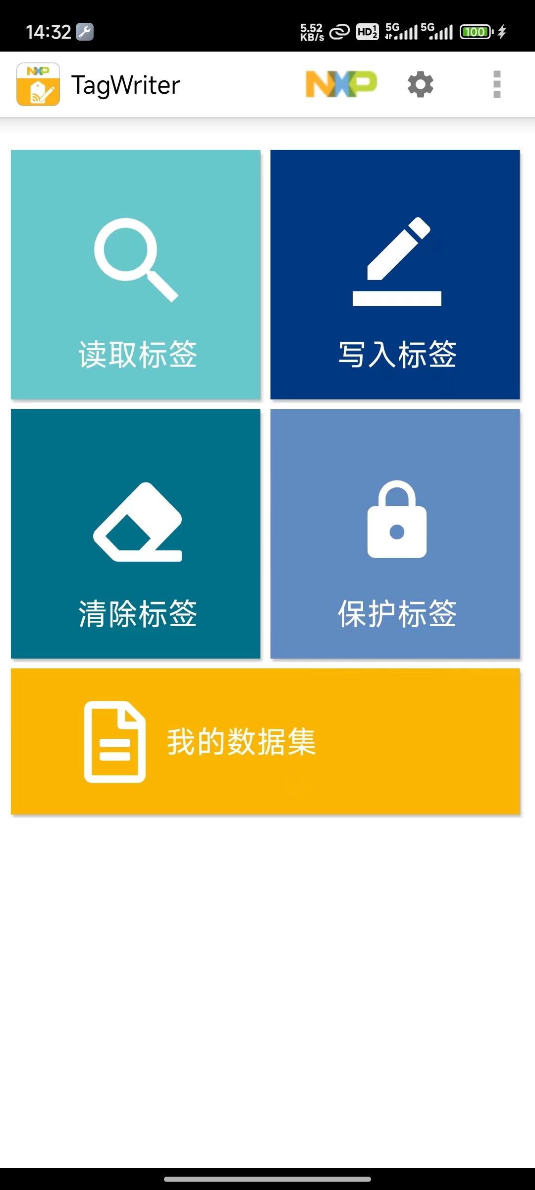 8. Click Write Tag, follow the prompts, and you'll have a fun Stitch keychain!
  (Stitch image from the internet; please contact me to remove it if there is any copyright infringement.)

All reference designs on this site are sourced from major semiconductor manufacturers or collected online for learning and research. The copyright belongs to the semiconductor manufacturer or the original author. If you believe that the reference design of this site infringes upon your relevant rights and interests, please send us a rights notice. As a neutral platform service provider, we will take measures to delete the relevant content in accordance with relevant laws after receiving the relevant notice from the rights holder. Please send relevant notifications to email: bbs_service@eeworld.com.cn.
It is your responsibility to test the circuit yourself and determine its suitability for you. EEWorld will not be liable for direct, indirect, special, incidental, consequential or punitive damages arising from any cause or anything connected to any reference design used.
Supported by EEWorld Datasheet
EEWorld
subscription
account

EEWorld
service
account

Automotive
development
community

Robot
development
community

About Us Customer Service Contact Information Datasheet Sitemap LatestNews


Room 1530, 15th Floor, Building B,
No.18 Zhongguancun Street,
Haidian District,
Beijing, Postal Code: 100190
China
Telephone: 008610 8235 0740
 京公网安备 11010802033920号

 ST303C1111


