Video Link:
See attachment and Bilibili link for details:
https://www.bilibili.com/video/BV1QytaegEqN/?vd_source=e36622a05269c0356d6cd566056a2488
Project Introduction:
This project is a temperature and humidity meter based on the LCSC ESP32-S3 development board. It has temperature and humidity detection and alarm functions, as well as voltage measurement functions.
Project Functions
: This design is a temperature and humidity alarm system based on the LCSC ESP32-S3 development board; it has
4 independent buttons;
3 independent indicator lights;
1 voltage measurement interface;
alarm sound and corresponding alarm light indication.
Project Parameters:
This design uses the ESP32-S3 chip, a dual-core processor with a main frequency of up to 240MHz;
it uses an OLED LCD display to show the current temperature and humidity;
it selects the SHT40 fully digital temperature and humidity sensor, which has a wide temperature measurement range and can meet general needs;
when the temperature or humidity exceeds the threshold range, a buzzer alarm will sound and a corresponding LED alarm light will illuminate;
voltage can be measured via buttons, with a measurement range of (0-20V).
Hardware Description:
This project consists of the following parts: main control unit, button unit, buzzer unit, and LED indicator unit.
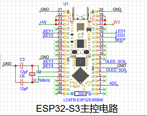
Main Control Unit Description:
The LCSC ESP32-S3 development board is a high-performance development board based on the ESP32-S3 chip, with rich functions and features, making it very suitable for applications in the fields of IoT and embedded development.
I. Chip and Performance
: Core Chip: The core chip is the ESP32-S3 chip, which integrates an Xtensa® 32-bit LX7 dual-core processor with a main frequency of up to 240MHz and built-in 512 KB SRAM (TCM), providing powerful computing capabilities for complex data processing and multi-task execution.
AI Acceleration: The ESP32-S3 adds vector instructions for accelerating neural network calculations and signal processing. Through the ESP-DSP and ESP-NN libraries, high-performance image recognition, voice wake-up, and recognition applications can be easily implemented.
II. Communication and Connectivity
: Wireless Connectivity: Supports Wi-Fi and Bluetooth 5 (LE) dual-mode communication, reducing the difficulty of device network configuration. It also supports Bluetooth Mesh and Espressif Wi-Fi Mesh protocols, enabling higher communication stability and wider coverage.
Multiple Interfaces: Features 45 programmable GPIO pins and rich communication interfaces such as SPI, I2C, and UART, facilitating connection and expansion with various peripherals.
III. Special Features
: Power Management: Some development boards may integrate a power management module, supporting lithium battery charging and hardware power on/off, providing a more convenient power management solution.
Onboard Camera Interface: Some development board models have an onboard camera interface with an independent camera power supply circuit, reducing interference from other signals and facilitating image processing and video transmission applications.
Vibration and Haptic Sensing: Some development boards also incorporate smartphone-like human-computer interaction vibration and haptic sensing functions, using a vibration motor to drive the chip and achieve a richer interactive experience.
IV. Development Tools and Supported
Development Environments: Supports multiple development environments such as Arduino IDE, ESP-IDF, and MicroPython. Developers can choose the appropriate development tools according to their preferences and needs.
Examples and Tutorials: The official website provides a wealth of examples and tutorials to help developers quickly get started and develop projects.
Technical Support: LCSC and its partners provide multi-channel technical support, including official forums, code repositories, and technical exchange groups, making it convenient for developers to seek help when encountering problems.
V. Applicable Scenarios:
The LCSC ESP32-S3 development board is suitable for various scenarios, including but not limited to:
IoT device development: such as smart homes, smart security, smart wearables, etc.
Embedded system development: such as industrial automation, agricultural automation, intelligent transportation, etc.
AI and machine learning applications: such as image recognition, speech recognition, natural language processing, etc.
The pins and design used in this project are as follows:
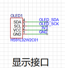
OLED Display :
The HS91L02W2C01 display is an OLED display with various characteristics and application scenarios.
Basic Parameters
: Size: 0.91 inches
; Pixel Resolution: 128x32;
Interface Type: I2C;
Dimensions: 38*12 (units may be in millimeters, but the specific unit needs to be confirmed with the actual product or datasheet);
Operating Temperature: -40℃~+70℃, indicating that the display can operate normally within a wide temperature range.
Technical Features
: OLED Technology: OLED (Organic Light Emitting Diode) displays have self-emissive characteristics, enabling higher contrast and a wider color gamut, while also having faster response time and lower power consumption.
I2C Communication: Communication via the I2C interface allows the display to easily connect to various microcontrollers or processors for data transmission and control.
Black Background with White Light: The black background with white light display method makes the display effect clearer and brighter, suitable for various visual environments.
Application Scenarios
: Electronic Product Display: Due to its small size, low power consumption, and excellent display effect, the HS91L02W2C01 display is very suitable for the display interface of various electronic products, such as smartwatches, smart bracelets, and portable medical devices.
Industrial Control: In the field of industrial control, this display screen can be used to show equipment status, parameter settings, and other information, helping users to understand and control equipment more intuitively.
Other Fields: In addition, this display screen can also be applied to smart homes, automotive electronics, security monitoring, and other fields, providing users with convenient display solutions.
Precautions:
When using the HS91L02W2C01 display screen, it is necessary to refer to its datasheet or related documents to ensure correct connection and configuration.
The display effect and performance of the screen may be affected by various factors such as the usage environment and drive circuit, therefore, appropriate testing and adjustment are required in practical applications. The SHT40
temperature and humidity sensor
is a high-precision, low-power digital temperature and humidity sensor launched by Sensirion, Switzerland, belonging to the Sensirion SHT4x series.
I. Basic Parameters
Package Size: Very small, only 1.5 × 1.5 × 0.5 mm³, making it one of the smallest temperature and humidity sensors on the market.
Operating Voltage Range: 1.08V to 3.6V, ideal for battery-powered, low-power applications.
Power Consumption: In low-power mode, the typical value is 0.4μA (some sources indicate that the current is below 0.15mA in low-power mode, which may vary depending on the specific application scenario or measurement conditions).
Interface: Uses an I²C interface, supports the standard I²C communication protocol, and is easy to integrate with various microcontrollers and single-chip microcomputers.
II. Measurement Range and Accuracy
Humidity Measurement Range: 0%RH to 100%RH.
Humidity Measurement Accuracy: ±1.8%RH (at 25°C, 20%RH to 80%RH).
Temperature Measurement Range: -40°C to 125°C.
Temperature Measurement Accuracy: ±0.2°C (at 25°C).
III. Working Principle
The SHT40 works based on Sensirion's CMOSens® technology, a microelectromechanical system (MEMS) technology that integrates sensors and signal processing circuitry on the same chip. Specifically:
Humidity Measurement: Based on the principle of capacitance measurement. The SHT40 has an internal capacitive humidity sensing element. When the ambient humidity changes, the capacitance value of the humidity sensing element also changes. The sensor calculates the relative humidity of the environment by measuring changes in capacitance.
Temperature measurement: Based on the bandgap reference principle. The SHT40 integrates a temperature sensing element, which can accurately measure the ambient temperature by detecting the effect of temperature on the bandgap voltage.
IV. Features and Advantages
High-precision measurement: At 25°C, the relative humidity measurement accuracy can reach ±1.8%RH, and the temperature measurement accuracy can reach ±0.2°C, meeting most precision measurement needs.
Low power consumption: Ideal for battery-powered applications, such as portable devices and IoT nodes.
Fast response time: Capable of quickly sensing environmental changes, suitable for applications requiring rapid response.
Miniaturized design: Suitable for space-constrained applications, such as wearable devices and smart home devices.
Durability and stability: Has good resistance to environmental interference and good long-term stability, suitable for harsh industrial environments.
V. Application Areas
The SHT40 is widely used in many fields, including but not limited to:
Environmental monitoring: Real-time monitoring of temperature and humidity in the environment, an important component of various environmental monitoring systems.
Smart home: Used in air conditioners, humidifiers, air purifiers, and other devices to help regulate the indoor environment and improve living comfort.
Industrial Control: Monitors temperature and humidity in the equipment's operating environment to ensure stable operation.
Medical Equipment: Used for monitoring ward environments and drug storage equipment to ensure that medical supplies are stored and used under suitable environmental conditions.
Internet of Things (IoT) Applications: As a low-power, high-precision sensor, it supports applications in smart cities, smart agriculture, and other fields.
VI. Maintenance and Care
Although the SHT40 has high stability and durability, its performance may be affected by certain extreme environments (such as high humidity, high pollution, chemical gases, etc.). Therefore, regular maintenance and cleaning of the sensor are necessary. Users can remove contaminants from the sensor surface using appropriate cleaning methods (such as using dry compressed air) to maintain its normal operation. In addition, Sensirion provides detailed sensor maintenance guidelines to help users extend the sensor's lifespan in various application environments.
This design uses a small module of the SHT40, as follows:

The voltage measurement interface
uses the AD interface of the ESP32-S3.
Through voltage divider measurement, the measurement range is displayed here as 0-5V.
The measurement range can be adjusted by adjusting the values of R4 and R1.
The maximum measurement range is 0-3.3*(1+R4/R1).
When R4=50K and R1=10K, the measurement range is 0-19.8V.
This can be adjusted as needed.
Note that the voltage divider resistors should ideally have high accuracy.

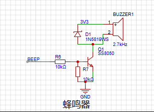
The buzzer
is used for various alarms and requires frequency matching.
The button circuit
is used for interaction and input .

The LED circuit
is pulled up to 3.3V and connected in series with a current-limiting resistor. It is used for prompts or warnings.

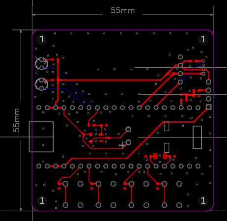
The PCB design
uses LCSC EDA.
It is a two-layer board, FR-4 material, 1.6mm thick. Dimensions: 55X55mm.
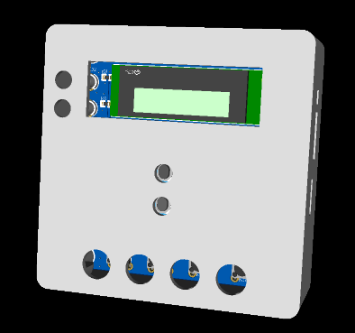
The 3D shell B design
also uses LCSC EDA,
as shown below .
The program design
uses VS Code + ESP32-IDF. Learn by following LCSC ESP32 development.
The following explains each driver.
The OLED driver
header file is shown below. Here, IIC simulation is used.
#ifndef __OLED_H
#define __OLED_H
#include "stdlib.h"
// // 1: Use software IIC
// // 0: Use hardware IIC
// #define USE_SOFT_HARD 1
#ifndef u8
#define u8 __uint8_t
#endif #ifndef
u16 #define
u16 __uint16_t
#endif
#ifndef u32
#define u32 __uint32_t
#endif
//-----------------OLED port porting----------------
#define OLED_SCL_PIN 7
#define OLED_SDA_PIN 6
//-----------------OLED port definition----------------
#define OLED_SCL_Clr() gpio_set_level(OLED_SCL_PIN, 0)//SCL
#define OLED_SCL_Set() gpio_set_level(OLED_SCL_PIN, 1)
#define OLED_SDA_Clr() gpio_set_level(OLED_SDA_PIN, 0)//SDA
#define OLED_SDA_Set() gpio_set_level(OLED_SDA_PIN, 1)
#define OLED_CMD 0 //Write command
#define OLED_DATA 1 //Write data
//Delay ms level
void delay_ms(int ms);
void OLED_ClearPoint(u8 x,u8 y);
void OLED_ColorTurn(u8 i);
void OLED_DisplayTurn(u8 i);
void I2C_Start(void);
void I2C_Stop(void);
void void OLED_DisPlay_On(void);
void OLED_DisPlay_Off
(
void
); void
OLED_Refresh ( void); void OLED_Clear(void); void OLED_DrawPoint(u8 x,u8 y,u8 t); void OLED_DrawLine(u8 x1,u8 y1,u8 x2,u8 y2,u8 mode); void OLED_DrawCircle(u8 x,u8 y,u8 r); void OLED_ShowChar(u8 x,u8 y,u8 chr,u8 size1,u8 mode); void OLED_ShowChar6x8(u8 x,u8 y,u8 chr,u8 mode); void OLED_ShowString(u8 x,u8 y,u8 *chr,u8 size1,u8 mode); void OLED_ShowNum(u8 x,u8 y,u32 num,u8 len,u8 size1,u8 mode); void OLED_ShowChinese(u8 x,u8 y,u8 num,u8 size1,u8 mode); void OLED_ScrollDisplay(u8 num,u8 space,u8 mode); void OLED_ShowPicture(u8 x,u8 y,u8 sizex,u8 sizey,u8 BMP[],u8 mode); void OLED_Init(void); #endif function implementation: #include "oled.h" #include #include #include #include "driver/gpio.h" #include "oledfont.h" #include "esp_timer.h" #include "driver/gpio.h" #include "esp_rom_sys.h" #include "freertos/FreeRTOS.h" #include "freertos/task.h" #include "driver/i2c.h" u8 OLED_GRAM[144][8]; //Delay us level void IIC_delay(void) { esp_rom_delay_us(5); } //Delay ms level void delay_ms(int ms) { vTaskDelay(ms / portTICK_PERIOD_MS); } // Invert display function void OLED_ColorTurn(u8 i) { if(i==0) { OLED_WR_Byte(0xA6,OLED_CMD);//Normal display } if(i==1) { OLED_WR_Byte(0xA7,OLED_CMD);//Inverted color display } } // Rotate screen 180 degrees void OLED_DisplayTurn(u8 i) { if(i==0) { OLED_WR_Byte(0xC8,OLED_CMD);//Normal display OLED_WR_Byte(0xA1,OLED_CMD); } if(i==1) { OLED_WR_Byte(0xC0,OLED_CMD);//Inverted display OLED_WR_Byte(0xA0,OLED_CMD); } } // Start signal void I2C_Start(void) { gpio_set_direction(OLED_SDA_PIN, GPIO_MODE_OUTPUT); // Configure the pin as output mode
OLED_SDA_Set();
OLED_SCL_Set();
IIC_delay();
OLED_SDA_Clr();
IIC_delay();
OLED_SCL_Clr();
IIC_delay();
}
// End signal
void I2C_Stop(void)
{
gpio_set_direction(OLED_SDA_PIN, GPIO_MODE_OUTPUT); // Configure pin as output mode
OLED_SDA_Clr();
OLED_SCL_Set();
IIC_delay();
OLED_SDA_Set();
}
// Wait for signal response
u8 I2C_WaitAck(void) // Measure data signal level
{
u8 ucErrTime=0;
gpio_set_direction(OLED_SDA_PIN, GPIO_MODE_INPUT); // Configure pin as input mode
OLED_SDA_Set();
IIC_delay();
OLED_SCL_Set();
IIC_delay();
while(gpio_get_level(OLED_SDA_PIN))
{
ucErrTime++;
if(ucErrTime>250)
{
I2C_Stop();
return 1;
}
}
OLED_SCL_Clr();
IIC_delay();
return 0;
}
// Write one byte
void Send_Byte(u8 dat)
{
u8 i;
gpio_set_direction(OLED_SDA_PIN, GPIO_MODE_OUTPUT); // Configure the pin to output mode
for(i=0;i<8;i++)
{
if(dat&0x80)// Write the 8 bits of dat from the most significant bit to the least significant bit
{
OLED_SDA_Set();
}
else
{
OLED_SDA_Clr();
}
IIC_delay();
OLED_SCL_Set();
IIC_delay();
OLED_SCL_Clr();// Set the clock signal low
dat<<=1;
}
}
void I2C_Ack(void)
{
OLED_SCL_Clr();
gpio_set_direction(OLED_SDA_PIN, GPIO_MODE_OUTPUT); // Configure the pin as output mode
OLED_SDA_Clr();
IIC_delay();
OLED_SCL_Set();
IIC_delay();
OLED_SCL_Clr();
}
void I2C_NAck(void)
{
OLED_SCL_Clr();
gpio_set_direction(OLED_SDA_PIN, GPIO_MODE_OUTPUT); // Configure the pin as output mode
OLED_SDA_Set();
IIC_delay();
OLED_SCL_Set();
IIC_delay();
OLED_SCL_Clr();
}
u8 Read_Byte(void)
{
u8 i,receive=0;
gpio_set_direction(OLED_SDA_PIN, GPIO_MODE_INPUT); // Configure pin to input mode
for(i=0;i<8;i++ )
{
OLED_SCL_Clr();
IIC_delay();
receive<<=1;
OLED_SCL_Set();
if(gpio_get_level(OLED_SDA_PIN))
receive++;
IIC_delay();
}
return receive;
}
// Send a byte
// mode: data/command flag 0, indicates command; 1, indicates data;
void OLED_WR_Byte(u8 dat,u8 mode)
{
I2C_Start();
Send_Byte(0x78);
I2C_WaitAck();
if(mode){Send_Byte(0x40);}
else{Send_Byte(0x00);}
I2C_WaitAck();
Send_Byte(dat);
I2C_WaitAck();
I2C_Stop();
}
// Enable OLED display
void OLED_DisPlay_On(void)
{
OLED_WR_Byte(0x8D,OLED_CMD);// Enable charge pump
OLED_WR_Byte(0x14,OLED_CMD);// Enable charge pump
OLED_WR_Byte(0xAF,OLED_CMD);// Turn on screen
}
// Disable OLED display
void OLED_Display_Off(void)
{
OLED_WR_Byte(0x8D,OLED_CMD);// Enable charge pump
OLED_WR_Byte(0x10,OLED_CMD);// Disable charge pump
OLED_WR_Byte(0xAE,OLED_CMD);// Turn off screen
}
// Update video memory to OLED
void OLED_Refresh(void)
{
u8 i,n;
for(i=0;i<8;i++)
{
OLED_WR_Byte(0xb0+i,OLED_CMD); // Set row start address
OLED_WR_Byte(0x00,OLED_CMD); // Set low column start address
OLED_WR_Byte(0x10,OLED_CMD); // Set high column start address
I2C_Start();
Send_Byte(0x78);
I2C_WaitAck();
Send_Byte(0x40);
I2C_WaitAck();
for(n=0;n<128;n++)
{
Send_Byte(OLED_GRAM[n][i]);
I2C_WaitAck();
}
I2C_Stop();
}
}
// Clear screen function
void OLED_Clear(void)
{
u8 i,n;
for(i=0;i<4;i++)
{
for(n=0;n<128;n++)
{
OLED_GRAM[n][i]=0;//Clear all data
}
}
//OLED_Refresh();//Update display
}
// Draw point
//x:0~127
//y:0~63
//t:1 Fill with 0, clear
void OLED_DrawPoint(u8 x,u8 y,u8 t)
{
u8 i,m,n;
i=y/8;
m=y%8;
n=1<0)incx=1; // Set single step direction
else if (delta_x==0)incx=0;//Vertical line
else {incx=-1;delta_x=-delta_x;}
if(delta_y>0)incy=1;
else if (delta_y==0)incy=0;//Horizontal line
else {incy=-1;delta_y=-delta_x;}
if(delta_x>delta_y)distance=delta_x; //Select the basic incremental coordinate axis
else distance=delta_y;
for(t=0;tdistance)
{
xerr-=distance;
uRow+=incx;
}
if(yerr>distance)
{
yerr-=distance;
uCol+=incy;
}
}
}
//x,y: circle center coordinates
//r: radius of circle
void OLED_DrawCircle(u8 x,u8 y,u8 r)
{
int a, b,num;
a = 0;
b = r;
while(2 * b * b >= r * r)
{
OLED_DrawPoint(x + a, y - b,1);
OLED_DrawPoint(x - a, y - b,1);
OLED_DrawPoint(x - a, y + b,1);
OLED_DrawPoint(x + a, y + b,1);
OLED_DrawPoint(x + b, y + a,1);
OLED_DrawPoint(x + b, y - a,1);
OLED_DrawPoint(x - b, y - a,1);
OLED_DrawPoint(x - b, y + a,1);
a++;
num = (a * a + b * b) - r*r; // Calculate the distance of the drawn point from the center of the circle
if (num > 0)
{
b--;
a--;
}
}
}
// Display a character at a specified position, including part of the character
// x: 0~127
// y: 0~63
// size1: Select font 6x8/6x12/8x16/12x24
// mode: 0, inverted color display; 1, normal display
void OLED_ShowChar(u8 x,u8 y,u8 chr,u8 size1,u8 mode)
{
u8 i,m,temp,size2,chr1;
u8 x0=x,y0=y;
if(size1==8)size2=6;
else size2=(size1/8+((size1%8)?1:0))*(size1/2); // Get the number of bytes occupied by the dot matrix set corresponding to a character in the font
chr1=chr-' '; // Calculate the offset value
for (i = 0; i >= 1;
y++;
}
x++;
if ((size1 != 8) && ((x - x0) == size1/2))
{x = x0; y0 = y0 + 8;}
y = y0;
}
}
// Display string
//x, y: starting coordinates
//size1: font size
//*chr: string starting address
//mode: 0, inverted color display; 1, normal display
void OLED_ShowString(u8 x, u8 y, u8 *chr, u8 size1, u8 mode)
{
while ((*chr >= ' ') && (*chr <= '~')) // Check if it is an illegal character!
{
OLED_ShowChar(x, y, *chr, size1, mode);
if (size1 == 8) x += 6;
else x += size1/2;
chr++;
}
}
//m^n
u32 OLED_Pow(u8 m,u8 n)
{
u32 result=1;
while(n--)
{
result*=m;
}
return result;
}
// Display number
//x,y : starting coordinates
//num : number to display
//len : number of digits
//size : font size
//mode : 0, inverted color display; 1, normal display
void OLED_ShowNum(u8 x,u8 y,u32 num,u8 len,u8 size1,u8 mode)
{
u8 t,temp,m=0;
if(size1==8)m=2;
for(t=0;t>=1;
y++;
}
x++;
if((x-x0)==size1)
{x=x0;y0=y0+8;}
y=y0;
}
}
//num The number of Chinese characters to display
//space The interval between each display
//mode:0, inverted color display;1, normal display
void OLED_ScrollDisplay(u8 num,u8 space,u8 mode)
{
u8 i,n,t=0,m=0,r;
while(1)
{
if(m==0)
{
OLED_ShowChinese(128,24,t,16,mode); //Write a Chinese character and store it in the OLED_GRAM[][] array
t++;
}
if(t==num)
{
for(r=0;r<16*space;r++) //Display interval
{
for(i=1;i<144;i++)
{
for(n=0;n<8;n++)
{
OLED_GRAM[i-1][n]=OLED_GRAM[i][n];
}
}
OLED_Refresh();
}
t=0;
}
m++;
if(m==16){m=0;}
for(i=1;i<144;i++) // Implement left shift
{
for(n=0;n<8;n++)
{
OLED_GRAM[i-1][n]=OLED_GRAM[i][n];
}
}
OLED_Refresh();
}
}
//x,y: starting coordinates
//sizex,sizey, image width and height
//BMP[]: array of images to be written
//mode:0, inverted color display;1, normal display
void OLED_ShowPicture(u8 x,u8 y,u8 sizex,u8 sizey,u8 BMP[],u8 mode)
{
u16 j=0;
u8 i,n,temp,m;
u8 x0=x,y0=y;
sizey=sizey/8+((sizey%8)?1:0);
for(n=0;n>=1;
y++;
}
x++;
if((x-x0)==sizex)
{
x=x0;
y0=y0+8;
}
y=y0;
}
}
}
// OLED initialization
void OLED_Init(void)
{
gpio_set_direction(OLED_SCL_PIN, GPIO_MODE_OUTPUT); // Configure pin as output mode
gpio_set_direction(OLED_SDA_PIN, GPIO_MODE_OUTPUT); // Configure pin as output mode
gpio_set_pull_mode(OLED_SDA_PIN,GPIO_PULLUP_ENABLE);
gpio_set_pull_mode(OLED_SCL_PIN,GPIO_PULLUP_ENABLE);
OLED_SCL_Clr();
OLED_SDA_Clr();
// OLED_RES_Clr();
delay_ms(200);
// OLED_RES_Set();
OLED_WR_Byte(0xAE,OLED_CMD); /*display off*/
OLED_WR_Byte(0x00,OLED_CMD); /*set lower column address*/
OLED_WR_Byte(0x10,OLED_CMD); /*set higher column address*/
OLED_WR_Byte(0x00,OLED_CMD); /*set display start line*/
OLED_WR_Byte(0xB0,OLED_CMD); /*set page address*/
OLED_WR_Byte(0x81,OLED_CMD); /*contract control*/
OLED_WR_Byte(0xff,OLED_CMD); /*128*/
OLED_WR_Byte(0xA1,OLED_CMD); /*set segment remap*/
OLED_WR_Byte(0xA6,OLED_CMD); /*normal / reverse*/
OLED_WR_Byte(0xA8,OLED_CMD); /*multiplex ratio*/
OLED_WR_Byte(0x1F,OLED_CMD); /*duty = 1/32*/
OLED_WR_Byte(0xC8,OLED_CMD); /*Com scan direction*/
OLED_WR_Byte(0xD3,OLED_CMD); /*set display offset*/
OLED_WR_Byte(0x00,OLED_CMD);
OLED_WR_Byte(0xD5,OLED_CMD); /*set osc division*/
OLED_WR_Byte(0x80,OLED_CMD);
OLED_WR_Byte(0xD9,OLED_CMD); /*set pre-charge period*/
OLED_WR_Byte(0x1f,OLED_CMD);
OLED_WR_Byte(0xDA,OLED_CMD); /*set COM pins*/
OLED_WR_Byte(0x00,OLED_CMD);
OLED_WR_Byte(0xdb,OLED_CMD); /*set vcomh*/
OLED_WR_Byte(0x40,OLED_CMD);
OLED_WR_Byte(0x8d,OLED_CMD); /*set charge pump enable*/
OLED_WR_Byte(0x14,OLED_CMD);
OLED_Clear();
OLED_WR_Byte(0xAF,OLED_CMD); /*display ON*/
} The
sht40 driver
header file is shown below. Here, IIC simulation is used, sharing pins with the OLED.
#ifndef __SHT40_H
#define __SHT40_H
#include "oled.h"
// Define SHT40 I2C address AD1B
#define SHT40_Write (0x44<<1) // Write address
#define SHT40_Read ((0x44<<1)+1) // Read address
// #define SHT40_Write (0x46<<1) // Write address
// #define SHT40_Read ((0x46<<1)+1) // Read address
u8 SHT40_Cal(void); //
double SHT40_GetTEM(void); //
double SHT40_GetHUM(void); //
#endif
The specific implementation functions are as follows:
#include "SHT40.h"
u8 writeData[1] = {0xFD};
u8 readData[6] = {0};
u16 Temp = 0,Humi = 0;
double Temperature = 0;
double Humidity = 0;
u8 SHT40_Cal(void)
{
I2C_Start();
Send_Byte(SHT40_Write);
if(I2C_WaitAck())
{
I2C_Stop();
return 1;
}
Send_Byte(0xFD);
if(I2C_WaitAck())
{
I2C_Stop();
return 2;
}
I2C_Stop();
delay_ms(10);
I2C_Start();
Send_Byte(SHT40_Read);
if(I2C_WaitAck())
{
I2C_Stop();
return 3;
}
for(u8 i=0;i<5;i++)
{
readData[i]=Read_Byte();
I2C_Ack();
}
readData[5]=Read_Byte();
I2C_NAck();
I2C_Stop();
Temperature = (1.0 * 175 * (readData[0] * 256 + readData[1])) / 65535.0 - 45;
Humidity = (1.0 * 125 * (readData[3] * 256 + readData[4])) / 65535.0 - 6.0;
if(Humidity<0)
Humidity=0;
if(Humidity>100)
Humidity=100;
return 0;
}
double SHT40_GetTEM(void)
{
return Temperature;
}
double SHT40_GetHUM(void)
{
return Humidity;
}
The buzzer driver
implementation function is as follows:
#include "bsp_pwm.h"
/**
* @Function description LEDC function initialization
* @Pass-in parameters none
* @Function return none
* @Note: The higher the PWM frequency, the lower the available duty cycle resolution.
*/
void LedcInitConfig(void)
{
// Prepare and apply the led PWM timer configuration
ledc_timer_config_t ledc_timer = {
.speed_mode = LEDC_MODE, // LED mode low speed mode.timer_num
= LEDC_TIMER, // Timer source for the channel, timer 0.duty_resolution
= LEDC_DUTY_RES, // Set the duty cycle resolution to 13 bits.freq_hz
= LEDC_FREQUENCY, // Set the output frequency to 5 kHz.clk_cfg
= LEDC_AUTO_CLK // Set the clock source for LED PWM to automatic
// LEDC_AUTO_CLK = When starting the timer, the LED source clock will be automatically selected according to the given resolution and duty cycle parameters.
};
ledc_timer_config(&ledc_timer);
// Prepare and apply the LEDC PWM channel configuration
ledc_channel_config_t ledc_channel = {
.speed_mode = LEDC_MODE, // LED mode low speed mode
. channel = LEDC_CHANNEL, // Channel 0.
timer_sel = LEDC_TIMER, // Timer source timer 0.
intr_type = LEDC_INTR_DISABLE, // Disable interrupts.
gpio_num = LEDC_OUTPUT_IO, // Output pin GPIO5
. duty = 0, // Set duty cycle to 0.
hpoint = 0
};
ledc_channel_config(&ledc_channel);
}
The header file is as follows:
#ifndef _BSP_PWM_H_
#define _BSP_PWM_H_
#include "driver/ledc.h"
#define LEDC_TIMER LEDC_TIMER_0 // Timer 0
#define LEDC_MODE LEDC_LOW_SPEED_MODE // Low speed mode
#define LEDC_OUTPUT_IO (12) // Define output GPIO as GPIO48
#define LEDC_CHANNEL LEDC_CHANNEL_0 // Use LEDC channel 0
#define LEDC_DUTY_RES LEDC_TIMER_13_BIT // Set LEDC resolution to 13 bits
#define LEDC_DUTY (4095) // Set duty cycle to 50%. ((2^13) - 1) * 50% = 4095
#define LEDC_FREQUENCY (100) //
/**
* @Function description LEDC function initialization
* @None input parameters
* @None function return value
* @Note: The higher the PWM frequency, the lower the available duty cycle resolution.
*/
void LedcInitConfig(void);
#endif
Key driver
header file:
#ifndef _BSP_KEY_H_
#define _BSP_KEY_H_
#include "driver/gpio.h"
#include "freertos/FreeRTOS.h"
#include "freertos/task.h"
//Set the button pins
#define KEY2_PIN 47
#define KEY3_PIN 18
#define KEY4_PIN 17
/**
* @Function description: Button pin initialization
* @Passed parameters
* @Function return
*/
void KeyGpioConfig(void);
/**
* @Function description: Get the level state on the button pin
* @Passed parameters: None
* @Function return: 0 = Button is pressed 1 = Button is not pressed
*/
uint8_t GetKeyValue(void);
#endif
Function implementation:
#include "bsp_key.h"
//Configure pin registers
//#define GPIO_INPUT_PIN_SEL (1ULL<


 京公网安备 11010802033920号

 1780400000


