Design Background:
ADCs (Analog-to-Digital Converters) are indispensable key components in electronic systems. They convert continuous analog signals into digital signals, enabling digital processing and analysis. ADCs play a crucial role in signal conversion, measurement and data acquisition, control system input, and communication and signal processing. Their widespread application promotes the intelligent and precise control of electronic equipment across various industries, and is one of the key factors driving modern technological progress.
Digital voltmeters and ammeters combine ADC technology with circuit measurement principles, accurately converting analog voltage and current signals into digital displays for easy reading and analysis by electronic engineers. This device not only improves the accuracy and efficiency of circuit measurements but also helps engineers better understand circuit behavior, serving as a powerful tool for electronic design and troubleshooting, and playing a vital supporting role in the work of electronic engineers. In product applications, digital voltmeters ensure the accuracy and safety of circuit design, while also providing strong support for product quality control and subsequent maintenance.
For the hardware design of
the step-down module, the LDO selection is as follows:
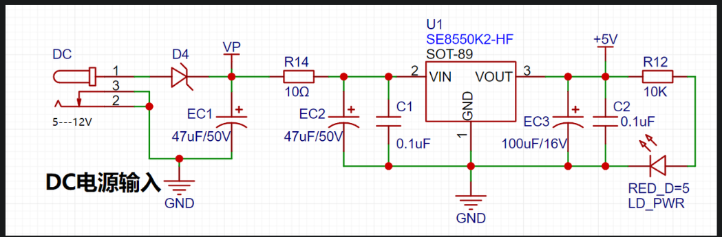
This project uses an LDO as the power supply. Considering that most voltmeter products are used in industrial scenarios with 24V or 36V power supplies, the SE8550K2 with a maximum input voltage of up to 40V was chosen. The main reason for not using a DC-DC step-down circuit to handle large voltage drops is to avoid introducing DC-DC ripple interference during the design process; a secondary reason is to reduce project costs. For
the MCU selection
, to reduce the learning curve, this project uses the LCSC CW32F030C8Tx development board (core board) as the main controller. However, this does not mean we will discuss this section less. From the perspective of training engineers, the correct selection of the main controller is crucial, as it relates to the overall advantage of the project.
Regarding the voltmeter and current meter, some debugging and testing were performed using STM32/CW32 and some other 32-bit microcontrollers. Here, only a comparison with the STM32F103C8T6 is made as a reference for learning device selection, mainly to provide ideas and improve understanding.
Avoid blindly selecting
an MCU (Microcontroller Unit). When selecting an MCU for this project, multiple aspects need to be considered to ensure that the chosen MCU meets the project requirements.
Clearly define your project needs: Understand the required computing power, including clock speed, processor core type, and whether a floating-point unit is needed.
Identify the required I/O ports and important peripherals, such as ADC peripherals. Since this is a development board project, primarily for debugging and learning, there are no strict limitations on the number of I/O ports; i.e., the associated costs are not considered.
Key advantages of CW32 in this project
: Wide operating temperature range: -40~105℃;
Wide operating voltage range: 1.65V~5.5V (STM32 only supports 3.3V systems)
; Strong anti-interference: HBM ESD 8KV; All ESD reliability reaches the highest international standard level (STM32 ESD 2KV);
Project focus - Better ADC: 12-bit high-speed ADC, achieving ±1.0LSB INL 11.3ENOB; Multiple Vref reference voltages... (STM32 only supports VDD=Vref);
Stable and reliable eFLASH technology.
Key features of CW32's ADC;
Key focus in this project: 4-channel reference voltage source.
Precautions:
Some problems were encountered when replicating this project.
1. The TL431 component was purchased incorrectly; it was intended to be a through-hole component, but due to not checking the package, it was purchased as a surface-mount component.
2. During the process of learning and using CW32, I encountered some issues related to using chips I was unfamiliar with. Previously, I had only worked with STM32 chips, which could be configured using CubumX (and I also learned the standard library). CW32 uses a standard porting library, which differs somewhat from the STM32 standard library.
The demo video is attached as
Attachment 3.
Other attachments
include: Attachment 1 is the BOM list, Attachment 2 is the project code, and Attachment 3 is the demo video.


 京公网安备 11010802033920号

 1N4112D-1TRE3


