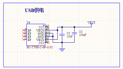
 USB power supply interface Lithium battery charging circuit
  The power supply switching circuit
  Charging
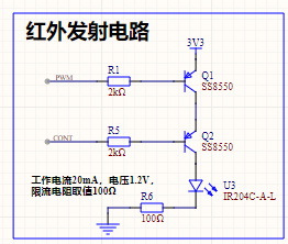
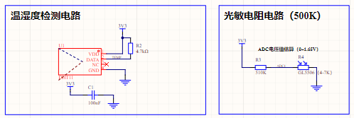
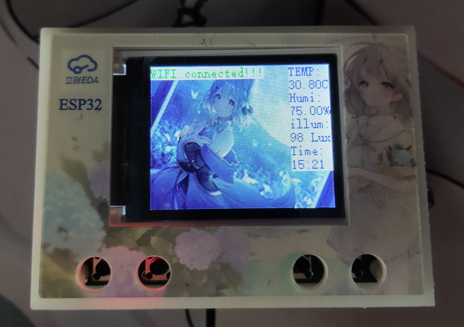
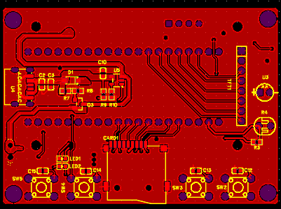
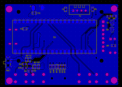
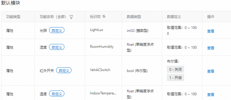
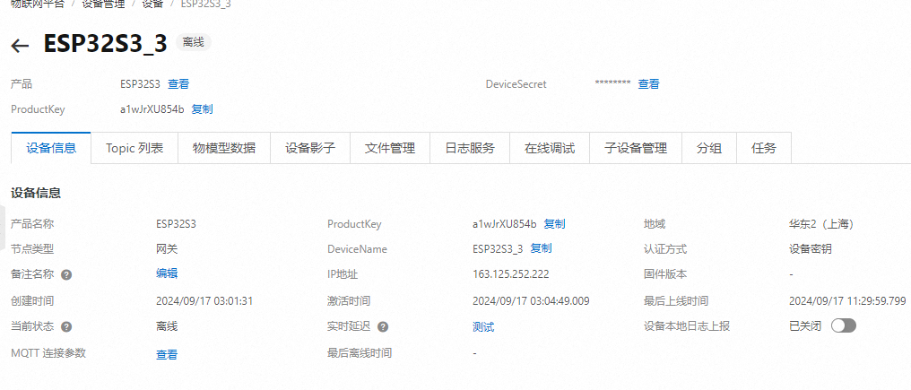
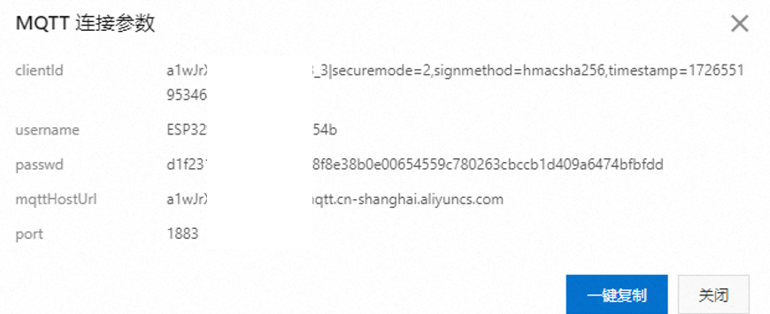
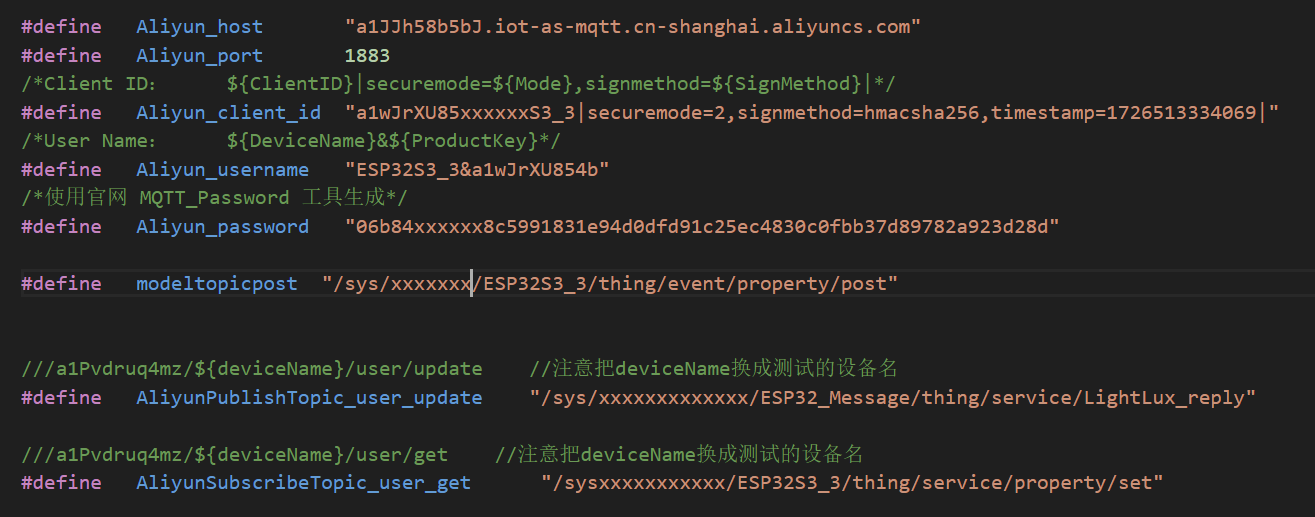
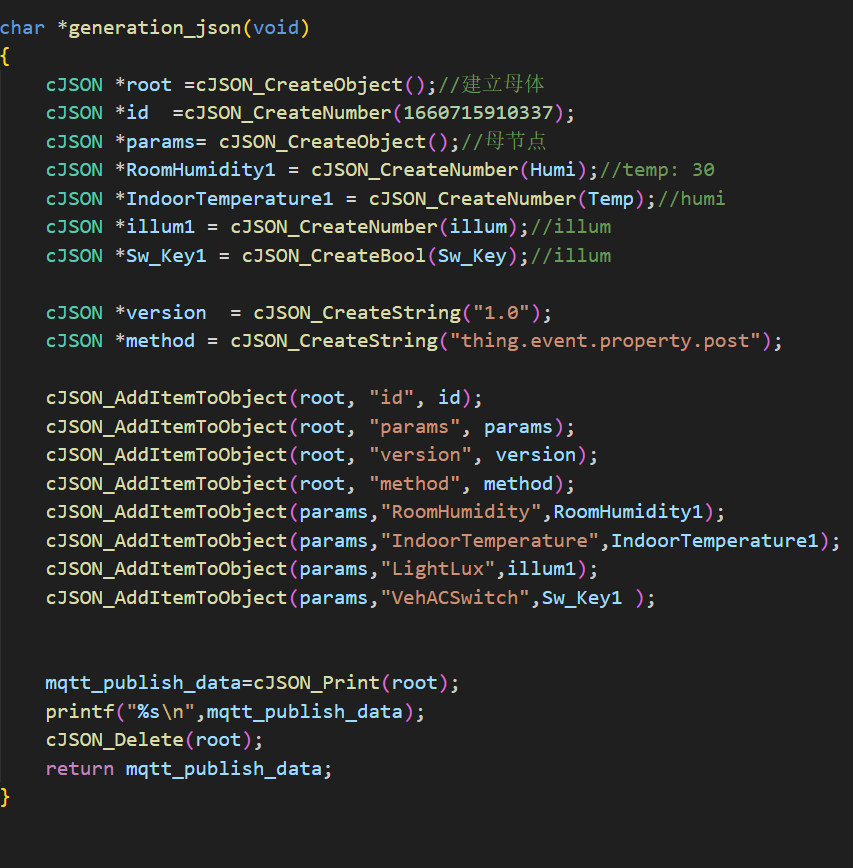
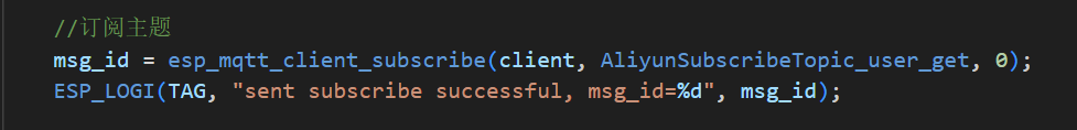
 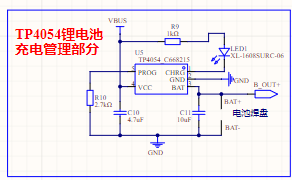 Circuit: The display circuit uses a 1.8-inch OLED screen. This screen uses an SPI interface for communication, resulting in a stable refresh rate and good display quality. 2.6 Infrared Transmitting Circuit: According to the Espressif official manual, the ESP32S3 has infrared functionality and can transmit infrared signals through configuration functions. However, after verification, the transmitted infrared signal is only 32 bits (refer to the Espressif official API for details). However, actual measurements showed that the air conditioner remote control sends signals of over 100 bits at a time. Therefore, after multiple attempts, this solution was abandoned. Therefore, the infrared emitting circuit in this project uses a timer to output a 38kHz PWM waveform to simulate the infrared NEC protocol. The circuit is controlled by two I/O ports: one for enabling the signal and the other for transmitting the signal. All I/O ports are controlled by PNP transistors to turn on and off, and the NEC protocol is simulated through encoding. 2.7 Temperature, Humidity, and Light Detection Circuit : The temperature and humidity sensor uses the cost-effective DHT11, costing less than two yuan per sensor. Light detection uses a photoresistor voltage divider, and then the voltage is read and converted by an ADC. 3. Physical Image of the Temperature, Humidity, and Light Detection Circuit : [Image of the physical product and its display on the cloud smart APP] 4. PCB Design Notes: In the PCB design, the power supply traces should be thickened, and copper pours should be used for connections when necessary. 5. Key Program Descriptions 5.1 The Alibaba Cloud platform access project uses the MQTT protocol to connect to Alibaba Cloud. Before writing the program, you need to register an account on the Alibaba Cloud IoT platform, create products and devices, and define product functions: Alibaba Cloud Platform Product Creation Alibaba Cloud Platform Function Definition Alibaba Cloud Platform Device Creation After the device is created, we can obtain the MQTT connection parameters and the Topic list used for attribute subscription and publication: MQTT Connection Parameters Topic List Write the above information into the code as follows: After writing the information into the code , connect to WIFI and use the mqtt_app_start() function to initialize and connect the device to Alibaba Cloud. 5.2 Alibaba Cloud Message Subscription and Publication After writing the Topic list into the program as described in 5.1, we can create messages using cJSON and then call the esp_mqtt_client_publish function to publish the message:
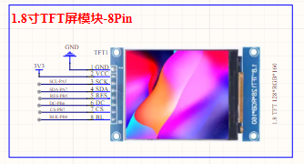


 Logic "0": 560µs effective pulse + 560µs idle interval, total duration 1.12ms. Logic "1": 560µs effective pulse + 1.68ms idle interval, total duration 2.24ms (twice that of Logic 0).
  The start flag sequence for each frame is: a 9ms AGC pulse (16 times the 560µs pulse used for logic data bits) + 4.5ms idle.

 The image above shows the infrared receiver output waveform tested with an oscilloscope when the air conditioner is turned on. The power-on code information can be obtained through protocol analysis.
All reference designs on this site are sourced from major semiconductor manufacturers or collected online for learning and research. The copyright belongs to the semiconductor manufacturer or the original author. If you believe that the reference design of this site infringes upon your relevant rights and interests, please send us a rights notice. As a neutral platform service provider, we will take measures to delete the relevant content in accordance with relevant laws after receiving the relevant notice from the rights holder. Please send relevant notifications to email: bbs_service@eeworld.com.cn.
It is your responsibility to test the circuit yourself and determine its suitability for you. EEWorld will not be liable for direct, indirect, special, incidental, consequential or punitive damages arising from any cause or anything connected to any reference design used.
Supported by EEWorld Datasheet
EEWorld
subscription
account

EEWorld
service
account

Automotive
development
community

Robot
development
community

About Us Customer Service Contact Information Datasheet Sitemap LatestNews


Room 1530, 15th Floor, Building B,
No.18 Zhongguancun Street,
Haidian District,
Beijing, Postal Code: 100190
China
Telephone: 008610 8235 0740
 京公网安备 11010802033920号

 HF9316-012L-34-I


