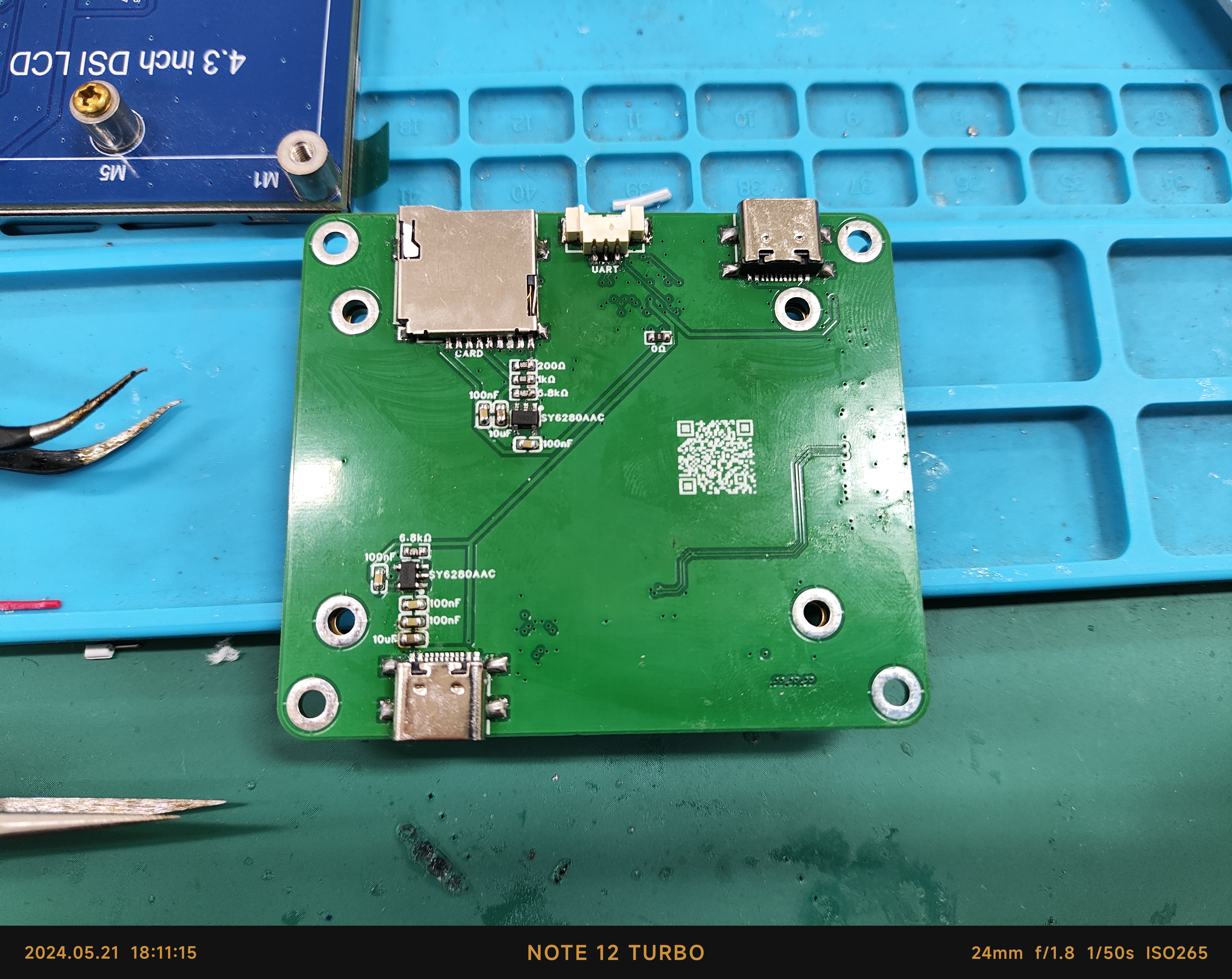
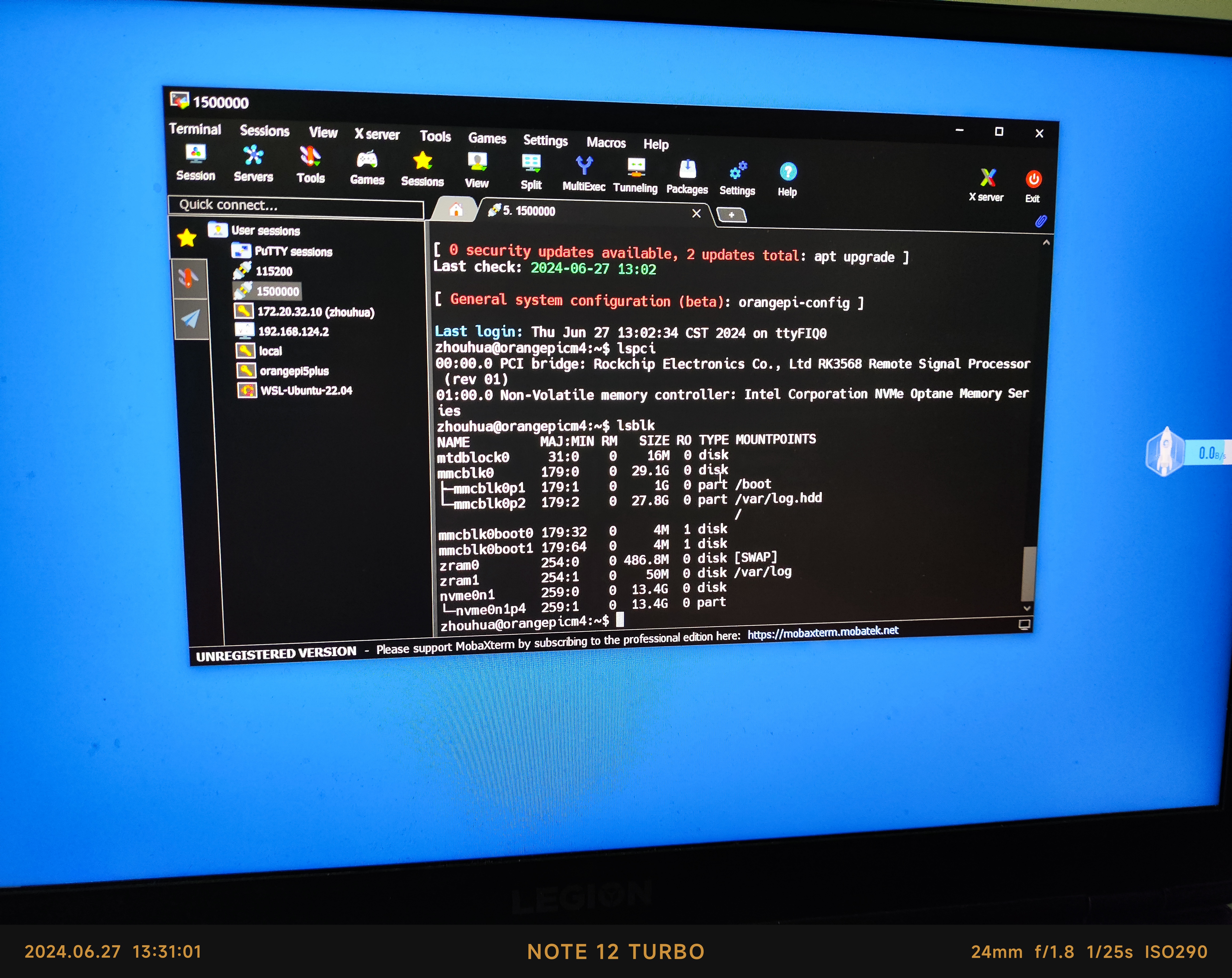
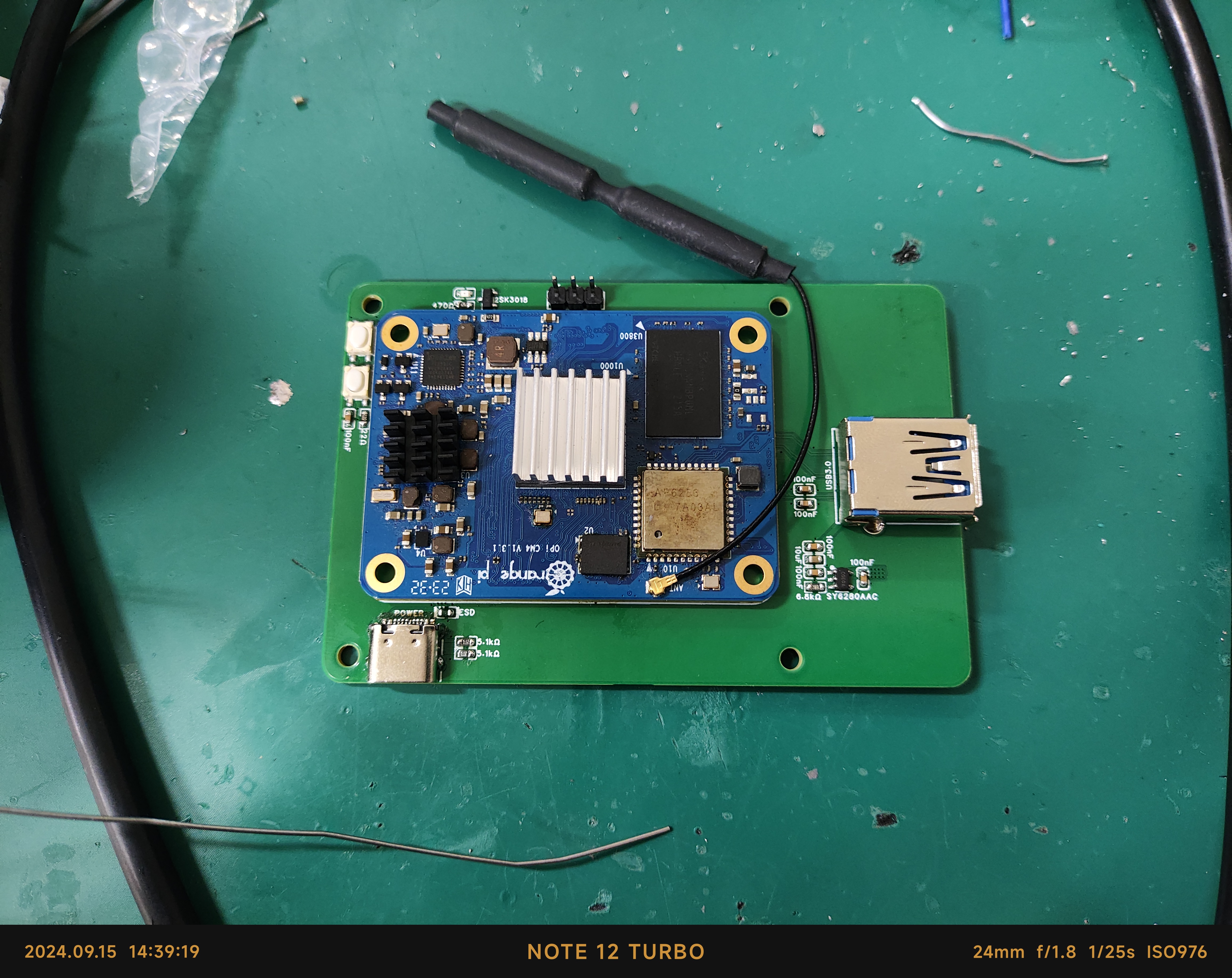
The Orange Pi CM4 baseboard, measuring only 65*56mm, is compatible with Raspberry Pi 4B mounting holes and can use MIPI screens compatible with Raspberry Pi 4B.
It features a Type-C power supply, memory card slot, USB 2.0 OTG, MIPI DSI, and Boot and Reset buttons. A debug serial port is provided via a 1.25mm 3-pin connector, and PCIe and Gigabit Ethernet ports are provided via an FPC 16-pin connector. The impedance is verified
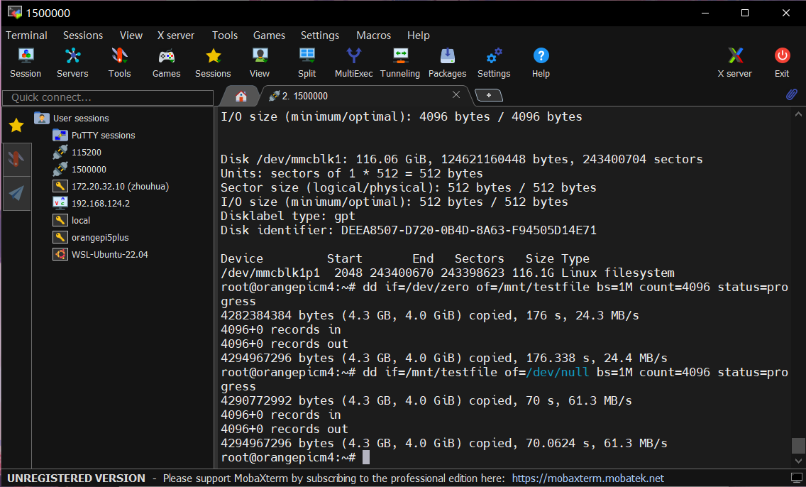
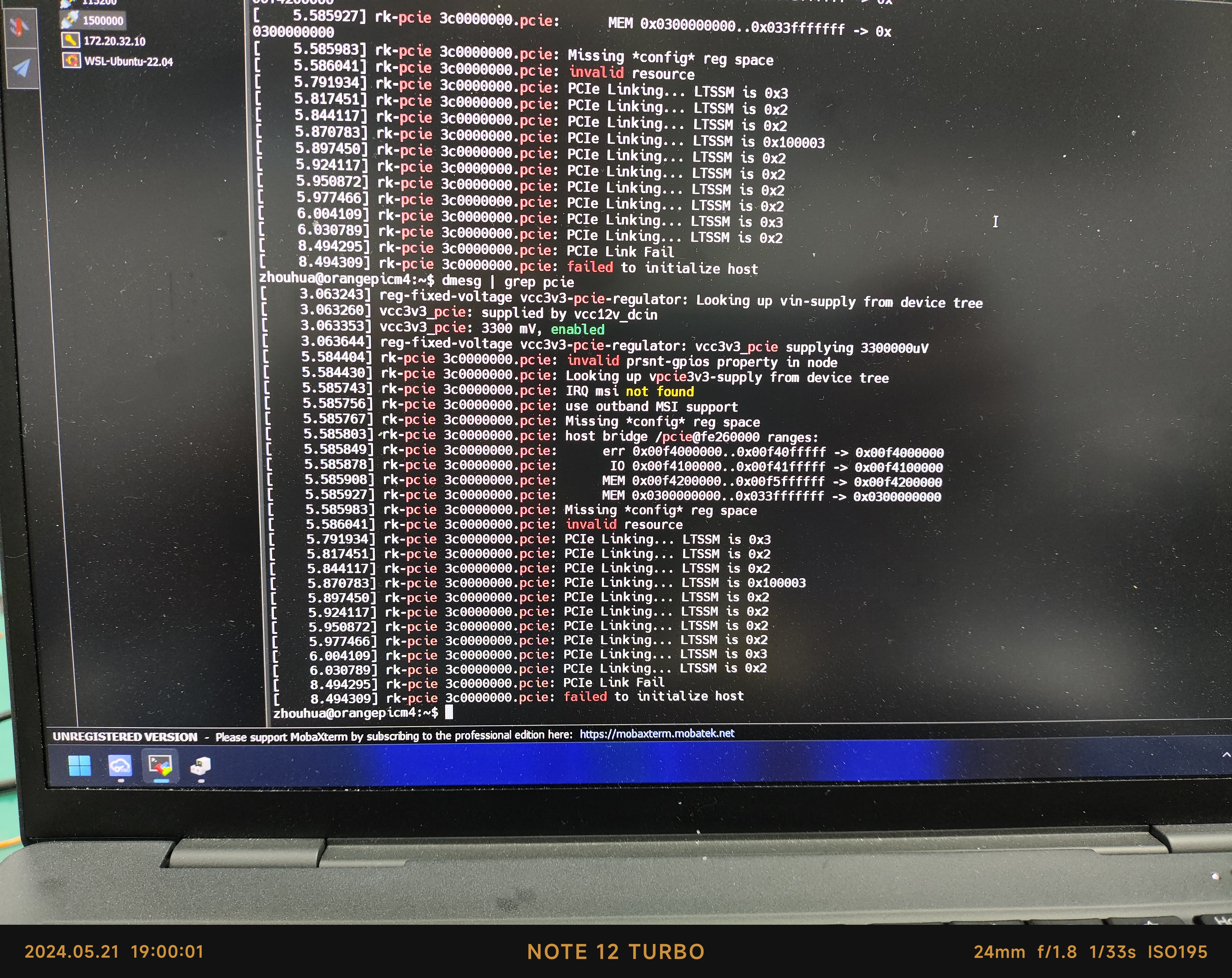
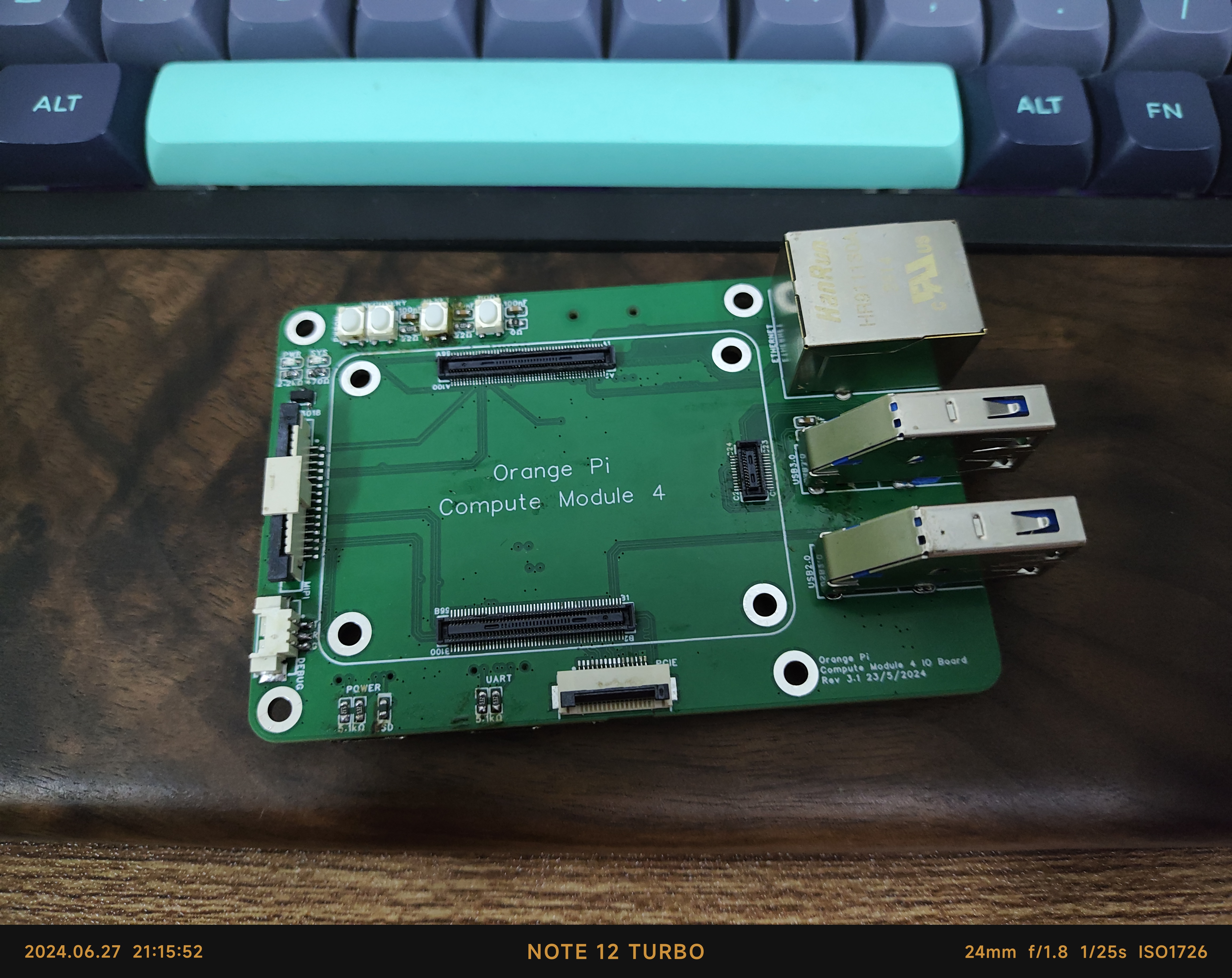
using JLC04161H-3313 : memory card and MIPI screen . Updated 2024.6.28: A new version has been designed, and the PCIe mini-board is complete. PCIe hard drives work normally on the new board. ![PCB] ![Front] ![Back] ![Memory Card Test] ~~About PCIe: The mini-board is complete, but there seems to be an impedance problem, resulting in the error: PCIe Link Fail~~Note: PCIe is definitely unusable!!! ![PCIe Small Board] ![Error Report] Updated 2024.6.28: ![1719580558235.jpg] PCIe is available on the new baseboard ![1719580558254.jpg] ![1719580558245.jpg] Updated 9.15: New version verified ![IMG_20240915_144022.jpg] ![IMG_20240915_143919.jpg]


VID_20240521_203621_1.mp4
PDF_Raspberry Pi Hole Spacing Orange Pie CM4 Base Plate.zip
Altium_Raspberry Pi Hole Spacing Orange Pie CM4 Base Plate.zip
PADS_Raspberry Pi Hole Spacing Orange Pie CM4 Base Plate.zip
BOM_Raspberry Pi Hole Spacing Orange Pie CM4 Baseplate.xlsx
92215
Carrier board based on Zhengdian M48Z M3
This document describes the STM32 carrier board used by the Magician team from ShanghaiTech University for their training and participation in the 2024 National Electronic Design Contest (NCDC) provincial competition's control problem. The project utilized the Zhengdian Atom M48Z STM32F103C8T6 carrier board, with basic peripherals brought out.
Video Link:
https://www.bilibili.com/video/BV1jb421e7V6/?spm_id_from=333.999.0.0&vd_source=0f4f047c9f645f8d80a94c78c947d2c7
This project is an STM32 carrier board designed by the Magician team at ShanghaiTech University for the 2024 National Electronic Design Contest (NCDC) control problem training and competition. After being fortunate enough to achieve first place in the NCDC control problem with two senior students in 2023, the Magician team began to be responsible for the training and preparation of control-related problems in the school's NCDC. To enable team members or other interested students to quickly get started with embedded tasks, and to ensure module reusability during the competition, this project uses the Zhengdian Atom M48Z STM32F103C8T6 minimum system board, and brings out the basic peripherals.
Because it was urgently needed for training, the preparation time was less than a week. Furthermore, the author's hardware engineering experience is relatively limited. Therefore, this project has some design flaws in certain aspects, which will be explained in detail later. Your understanding is appreciated!
Peripheral Interface:
This project is mainly based on the Zhengdian M48Z minimum system board, configuring and bringing out commonly used peripherals. These include 7 TIM channels, 1 CAN channel, 2 UART channels, 4 ADC channels, 1 I2C channel, 1 SPI channel, and several GPIO INPUT/OUTPUT.
Project Parameters
: 1. Regarding the power
input: It is a wide-range input of 12-24V with reverse connection protection and 2A current limiting (depending on the resettable fuse). The input is stepped down through an LM2596S-5.0 to power the servo motor and DC motor. Given the very low performance of the 2596 (nominal 3A), it may not be sufficient and has a large footprint. Future solutions plan to replace it with a TMI3351 or LM3150.
In addition, to ensure the normal power supply of the CAN transceiver and MCU, we used two wide-input LDOs, MD8350A and MD8333A. When purchasing materials, please pay attention to the model number containing "A" (as the pins differ depending on whether "A" is included, making a mistake will cause the chip to burn out).
It is worth noting that an oversight during the design resulted in the silkscreen markings for the 5V and GND of the DC motor power supply port being reversed; please correct this.
2. Regarding UART:
To adapt to the DBUS interface of the DR16 receiver, the board has a built-in BJT inverting circuit, and only Tx is brought out, providing 5V power. The other UART works normally.
3. Regarding the I2C1 and T3C2 conflict
: The I2C1 was brought out for possible functions such as reading and writing EEPROM, driving the LCD, or receiving I2C ranging feedback packets. After failing during testing, it was only through the errata manual that it was learned that the clock of T3C2 of the F103C8T6 conflicts with that of I2C1. Once I2C1 is EN, T3C2 will output a constant high level (this issue is quite coincidental). The T3C2 is used as the buzzer drive signal, and its DC output could cause it to burn out, so only one of the two can be selected. When this problem was discovered, the board had already been surface-mounted, so the only option was to temporarily disable I2C1 while retaining the normal buzzer function.
4. Regarding GPIO multiplexing:
Given the limited pin resources of the C8T6, the project used a 74HC238 decoder, but its effectiveness was limited. Surface mounting and pinouts can be adjusted as needed. In later versions, we replaced it with a 64-pin F412, making the related multiplexing unnecessary.
5. Regarding CAN:
To facilitate more precise and efficient control of brushless DC motors from companies like DJI or DM for experienced users, we have reserved five XT30 power supplies and GH1.25 * 2p pinouts on the board. The XT30 is directly connected to the power input; the GH1.25 uses DJI's CAN wiring sequence. If using motors from companies like DM, remember to swap the wiring sequence.
In summary and looking
ahead, due to various reasons, the board that should have been completed two months before the electronics competition has been delayed until now, and we sincerely apologize for that. There are also many shortcomings and areas for improvement in this project, and we hope to do better in the next iteration. The Magician team will also use the newly designed carrier board and minimum system board as much as possible in the 2025 season's intramural competition, providing a better hands-on experience for newcomers and laying the foundation for future self-made control boards that replace the C board. We will also open-source the relevant boards after verification, and welcome everyone's feedback. Thank you! Regarding
the software code,
since it is only a carrier board or power distribution board, only the CubeMX configuration file is provided here.
M48Zemptycode.ioc
PDF_Carrier Board Based on Zhengdian M48Z M3.zip
Altium_Carrier Board Based on Zhengdian M48Z M3.zip
PADS_Carrier Board Based on Zhengdian M48Z M3.zip
BOM_Based on Zhengdian M48Z M3 Carrier Board.xlsx
92216
World Blocks
A miniature world encased in a box, accessible via Wi-Fi from any device with a browser. Once accessed, you can explore this world! Multiplayer is also supported, and if the ESP32 C3 can connect to the public internet, remote multiplayer is even possible! Glimpses into the world through a "window."
Video Link:
World Box Introduction
Project Overview
A small world contained in a box, accessible via Wi-Fi from any device with a browser. Once accessed, you can explore the world! Multiplayer online play is also possible, and if the ESP32 C3 can connect to the public internet, remote multiplayer play is even possible! Glance into the world through a "window".
The project is simple to solder, the code is open source, and replication costs are low.
Project Functionality
A world contained in a box—perhaps with the development of AI it could truly become a real world, but not yet.
Project Parameters
Only SuperMINI ESP32 C3 is available.
Charging is done using a charging management IC; green and red lights illuminate during charging, and the red light turns off when fully charged.
A password is required to enter the world, but Wi-Fi itself is password-free.
Principle Analysis (Hardware Description)
This project uses the ESP32 C3 SuperMINI module as a network server, along with an SD card circuit for server storage, and a lithium battery management circuit for device charging and discharging management. The
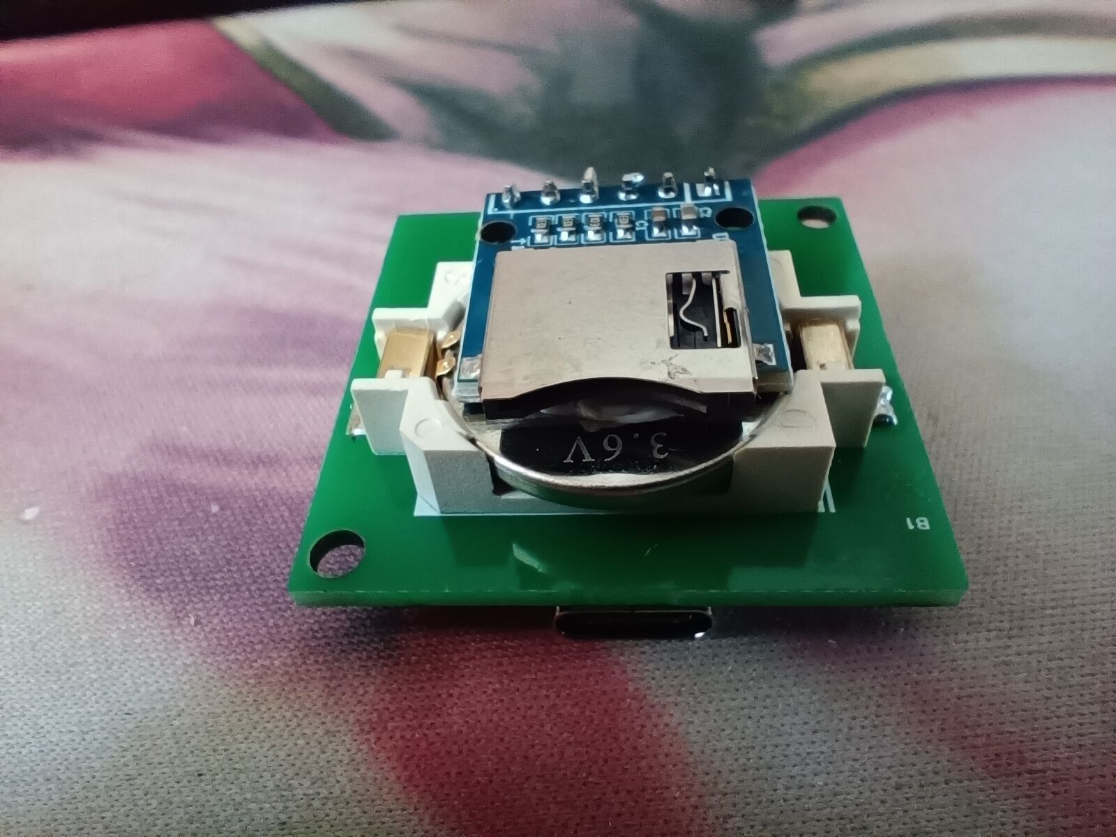
SD card circuit is electrically isolated from the battery below using soft adhesive, thus improving integration through 3D circuit construction.
Software Code
Any network server code can be used. A sandbox game was developed for the project. Below is a demonstration example:
**Important Notes :
** This section can be used to highlight key points or common mistakes during design and production. Example:
Always solder the switch last; otherwise, short circuits are likely.
Always solder the SD card module after installing the battery; otherwise, the battery cannot be installed. **
Assembly Process:
** The physical prototype
is not yet complete; the outer shell is a perfect cube.
World Box Introduction.mp4
web.ino
PDF_World Blocks.zip
Altium_WorldBlocks.zip
PADS_World Blocks.zip
BOM_WorldCubes.xlsx
92220
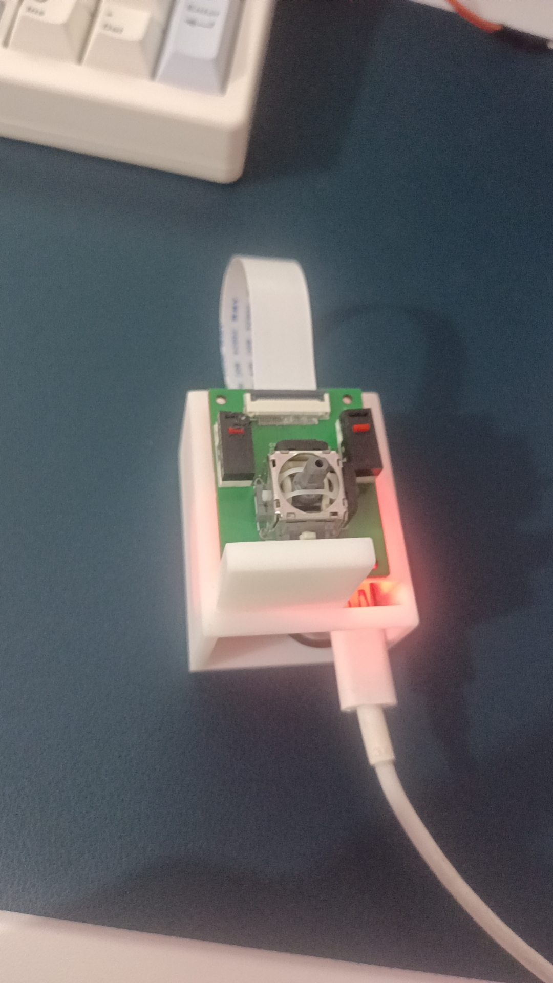
ESP32-based personalized posture mouse
This mouse integrates remote sensing, microswitches, and a gyroscope based on the ESP32 module, enabling personalized design.
Project Overview:
This project is a personalized mouse design based on the ESP32 module. It integrates an MPU6050 gyroscope, Bluetooth communication, a 2D joystick, and microswitches to achieve personalized mouse functions.
Project Functions:
This design is a personalized mouse based on the ESP32 module, featuring a Bluetooth module, two microswitches, a 2D joystick (including a remote sensing switch), and an MPU6050 for detecting angle movement.
Microswitches: Enable left and right mouse button functions
. 2D Joystick: Currently used only as a scroll wheel, but can be modified later based on functional requirements.
MPU6050: Enables angle detection, controlling the speed and direction of mouse movement based on the angle. Only two angle directions are used for control here, with one more angle application reserved.
Bluetooth Module: Interacts with the host computer via Bluetooth, transmitting collected mouse information.
Project Parameters:
The MPU6050 can measure angles in three directions, enabling directional mouse control beyond just left-hand movement.
The circuit switching is performed using a CJ3401, enabling simultaneous charging and use.
The ESP32 module has dual-mode functionality, allowing for Bluetooth module
operation.

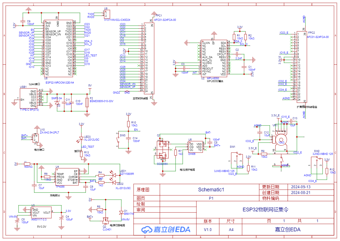
This project comprises a power supply section, an MPU6050 attitude control section, an action input control section, and a Bluetooth transmission module. Signal input processing is handled by microswitches, a remote sensor, and the MPU6050, then transmitted to the computer via the ESP32's Bluetooth module for control. The
power supply
circuit
uses a TYPE-C-6P interface. Power input is divided into two parts: one uses an AMS1117 3.3 to reduce the 5V input voltage to 3.3V to power the system; the other uses a TP4056 to charge the battery, with protection circuitry, and a CJ3401 for power conversion.
The ESP32 main control section
directly utilizes the module components, requiring only some peripheral circuitry.
Input
modules include three types: microswitches, two-dimensional joysticks, and the MPU6050 module.
Software code
details are in the attachment.
The code logic framework is also included

. Important notes: Care must be taken to control the amount of solder
during soldering. Please check for bridging of pins. Actual product images: PCB, 3D printed, soldering, and complete product images.


BOM_Board1_Schematic1_2024-09-16.xlsx
ble_mouse.zip
b87d4d8e3b12da3472fc86a1d2935108.mp4
PDF_ESP32-based Personalized Posture Mouse.zip
Altium_ESP32-based Personalized Posture Mouse.zip
PADS_ESP32-based Personalized Posture Mouse.zip
BOM_ESP32-based Personalized Pose Mouse.xlsx
92221
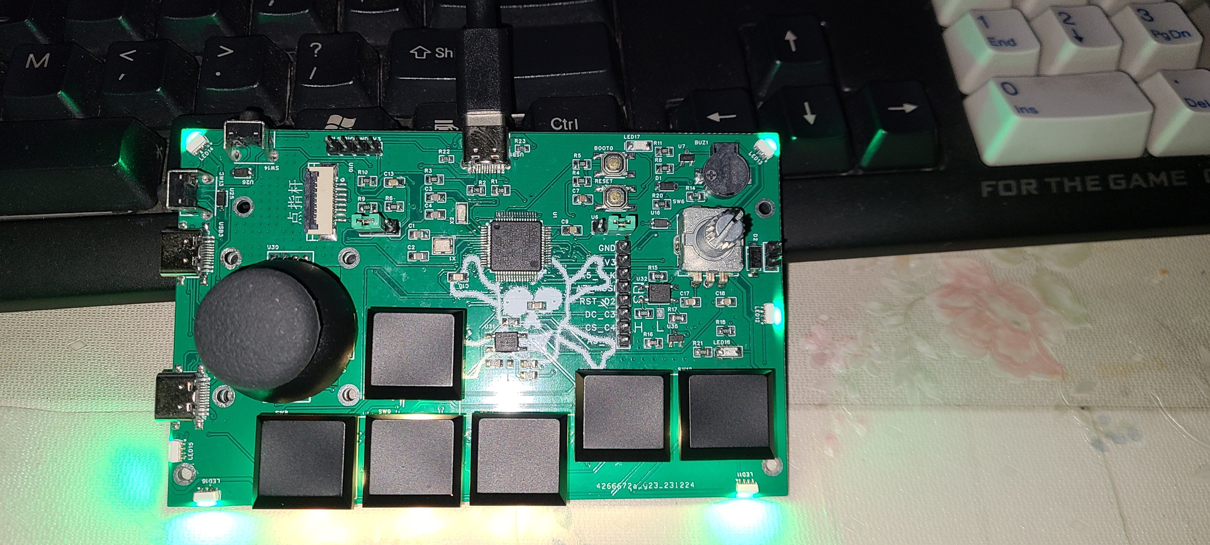
Joystick
QMK gamepad mouse
This gamepad/mouse is based on the QMK controller, supports a TrackPoint buzzer and solenoid valve interface, and has a reserved SPI interface for trackball design. It includes left, right, and scroll wheel buttons. All buttons and encoders are customizable. Pin C8 is the VCAP pin, allowing for replacement with an F103RCT6 microcontroller (no soldering required). It features a hot-swappable low-profile switch design.
20231231_163457.mp4
401y_vial.bin
PDF_Gamepad_Joystick.zip
Altium_Gamepad_Joystick.zip
PADS_Gamepad_Joystick.zip
BOM_Gamepad_Joystick.xlsx
92222
electronic


 京公网安备 11010802033920号

 1-530843-7


