Project Introduction:
ADC is an indispensable key component in electronic systems, enabling analog-to-digital conversion and providing methods for digital processing and analysis. Digital voltmeters and ammeters combine ADC technology with circuit measurement principles, accurately converting analog voltage and current signals into digital information for easy reading and analysis, making them a powerful tool for product hardware analysis. In product applications, digital voltmeters ensure the accuracy and safety of circuit design, while also providing strong support for product quality control and subsequent maintenance. This
project is a voltmeter and ammeter project based on the CW32 microcontroller, aiming to improve development capabilities from multiple dimensions.
Hardware Design:
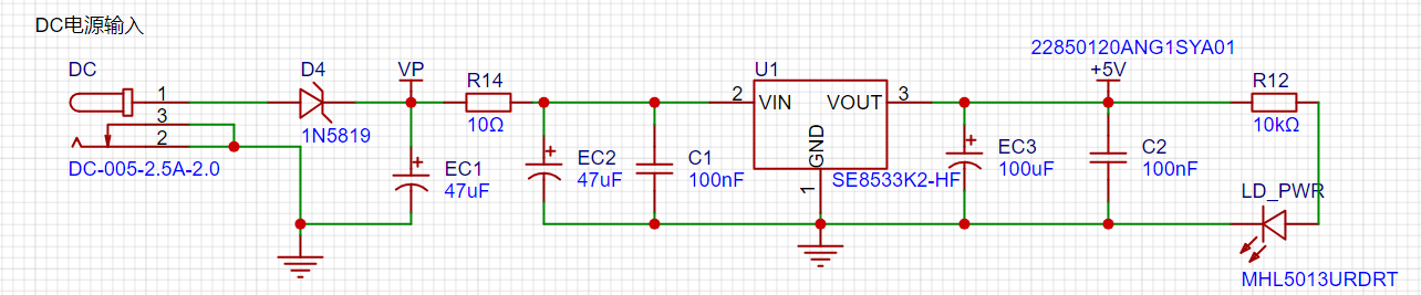
1. Power Supply Module:
LDO power supply is used here, offering advantages such as low ripple, small size, and low price. Referring to the power supply methods and application scenarios of existing finished voltmeters and ammeters, the SE8550K2 was selected as the power supply, with a maximum input voltage of 40V, meeting the requirements of most meter products.
2. Main Controller Selection
: This paper uses the Diwenxing CW32F030C8Tx minimum system board as the main controller. The selection of the controller is crucial to the overall success of the project; therefore, it is extremely important. Multiple factors must be considered to ensure the chosen controller meets the requirements and is reasonably priced.
Thus, the first step is to meet the project's needs: understand the required computing power, including clock speed, whether floating-point operations are required, memory requirements, etc. It's also necessary to determine the required number of I/O ports and important peripherals, such as ADCs and TIMs. Since the primary purpose of this project is learning, there are no major hardware restrictions, resulting in some cost overruns.
The reasons for choosing Cw as the main controller are as follows:
Wide operating temperature: -40~105℃;
Wide operating voltage: 1.65V~5.5V;
Strong anti-interference: HBM ESD 8KV; All ESD reliability meets the highest international standards;
Stable and reliable eFLASH technology;
Key project focus - Better ADC: 12-bit high-speed ADC with ±1.0LSB INL 11.3ENOB; Multiple Vref reference voltages;
Compared to equivalent ST products on the market, it exhibits superior performance.
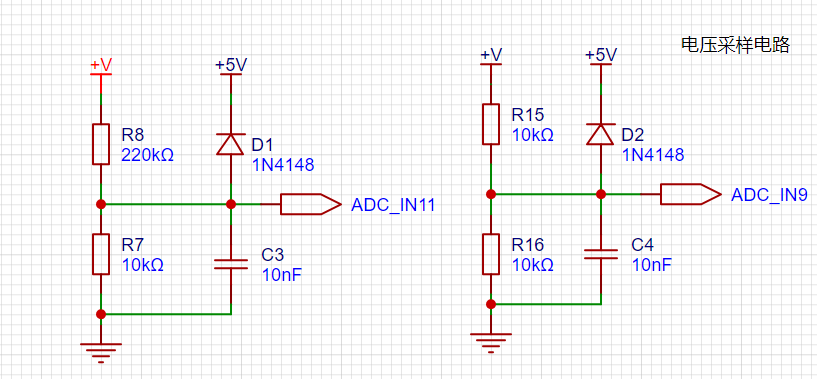
3. Voltage and Current Sampling Circuit:
This project uses a 220K+10K voltage divider resistor, resulting in a voltage division ratio of 22:1.
For
safety during debugging and learning, 30V was chosen as the maximum measured voltage, conforming to human safety standards.
The ADC reference voltage is 1.5V, which can be configured programmatically. To reduce power consumption in the sampling circuit, R7 was chosen as 10k based on experience. The high-side resistor R8 can then be calculated using the above formula. The voltage
division ratio is calculated as: ADC reference voltage / design input voltage. Based on the design parameters, 1.5V/30V = 0.05.
Similarly, the high-side resistor can be calculated using the voltage division ratio: 10K/0.05 = 200K. A standard resistor slightly higher than the calculated value was chosen, a 220K E24 series resistor.
The ADC reference voltage is calculated as follows: 1.5V/30V = 0.05, which is the input voltage.
The high-side resistance is calculated as: the low-side resistance/voltage divider ratio, which is calculated as: 10K/0.05 = 200K, which is the voltage divider
ratio. A standard resistor is selected: a resistor slightly higher than the calculated value of 200K is chosen. Typically, E24 series resistors are selected; therefore, in this project, 220K is chosen as the closest value to 200K. Range
switching
is also included in this project to explore the advantages of range switching in improving accuracy. In practice, multimeters often have multiple ranges for more accurate measurements; by adjusting different ranges, the optimal measurement accuracy of the measured point within the corresponding range can be obtained. This project uses a combination of hardware and software. First, ADC_IN11 is used to measure voltages below 30V. If voltages between 0 and 3V are to be measured, the ADC_IN9 channel is used to improve measurement accuracy.
4. The current sampling circuit
project uses a low-side current sampling circuit for current detection.
When learning and debugging, the low-side of the sampling circuit shares a common ground with the development board's meter interface, and R0 is not soldered.

The project's designed sampling current range is 0~3A. A resistor with 1% accuracy and a resistance of 100mΩ is selected as the sampling resistor. The following aspects need to be considered when selecting it:
the maximum value of the designed measurement current (3A in this project);
the voltage difference introduced by the sampling resistor (generally less than 0.5V);
the power consumption of the sampling resistor; based on the design parameters, a 1W metal-wound resistor was selected; and
the voltage multiplier across the sampling resistor. In this project, no operational amplifier is used to build the amplification circuit; the gain is 1. The selection of the sampling resistor can then be derived from the above parameters.
In high-current scenarios, the sampling resistor R0 can be replaced with a shunt for more practical use. Because this project is only for learning purposes, currents exceeding 3A will not be discussed in detail, but the selection principle remains the same.
5. Digital Tube Display:

Due to an oversight in drawing the schematic, one segment code from two common-cathode digital tubes was connected together, while the segment codes were separated. This is something that requires special attention. It took a long time to troubleshoot, and I had to use flying wires to solve the problem. There are many references for connecting common cathode and common anode digital tubes; I will only briefly mention them here. Choosing digital tubes to display current and voltage values better meets the needs of learning and debugging, and their cost and performance are both good.
In the project, actual testing showed that a 300Ω value for the current-limiting resistors (R1~R6) resulted in good brightness and non-glaring visibility of the digital tubes.
6. Power Indicator
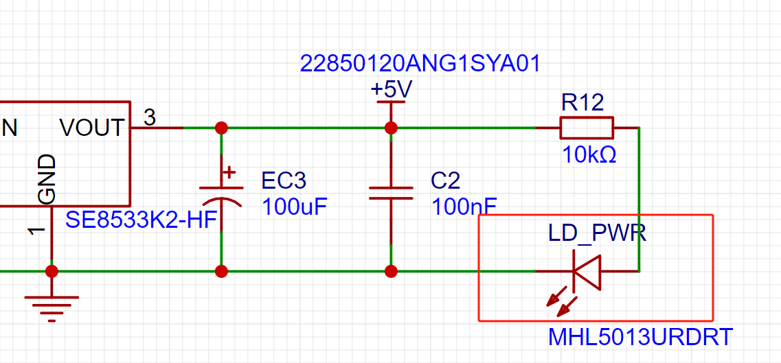
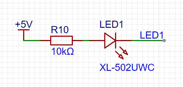
LD_PWR: This is the power indicator. Since the chip's I/O ports often have a greater sinking capacity than a sourcing capacity, LED1 is designed to be active low (on). To reduce LED power consumption, some LED brightness was sacrificed, and a 10K current-limiting resistor was chosen for the LED.
7. The button circuit design
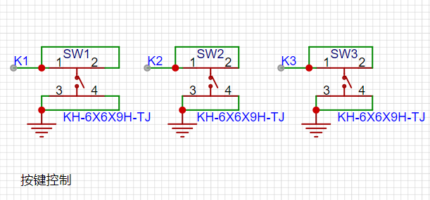
benefits from the CW32's ability to configure internal pull-up and pull-down resistors on the I/O port, eliminating the need for special external configuration. One end of the button is connected to the MCU's I/O port, and the other end is grounded. When the button is pressed, the I/O port is pulled low; the MCU detects the level change in the I/O port to trigger the corresponding function.
8. The TL431 circuit design
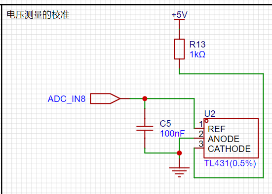
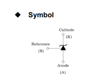
project adds an additional TL431 circuit to provide a 2.5V reference voltage for calibrating the external voltage of the AD converter. This circuit is not essential for the product; it is only used here for learning related applications.
The TL431 has the following advantages:
Precision: Its output voltage is very accurate. The TL431 used in the project has an accuracy of ±0.5%; at room temperature, the measured voltage on the board was 2.495V. Compared to common Zener diodes, its accuracy is significantly superior.
Adjustable output voltage: The output voltage adjustment range is Vref~36V, with Vref voltage approximately 2.5V.
Sinking current capability: This refers to how much current the output voltage pin can provide, which is greatly related to the resistance value (R13) and should not be less than 1mA. If there is no need for sinking current, do not design the current to be too large, as this will cause unnecessary power consumption.
Attached is an article on using JLink to program the CW32 microcontroller; it's very practical!!!
https://mp.weixin.qq.com/s/YBpDoOwrKUAyx7UVfEe6zw
Figure
1:
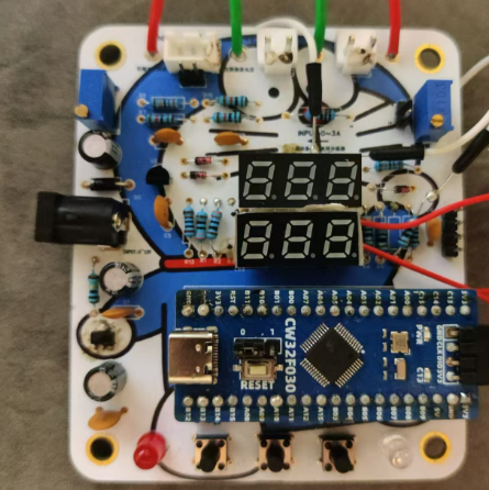
Ignoring the flying wires—this is the price of careless schematic drawing!!!
Figures 2 and 3:
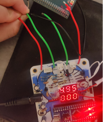
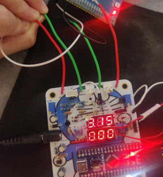
Measuring standard 3.3V and 5V voltages with minimal error.
This project was completed with reference to the JLCPCB CW32 training camp; many thanks to them!


 京公网安备 11010802033920号

 WR34615


