Project Description:
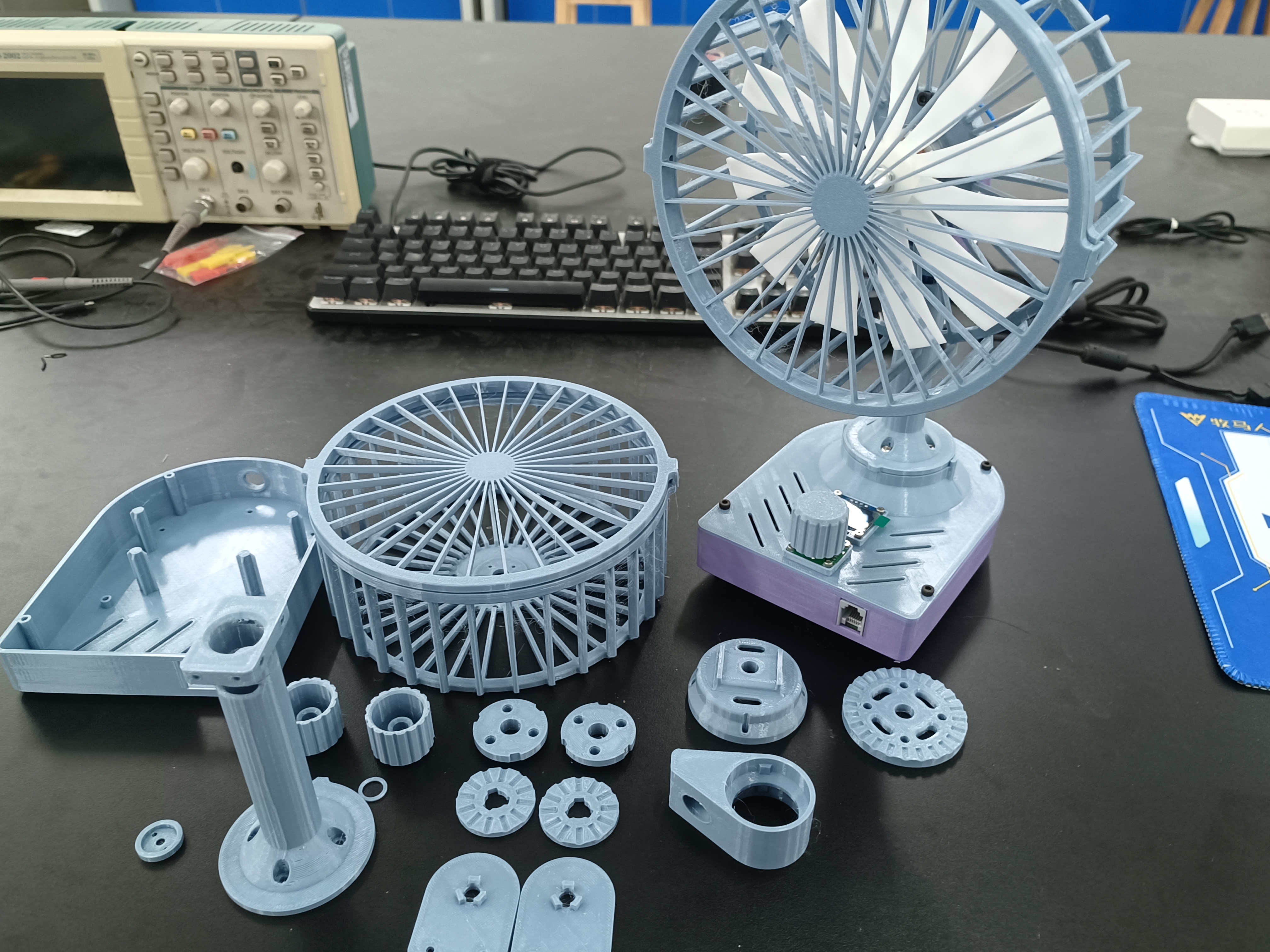
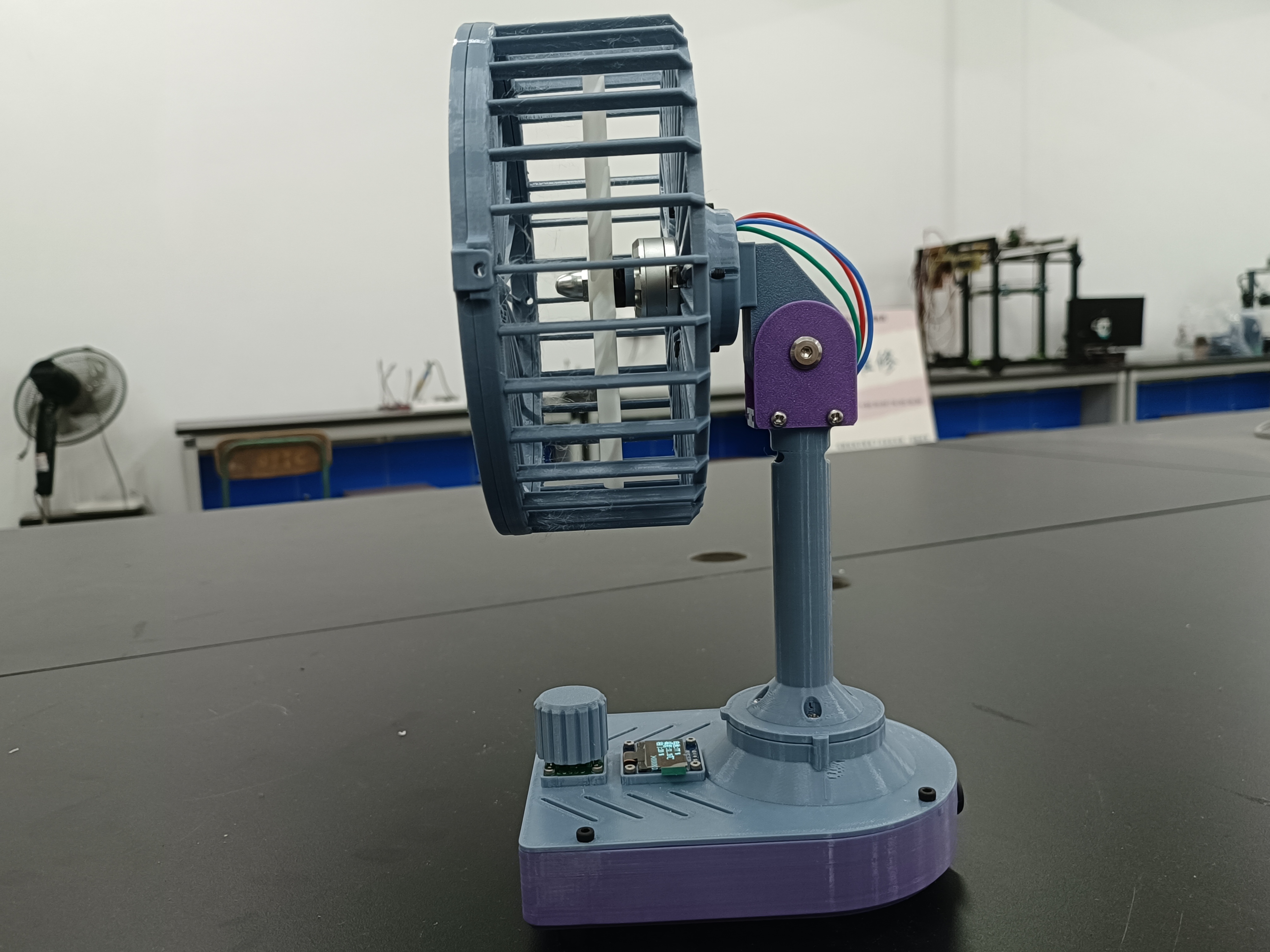
This is a brushless motor table fan. The structural components can be manufactured using 3D printing, and some metal parts are also used. It has a built-in battery that charges via a Type-C interface, allowing for simultaneous charging and use. The screen can display the battery level and heatsink temperature in real time and can be used as a thermometer when not in use.

Project Functions
1. Ratchet structure, which can adjust the pitch angle and orientation of the fan and fix it
2. Only one encoder is used for speed adjustment and start/stop, which is convenient to use and has a simple appearance
2. Closed-loop speed control, the user experience is not affected by battery voltage
3. (Jialichuang) 11-blade fan with light curing printing, low noise, large air volume, and high toughness, but safety is not guaranteed. After weighing the pros and cons, it is used
Update Log
24/08/26:
(1) The program has been optimized to improve the startup speed and success rate
24/08/29 : (1)
Fixed the problem of the OLED screen freezing after a period of use
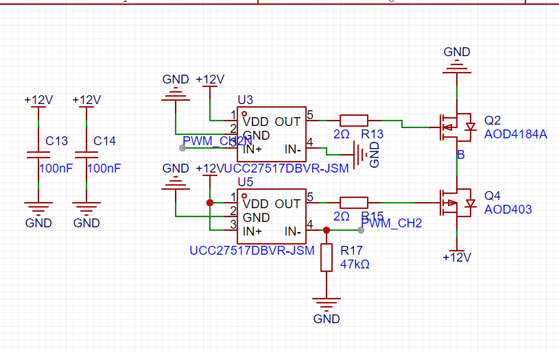
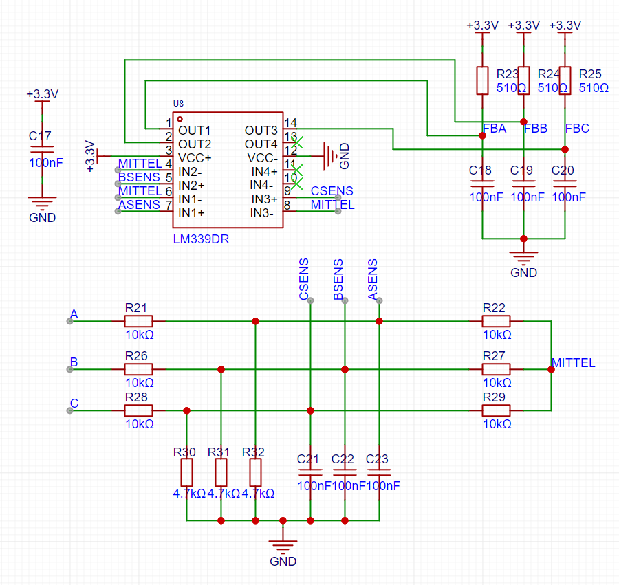
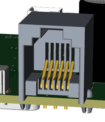
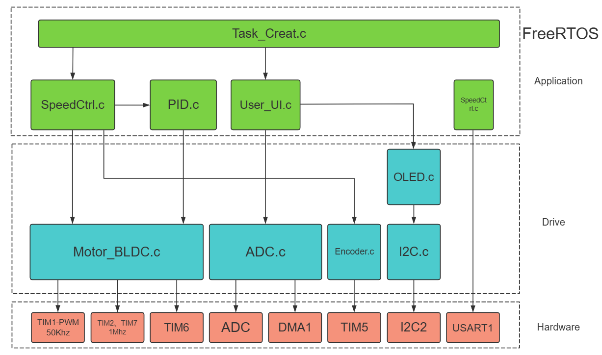
(2) Added 2212 self-locking motor dedicated silent fan blades 24/08/31: (1) Fixed the problem in the comparator interrupt function, which caused the motor to make abnormal noise at high speed (2) The fixed delay of 30 degrees electrical angle commutation was changed to a freely settable delay angle 24/9/1: (1) Optimized part of the speed control PID code, reduced some noise, and changed the speed sampling to be performed in the timer interrupt 24/9/10: (1) Improved the problems with OLED by using DMA to transfer data. (2) Improved some abnormal issues. (3) The model file provides assemblies for reference during assembly. (4) Provided a new fan model with a better appearance and slightly increased airflow. (5) The 2212 motor is not very effective, and the fan blades are a mess. It is not recommended to use it. Principle Analysis (Hardware Description) Power Supply Section: PD/Fast Charging Protocol Spoofing: A CH224K transistor is used to induce 12V. When spoofing is successful, the PG output is low. The main controller detects this and displays a prompt on the screen. Main Control Power Supply : A DC-DC converter is used for higher efficiency and energy saving . Power Stage: An upper-side PMOS and lower-side NMOS design is adopted, achieving a duty cycle of up to 100%. It is also equipped with a high-efficiency gate driver, resulting in very low heat generation from the MOS transistors . //Note: Do not solder the IN- resistor connected to the gate driver; that is, R16, R17, and R20 on the board do not need to be soldered. // This is the gate waveform when the gate resistance is 2 ohms. You can continue to adjust it as needed. Zero-Crossing Detection Circuit: The correctness and timing of commutation greatly affect motor noise and efficiency. Below is a common zero-crossing detection resistor network. I used... An external comparator was used for further processing, which is compatible with microcontrollers without built-in comparators. I also believe that using a comparator for detection is faster and more accurate. However, I added an RC filter at the output to remove glitches, but I feel that it might be better without it. Early test boards did not have this filter, and software filtering of glitches seemed to result in less noise. Those who like to tinker can try it without soldering and modifying the code. Programmer interface: This is an RJ1 telephone jack, which is a rather special design. A separate programmer is needed for this, which you may find troublesome. However, you can use this programmer in your future projects. This interface is very durable, easy to plug and unplug, and has a secure connection. Software code overall framework Part code details: How to know when to switch phases and which phase to switch to? This issue can be referenced at https://blog.csdn.net/snail_dongbin/article/details/82803076. In the code implementation, the interrupt trigger of the three output I/O ports of the comparator is configured to be edge-triggered, and both rising and falling edges will trigger the interrupt. In the interrupt, the level state of the three I/O ports is read, and then the phase to be switched is determined based on this level state. uint8_t BLDC_ReadFB(uint8_t filter) { uint8_t date; while (filter--) { date = GPIOA->IDR & 0xE0; // 1110 0000 PA7 PA6 PA5 } return date >> 5; } void BLDC_XPHAS_Close(void) { uint8_t rotorloca; rotorloca = BLDC_ReadFB(1); switch (GlobalDir) { case 1: switch (rotorloca) { case 5: // C+B- BLDC_MosCtrl(CpBn); EXTI->IMR |= EXTI_IMR_MR5; // Enable phase A interrupt break; case 4: // C+A- BLDC_MosCtrl(CpAn); EXTI->IMR |= EXTI_IMR_MR6; // Enable phase B interrupt break; case 6: // B+A- BLDC_MosCtrl(BpAn); EXTI->IMR |= EXTI_IMR_MR7; // Enable phase C interrupt break; case 2: // B+C-


BLDC_MosCtrl(BpCn);
EXTI->IMR |= EXTI_IMR_MR5; // Enable A-phase interrupt
break;
case 3: // A+C-
BLDC_MosCtrl(ApCn);
EXTI->IMR |= EXTI_IMR_MR6; // Enable B-phase interrupt
break;
case 1: // A+B-
BLDC_MosCtrl(ApBn);
EXTI->IMR |= EXTI_IMR_MR7; // Enable C-phase interrupt
break;
default:
break;
}
break;
........
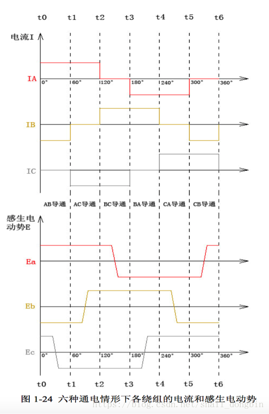
The induced electromotive force in the diagram, after being processed by the comparator, can be viewed as high and low levels. Arranging abc into three binary numbers from low to high, we can see that when the floating phase voltage jumps, the obtained numbers correspond one-to-one with the cases in the code above. The code example above is the reverse of the order in the diagram, from CB to AB. A pattern can be observed from the numbers in the case statements: the two phases to be conducted correspond to the numbers in the case statements (+ corresponds to 1, - corresponds to 0), while the floating phases alternate between 0 and 1. If the bit representing the floating phase in each case statement is inverted, the code corresponding to the inversion is obtained.
By utilizing the COM event function of the advanced timer TIM1, seamless switching of the switching states of the six MOSFETs can be achieved. To do this, the initialization function should call `TIM_CCPreloadControl(TIM1, ENABLE);` // Enable preloading of complementary output enable registers `
void BLDC_MosCtrl(MoState_TypeDef`)
{
`TIM1->CCER &= ~(TIM_CCER_CC1E | TIM_CCER_CC2E | TIM_CCER_CC3E |
TIM_CCER_CC1NE | TIM_CCER_CC2NE | TIM_CCER_CC3NE);` // Clear PWM output
`TIM1->CCMR1 |= TIM_CCMR1_OC1M;`
`TIM1->CCMR1 &= ~TIM_CCMR1_OC1M_0;` // Reset complementary output A to PWM mode `
TIM1->CCMR1 |= TIM_CCMR1_OC2M;` `
TIM1->CCMR1 &= ~TIM_CCMR1_OC1M_0;` ~TIM_CCMR1_OC2M_0; // Reset B phase complementary output to PWM mode
TIM1->CCMR2 |= TIM_CCMR2_OC3M;
TIM1->CCMR2 &= ~TIM_CCMR2_OC3M_0; // Reset C phase complementary output to PWM mode
switch (mostate) {
case ApBn:
TIM1->CCER |= TIM_CCER_CC1E;
TIM1->CCER |= TIM_CCER_CC2NE;
TIM1->CCMR1 |= TIM_CCMR1_OC2M_0;
TIM1->CCMR1 &= ~TIM_CCMR1_OC2M_1; // Force B phase lower transistor to turn on
break;
case CpBn:
TIM1->CCER |= TIM_CCER_CC3E;
TIM1->CCER |= TIM_CCER_CC2NE;
TIM1->CCMR1 |= TIM_CCMR1_OC2M_0;
TIM1->CCMR1 &= ~TIM_CCMR1_OC2M_1; // Force B-phase tube opening
break;
case CpAn:
TIM1->CCER |= TIM_CCER_CC3E;
TIM1->CCER |= TIM_CCER_CC1NE;
TIM1->CCMR1 |= TIM_CCMR1_OC1M_0;
TIM1->CCMR1 &= ~TIM_CCMR1_OC1M_1; // Force A-phase tube opening
break;
case BpAn:
TIM1->CCER |= TIM_CCER_CC2E;
TIM1->CCER |= TIM_CCER_CC1NE;
TIM1->CCMR1 |= TIM_CCMR1_OC1M_0;
TIM1->CCMR1 &= ~TIM_CCMR1_OC1M_1; // Force A-phase tube opening
break;
case BpCn:
TIM1->CCER |= TIM_CCER_CC2E;
TIM1->CCER |= TIM_CCER_CC3NE;
TIM1->CCMR2 |= TIM_CCMR2_OC3M_0;
TIM1->CCMR2 &= ~TIM_CCMR2_OC3M_1; // Force C-phase tube opening
break;
case ApCn:
TIM1->CCER |= TIM_CCER_CC1E;
TIM1->CCER |= TIM_CCER_CC3NE;
TIM1->CCMR2 |= TIM_CCMR2_OC3M_0;
TIM1->CCMR2 &= ~TIM_CCMR2_OC3M_1; // Force C-phase tube opening
break;
default:
BLDC_OstClaer();
break;
}
TIM1->EGR |= TIM_EGR_COMG; // Update the above registers
}
As shown in the code above, the enable register and mode register of TIM1 are both preloaded. Reading and writing their contents will not immediately change the output state of the PWM channel. It will only change when a COM event bit is written to the event generation register at the end. In this way, all 6 PWM output channels can be changed at the same time.
How to achieve 30-degree electrical angle commutation with delay?
TIM7 uses single-count mode. After an external interrupt connected to the comparator is triggered, TIM7 is enabled to start counting. Then, within the TIM7 interrupt, BLDC_GetDelayAngleVal(30) is called. This function calculates the time elapsed between two adjacent commutations and assigns the return value to the timer's ARR register to determine the delay time after the next external interrupt triggered by the comparator.
void TIM7_IRQHandler(void)
{
if (TIM7->SR & TIM_SR_UIF) { // Check the interrupt flag
TIM7->ARR = BLDC_GetDelayAngleVal(30);
BLDC_XPHAS_Close();
// EXTI->IMR |= (EXTI_IMR_MR5 | EXTI_IMR_MR6 | EXTI_IMR_MR7); // Enable commutation interrupt
}
TIM7->SR &= !TIM_SR_UIF; // The specific implementation of clearing
the interrupt flag
involves reading the count value of a timer that is constantly in a timing state, saving the previous count value, and subtracting the previous count value from the current count value to obtain the interval between two commutations. Since the electrical angle interval between two commutations is 60 degrees, half of the difference is taken, or processed as shown in the code below to implement an optional delay angle. The if statement is for overflow judgment. Because the CNT value ranges from 0 to 65535, if the previous CNT value is close to 65535, the current value obtained is likely to be a smaller value, requiring processing. The code snippet
`uint16_t BLDC_GetDelayAngleVal(uint16_t angle)
{
float delayval;
Anglast_cntval = Angcntval;
Angcntval = TIM2->CNT;
delayval = Angcntval - Anglast_cntval;
if (delayval < 0) { delayval
= 65535 + delayval;
}
delayval /= (60 / angle);
delayval` is used to determine the delay angle. += 0.5; // Rounding
return delayval;
}
How to start the motor?
As we all know, when a motor stops rotating, it cannot generate back electromotive force, so the current position of the motor rotor is unknown. My strategy is to first call BLDC_BackLoca() to forcibly drag the rotor to a certain position.
void BLDC_BackLoca(void)
{
BLDC_SetGlobalPwm(0.15);
BLDC_MosCtrl(ApBn);
vTaskDelay(300)
; BLDC_MosCtrl(ApCn)
; vTaskDelay(300);
BLDC_MosCtrl(ApBn);
vTaskDelay(300);
}
Then start timer 6 to drag back and forth between two adjacent phases at a fixed time interval, creating a rapid jittering effect. After a certain number of times, disable interrupts and enable the interrupt line connected to the comparator to enter closed-loop commutation
void BLDC_OpenLoopStartup_ISR(void)
{
static uint8_t Temp;
static uint16_t xphascount;
static uint8_t state = BLDC_start;
switch (state) {
case BLDC_start:
// BLDC_OpenLoopCtrl(startcycle, startperiod, GlobalDir, 1);
xphascount = 0;
Temp = 1;
state = BLDC_Pull;
break;
case BLDC_Pull:
if (Temp) {
BLDC_MosCtrl(ApBn);
Temp = 0;
} else {
BLDC_MosCtrl(ApCn);
Temp = 1;
}
state = BLDC_counting;
break;
case BLDC_counting:
if (xphascount >= 10) {
xphascount = 0;
// startperiod -= 100;
state = BLDC_speedup;
} else {
xphascount++;
state = BLDC_Pull;
}
break;
case BLDC_speedup:
state = BLDC_start;
xphascount = 0;
StartUpFlag = 1; // Set the start flag to 1
TIM6->CR1 &= ~TIM_CR1_CEN; // Turn off timer 6 and exit open-loop control
BLDC_CloseLoopStartUp(0.1, 1); // Start closed-loop control:
`xQueueSendFromISR(xQueue_MotorStartUp, &StartUpFlag, NULL);` // Send start signal: `
break;`
default:
`BLDC_OstClaer();` // Shut down all MOSFETs: `
break;
`
Firmware
download
and firmware burning:
First, install WCHISPTool. The software interface is shown in the image, and the options are the same. In the User Program File section, select the firmware to be burned.

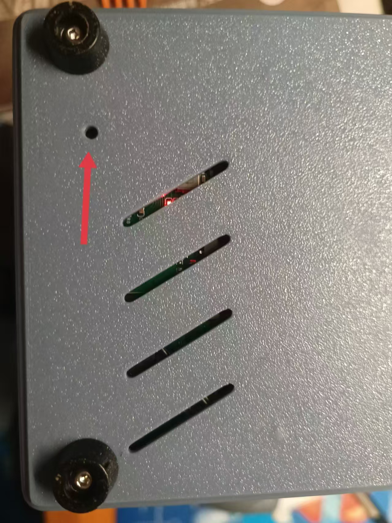
Use tweezers to short-circuit the pad below the arrow and the pin indicated by the arrow, and simultaneously insert the USB cable to connect to the computer. At this time, you will hear a prompt sound from the computer, and the device will automatically appear in the USB device list. Then you can release the tweezers and click Download.
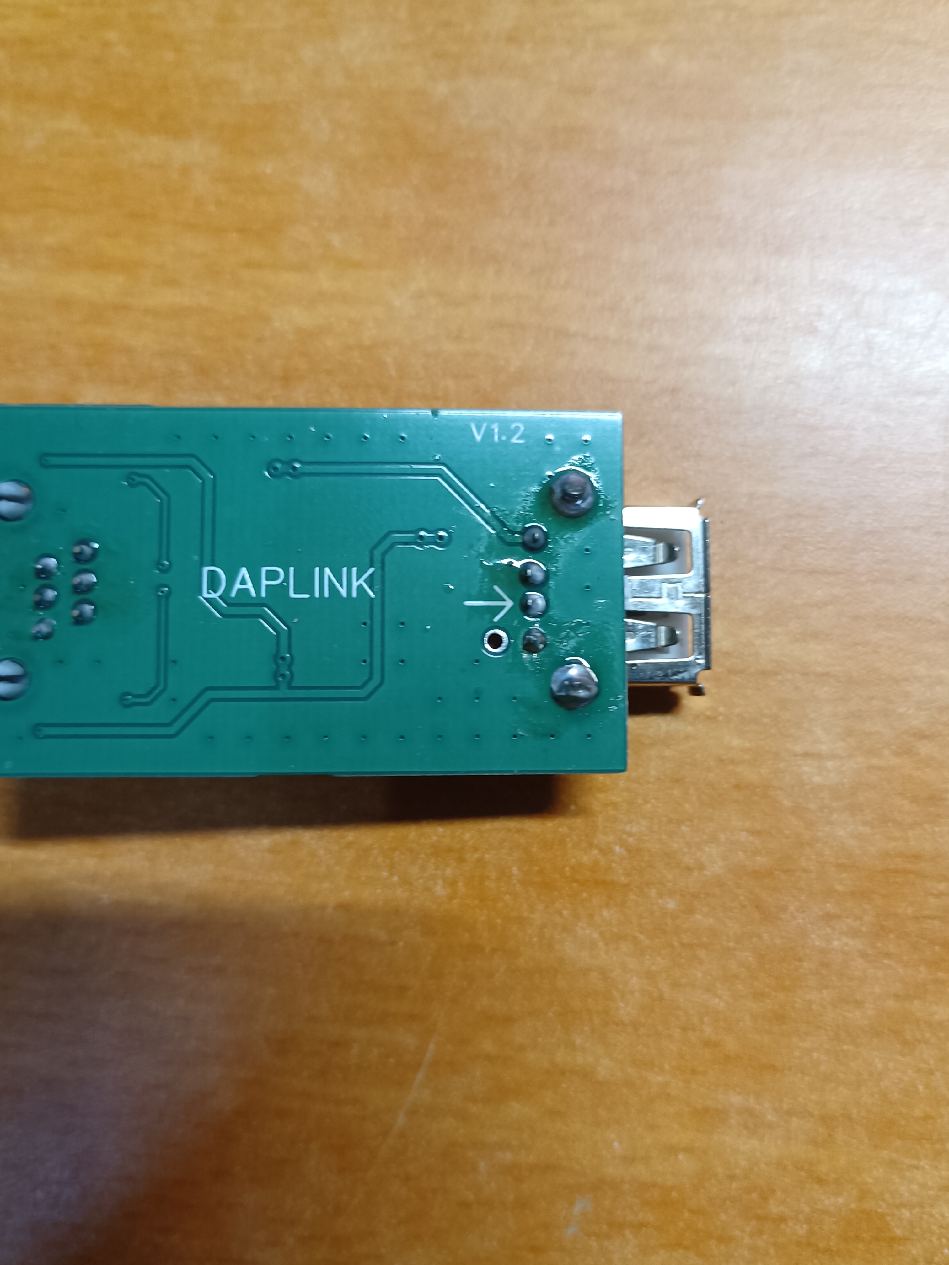
This firmware burner is actually WCHLINK. After burning the firmware, the default mode is RCICV. After unplugging the USB cable, press and hold the button on the front of the board and then plug it back in. Wait for both LEDs to light up, indicating that it has switched to ARM mode.
Motherboard firmware burning:
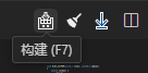
Method 1: If you have VS Code installed and have configured the EIDE plugin environment, you can directly click Workspace in the package,
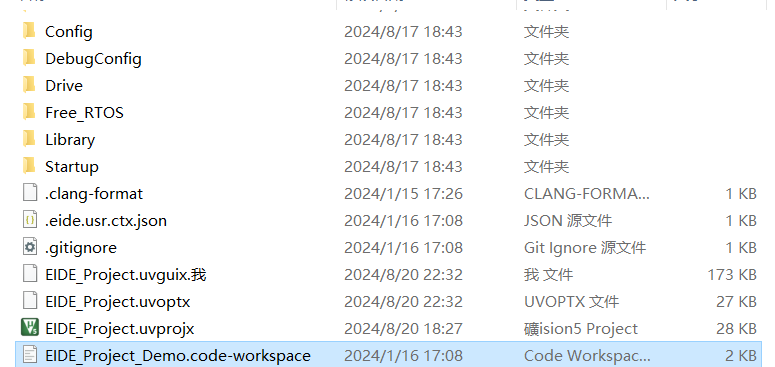
then click Build in the upper right corner, and then click Burn.

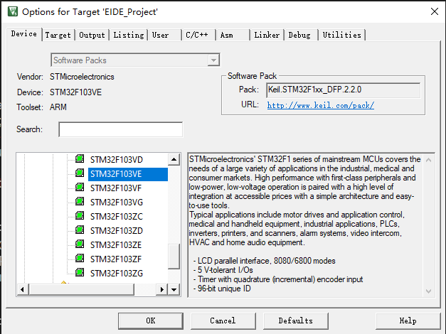
Method 2: Click Keil project, open it, click Magic Wand, and select STM32F103VE as Device.
Select DAP for Debug,
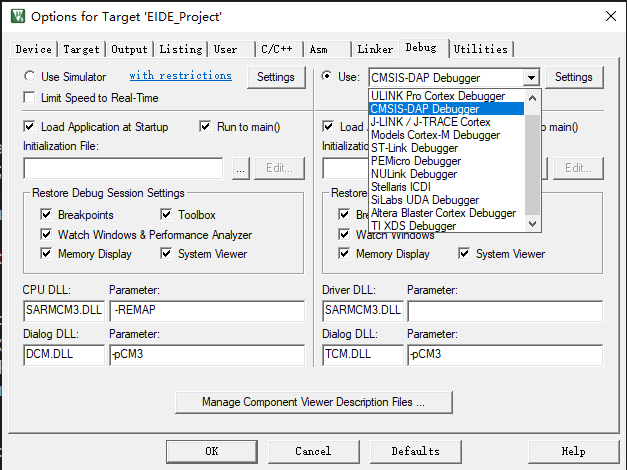
click Utilities-setting

and check all options, then compile and flash. Normally, I've already selected all the steps for you. You can check
the assembly process
. First, heat-fit the motor cable compartment and the base ratchet disc with a 8mm nut and
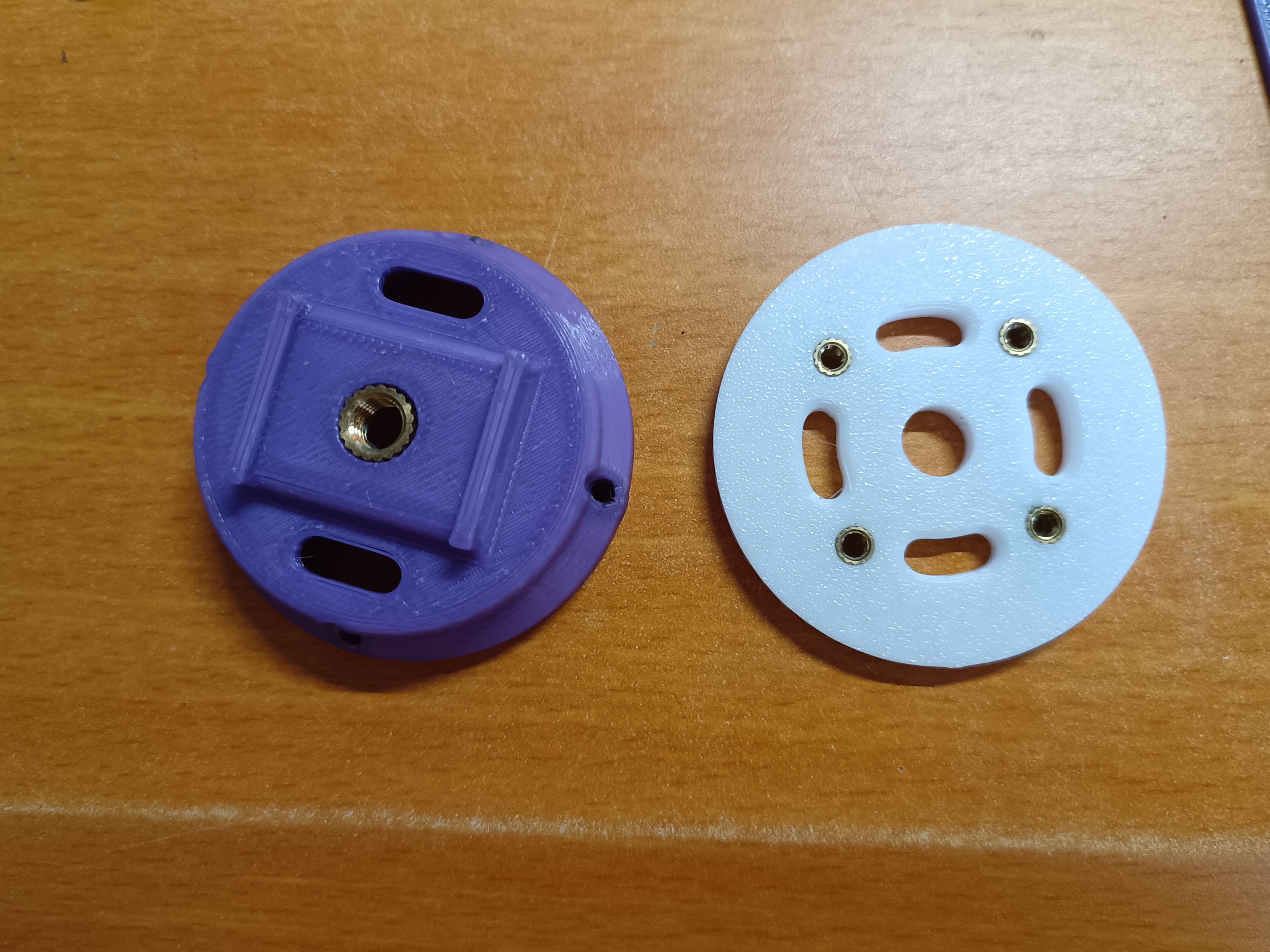
press the ball-head plunger into the part shown in the picture.
Press the ratchet disc into the connecting piece.

Install the part with the ball-head plunger just pressed into the pitch seat.
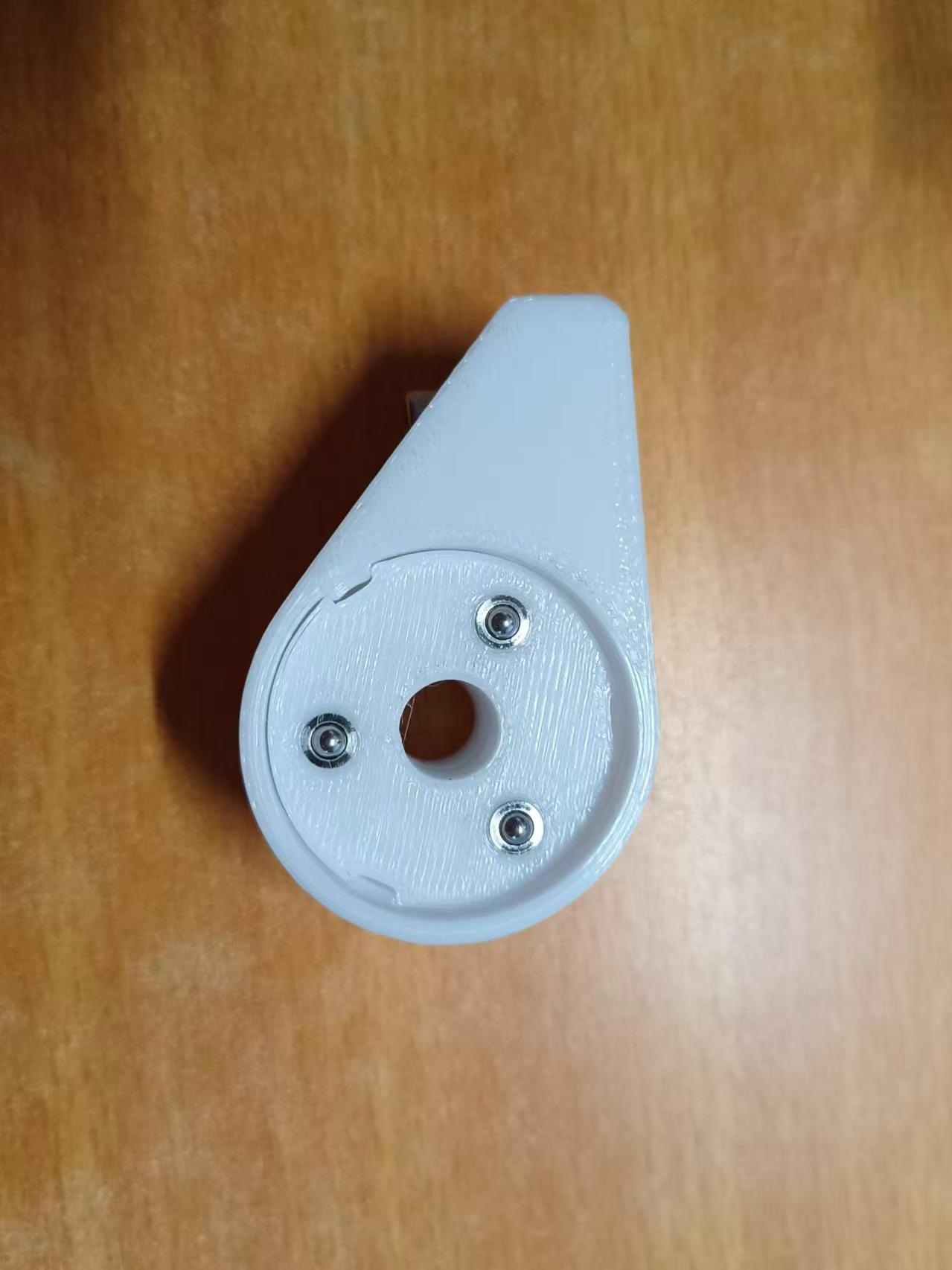
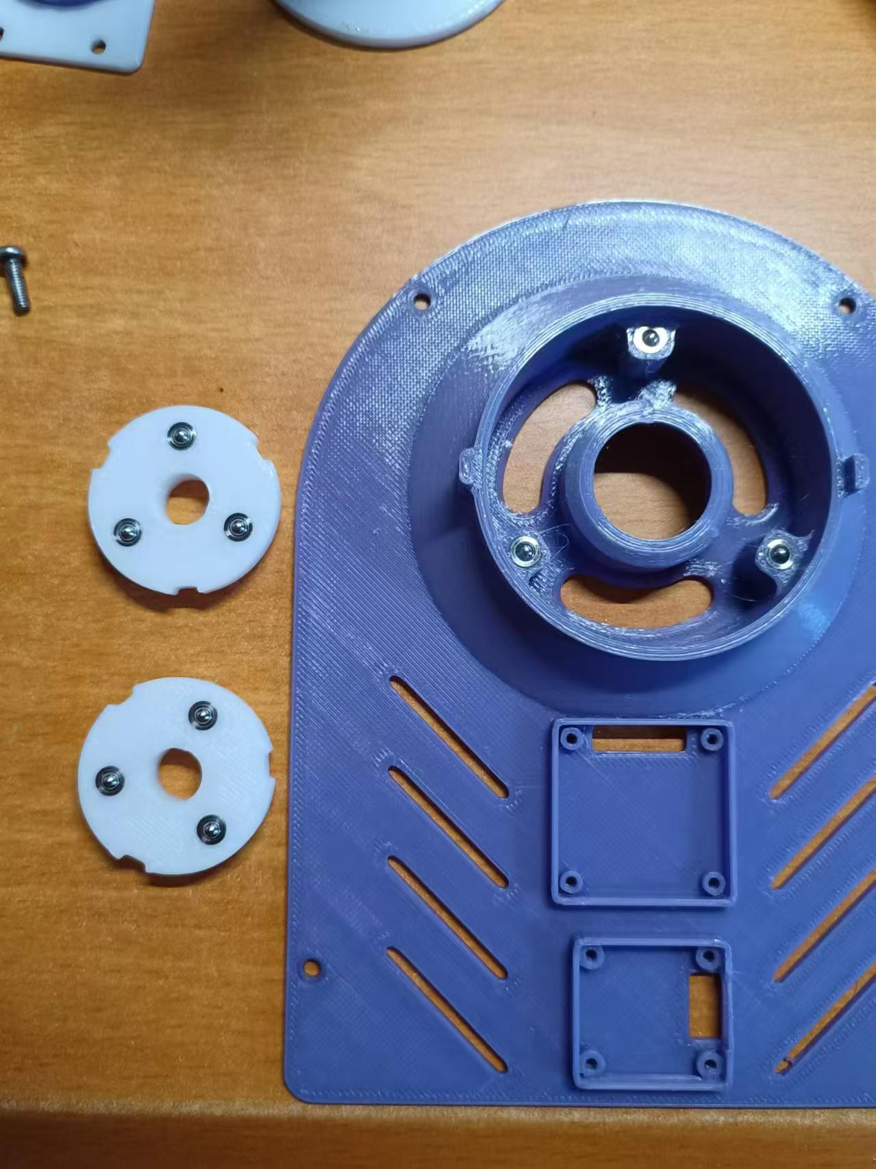
Place a 608 bearing and press it all the way down.
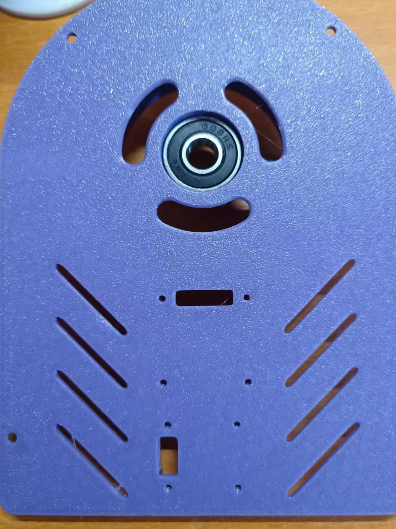
Place the ratchet disc into the base and tighten it with locking screws. Place a washer on the bearing and screw contact surface.
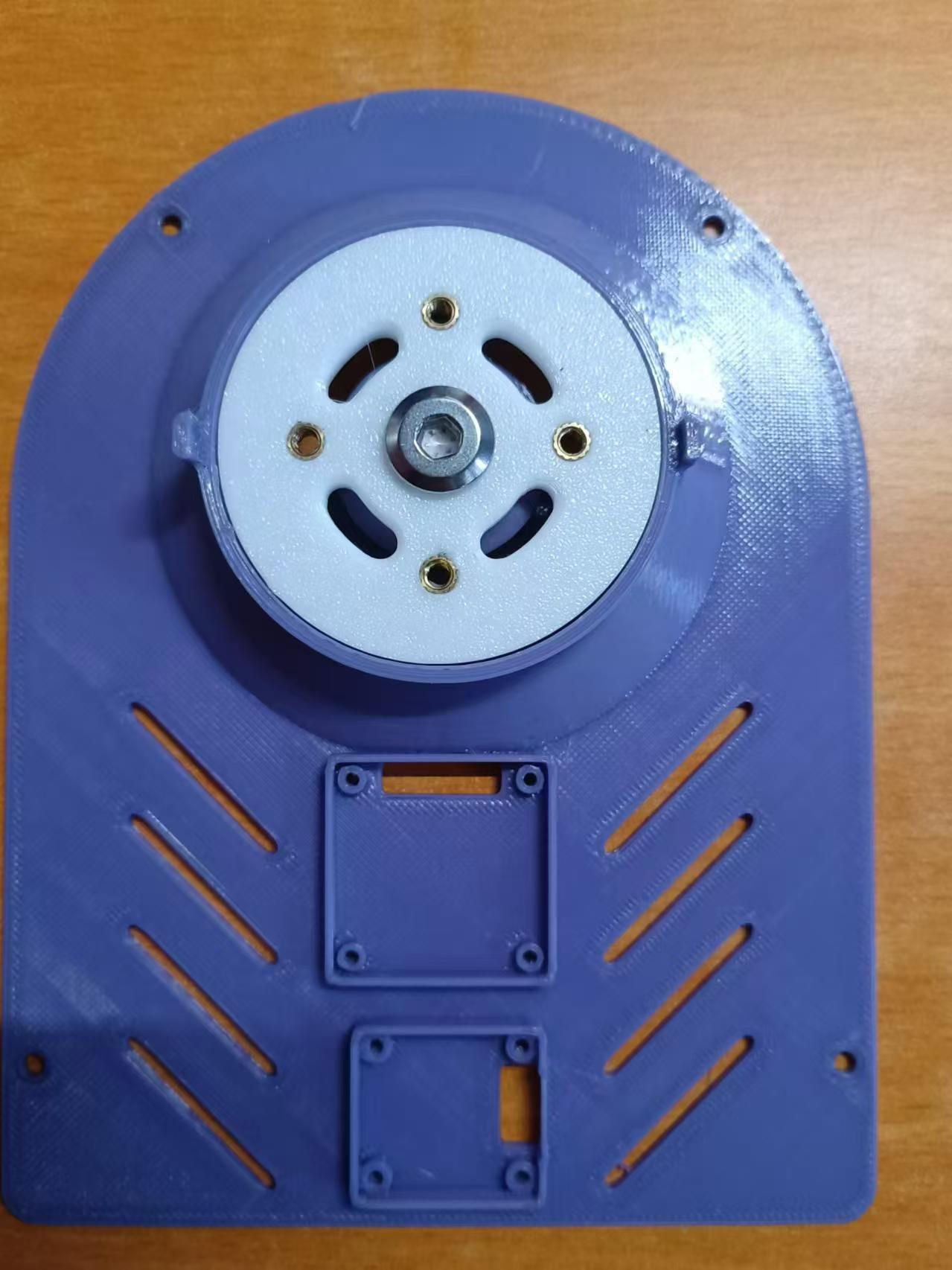
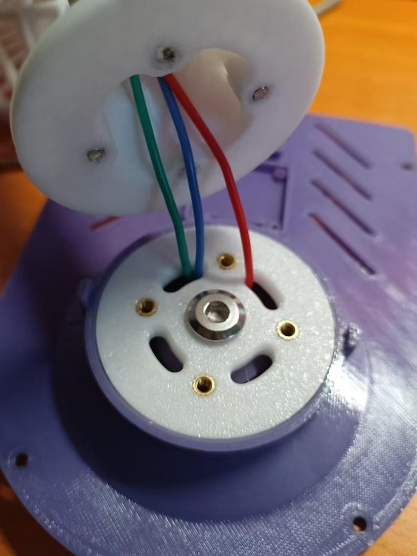
Assemble the parts shown in the picture. Use M3X12 screws for the fan cover and M3X6 screws for the support rod. Use an electric screwdriver to drive them in; they are very sturdy. Remember to leave enough motor cable length. Finally, tighten the connecting piece with locking screws.


Pass the motor cable through the hole in the base ratchet disc, then use M3X6 screws to fix the support rod to the base ratchet disc.
Fix the OLED module with the soldered PH terminal wire and the encoder module to the base using M2X6 screws.
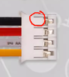
Due to a design error, the Type-C on the motherboard... The order of the battery connectors is reversed compared to the purchased materials. You can either solder the connectors backwards or manually modify the wiring sequence. The wiring sequence is already marked on the motherboard. Simply use tweezers to slightly pry up the plastic piece shown in the diagram to easily pull out the terminal wires.
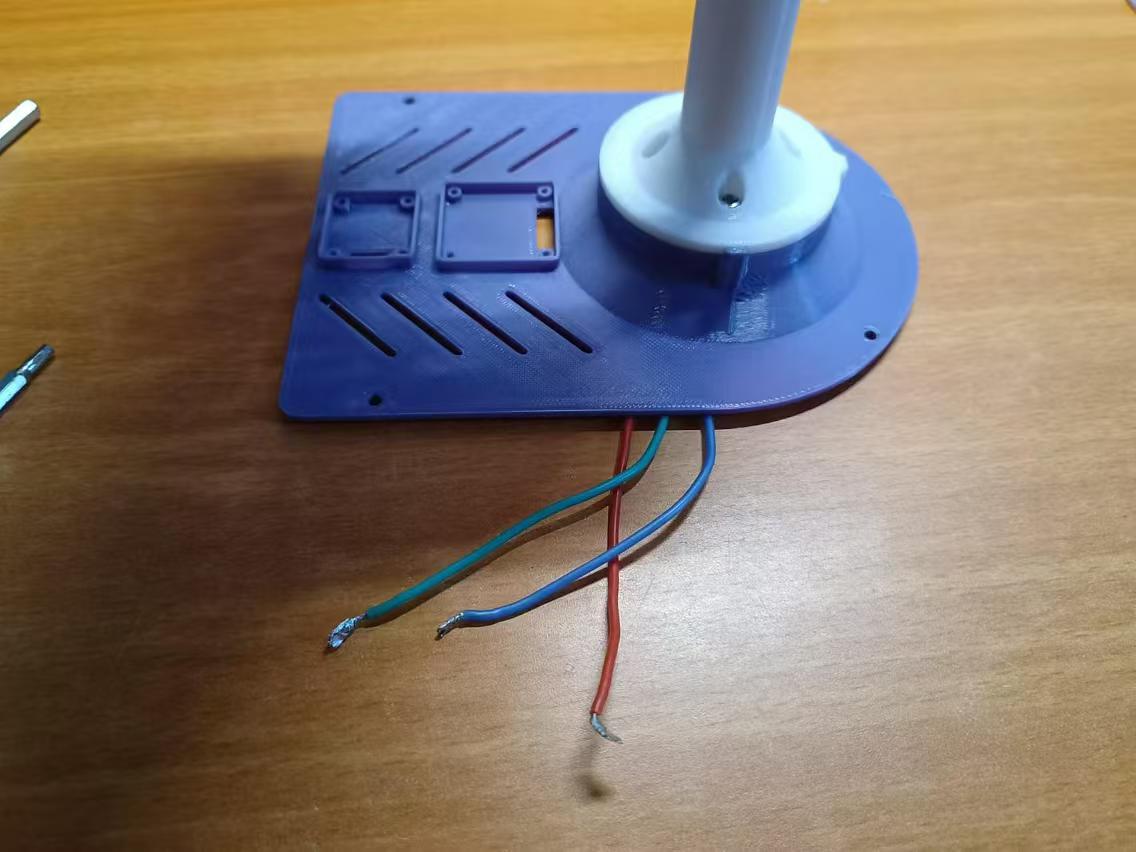
Solder the motor wires to the motherboard's surface-mount component side, then use M3X6 screws to fix the motherboard to the base housing. Add a washer between the motherboard and the screws. Note that the Type-C connector requires removing the battery housing to access the connector, so you'll eventually need to disconnect the wires. It's recommended to simply modify the wiring sequence.
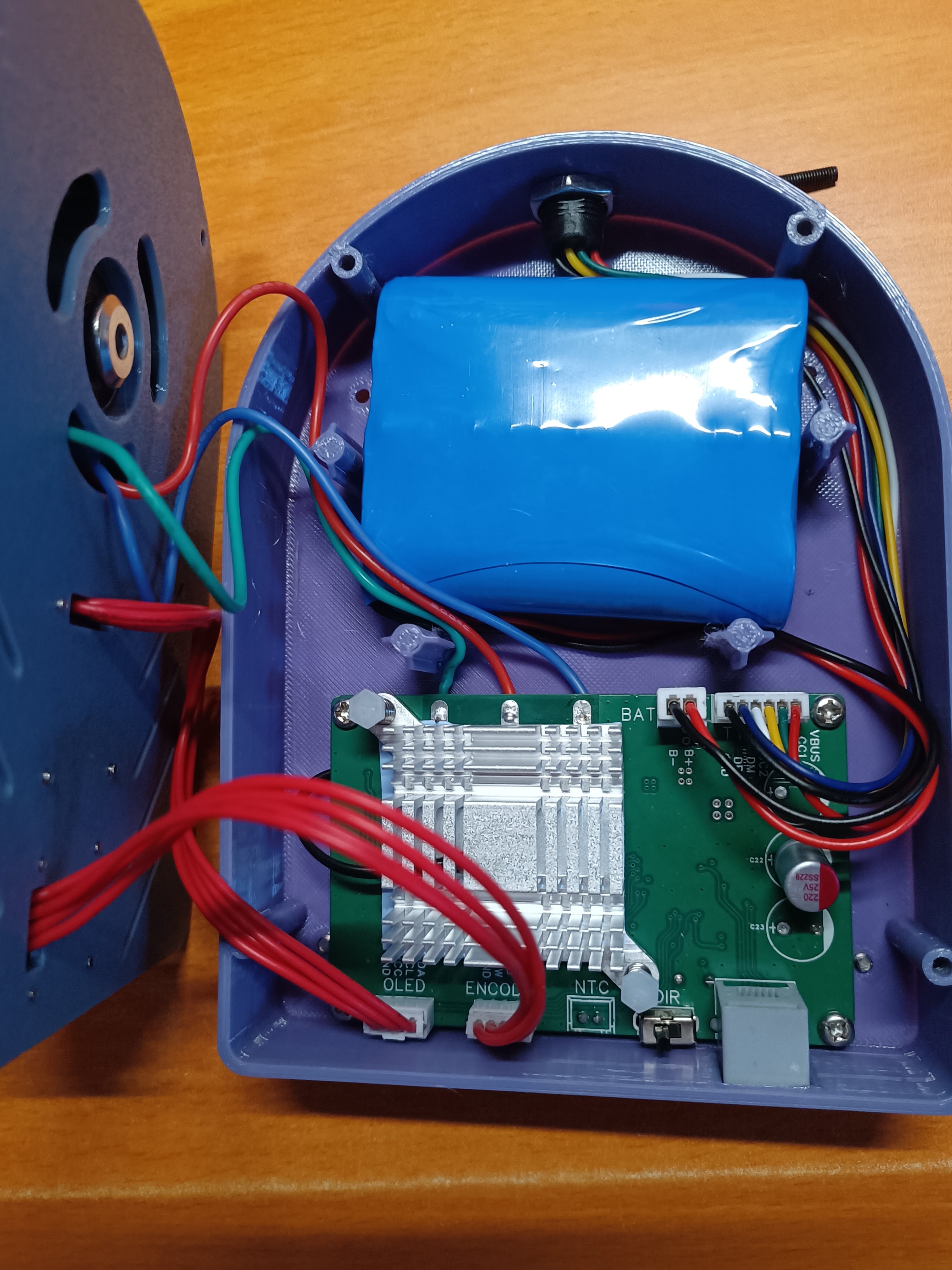
After confirming that the battery's positive and negative wire sequences correspond to the markings on the motherboard, connect them correctly. Observe that the OLED display is normal, then press the encoder to start the fan. If the rotation direction is incorrect, press the fan to stop, or directly remove the battery. Toggle the switch marked DIR. If your motor has a positive thread, the correct direction is counter-clockwise; if it has a negative thread, the correct direction is clockwise. If the direction is incorrect, the motor will not be able to self-lock the blades, causing a hazard.
Finally, tidy up all the wires, place the base on the bottom housing, and tighten it with M3X12 screws. Then install the three feet on the bottom housing, and you can start using it!
My current model files provide fan covers with inner diameters of 140 and 150 mm, and both sizes offer three motor mounting options: the readily available MT2204, RS2205, and 1806 motor mountings. I personally use the 2204, which requires a separate propeller mount. You can choose according to your preference and actual needs.
If any abnormalities occur and the device malfunctions, you can restore it by pressing the reset button through the small hole on the bottom shell.
WCHLink.zip
BLDC Desk Fan Demo Video.mp4
BLDC Desk Fan Material List_2204.xlsx
DAPLINK Shell Model.zip
BLDC Table Fan Model.zip
Model Print Files.zip
EIDE_FreeRTOS brushless desktop fan program 240910.zip
PDF_BLDC Desktop Fan.zip
Altium_BLDC Desktop Fan.zip
PADS_BLDC Desktop Fan.zip
BOM_BLDC Desktop Fan.xlsx
92363
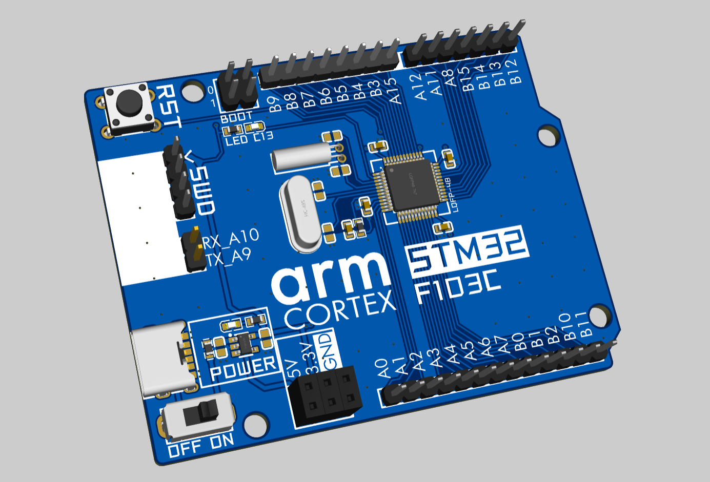
STM32F103C8T6 Uno Development Edition
STM32F103C8T6 development board using Arduino Uno form factor
The STM32F103C8T6 development board using the Arduino Uno form factor
is shaped and sized similarly to the official DXF, with adjustments to the pin arrangement and placement. It is not compatible with shield-type boards
with all pins exposed, uses a Type-C power supply, and includes a power switch.
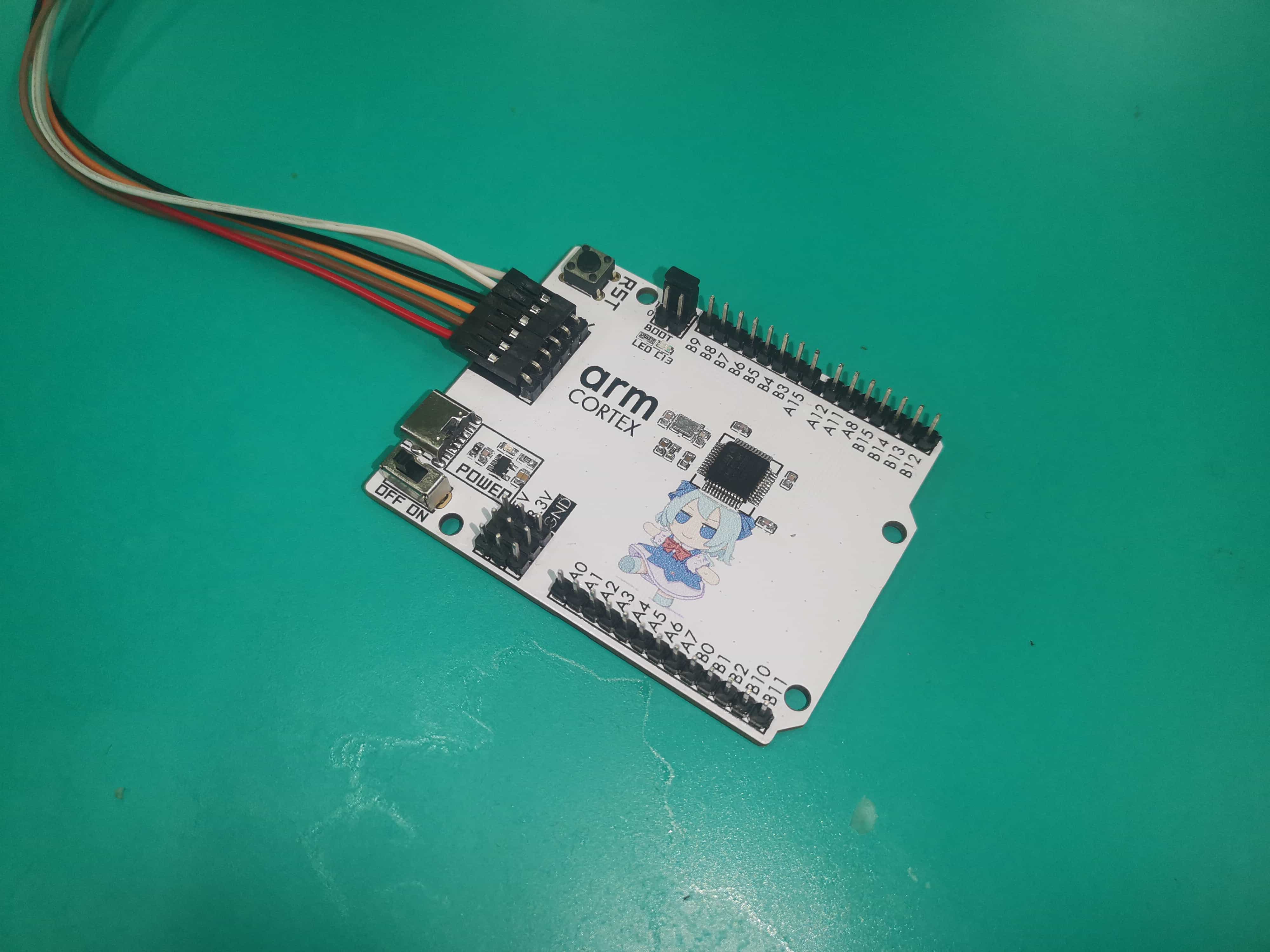
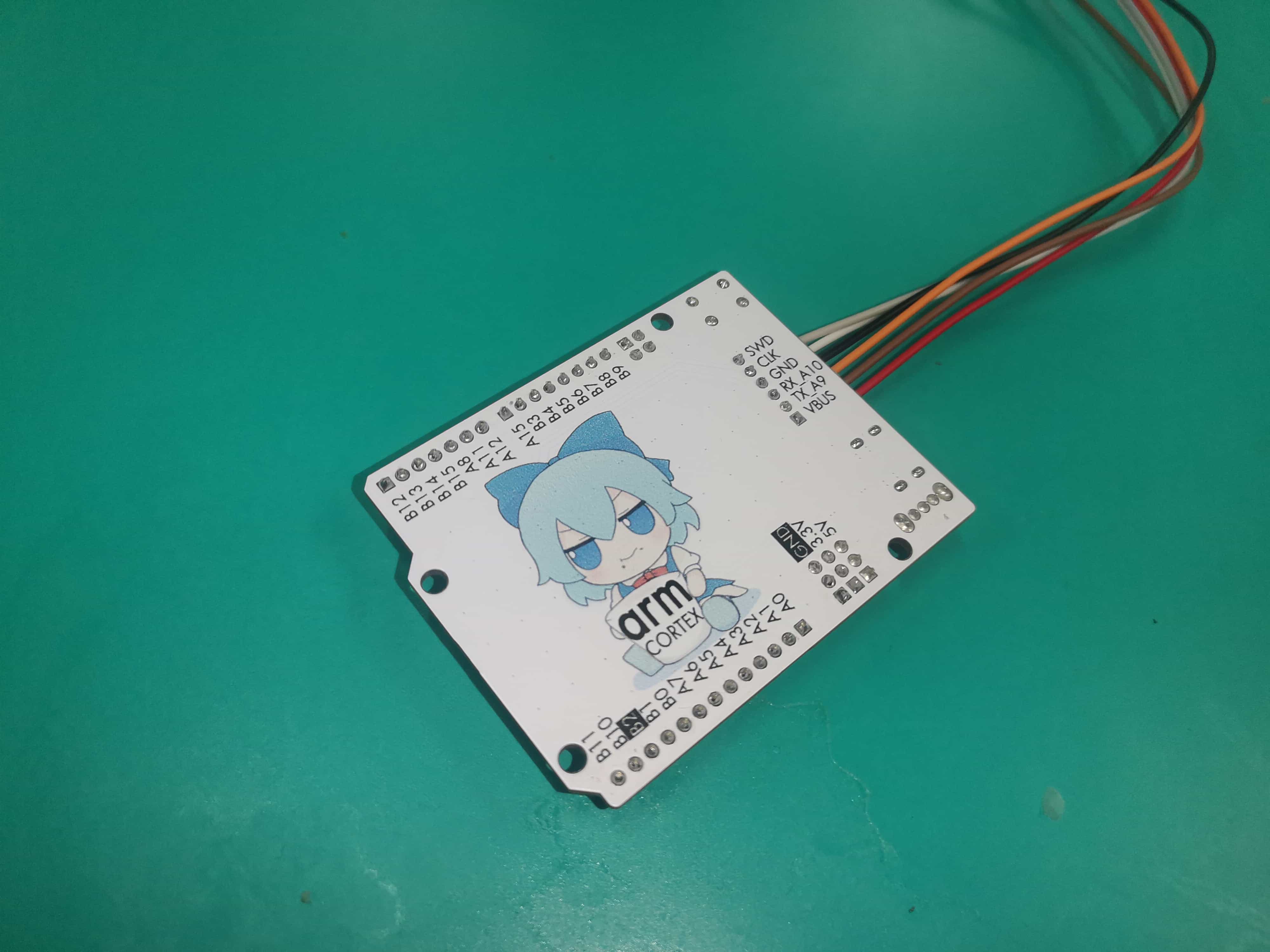
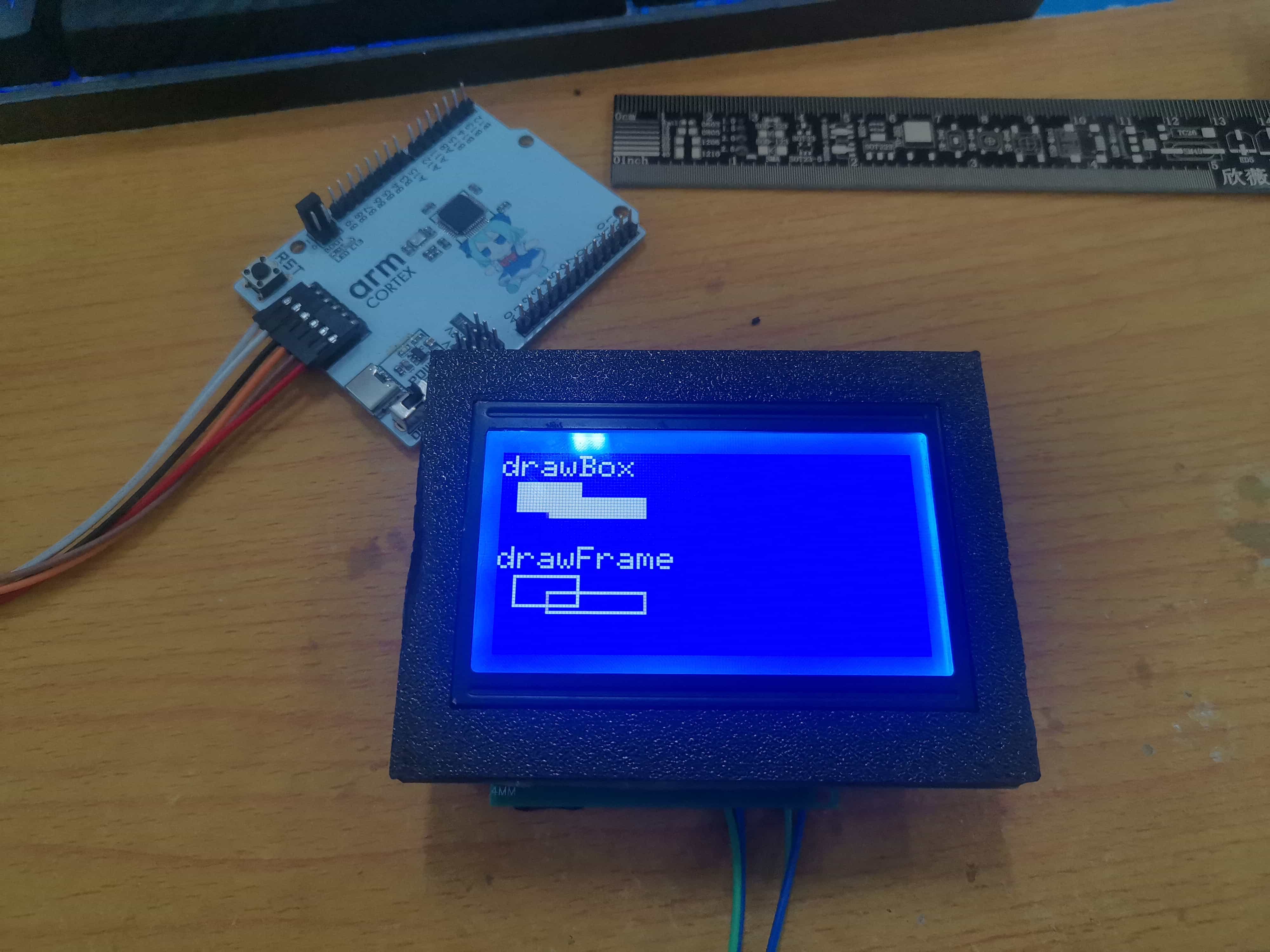
A standard version without color silkscreen printing is also available.
ArduinoUno.dxf
PDF_STM32F103C8T6 Uno Development Edition.zip
Altium_STM32F103C8T6 Uno Development Edition.zip
PADS_STM32F103C8T6 Uno Development Edition.zip
BOM_STM32F103C8T6 Uno Development Edition.xlsx
92364
CH569 USB3.2 Development Board
CH569 U3 development board and CH569 EVT Pro.
Based on CH569, USB3 development board.
[Commercial use prohibited]
1. The Type-C
project itself is based on the CH569 development board. One version was designed using color silkscreen printing, and another version was designed using the EVT form factor (unsoldered).
The step-down converter uses a TPS82130.
It is compatible with the CH569 timeline from WCH.
2. Project progress:
[2024.09.09]
[V1 version], release version
3. Image gallery.


PDF_CH569 USB3.2 Development Board.zip
Altium_CH569 USB3.2 Development Board.zip
PADS_CH569 USB3.2 Development Board.zip
BOM_CH569 USB3.2 Development Board.xlsx
92365
Electronic Calendar
Implement an electronic calendar using an ESP32-S3 module and a 4.2-inch e-ink screen.
Project Overview:
This project is an electronic calendar based on the ESP32-S3 microcontroller, featuring time and date display, temperature and humidity detection, and VOC monitoring.
Project Functions:
This design is an electronic calendar based on the ESP32-S3 microcontroller. In addition to its built-in e-ink screen display, it can also read temperature, humidity, time, and date data via a serial port connection to a serial debugging tool, and the time and date can be set via the serial port.
Project Parameters:
This design uses the AT24C02 memory chip, which can retain the set parameters even when the power is off;
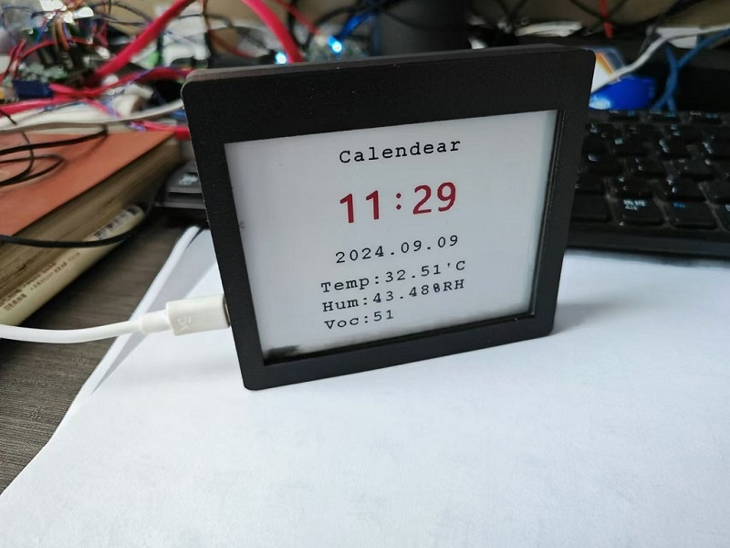
this design uses a 4.2-inch e-ink screen display, which displays the time, date, temperature, humidity, and VOC value from top to bottom;
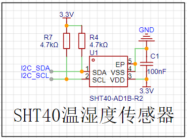
it selects the fully digital temperature and humidity sensor SHT40, which has a wide temperature measurement range and can meet general needs;
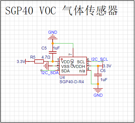
the SGP40 is a digital VOC (volatile organic compound) sensor, and combined with the VOC algorithm (part of the SGP40 VOC index driver package), the sensor signal can be directly used for indoor air quality assessment;
extended functions: SD card reader, ES8311 low-power mono audio codec, NS4150B audio power amplifier principle analysis (hardware description).
This project consists of the following parts: power supply, sensor, clock, e-ink screen display, main control, and voice recognition extension. This project mainly displays sensor and time information through an e-ink screen.
The power supply circuit uses a dual TYPE-C-16P
USB
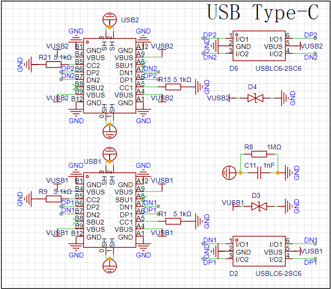
interface as the power supply interface. One uses the corresponding USB data pin to connect to the corresponding USB pin on S3 (USBD+ IO20), (USBD- IO19), allowing direct USB use for downloading and debugging without conversion to serial signals. 5.1K pull-down resistors are added to the CC1 and CC2 pins for easy identification and configuration by different hosts. The other uses a CH340K converter to convert to a serial signal, which can also be used for downloading and debugging communication.
The ideal diode

LM66100 has an on-resistance of 79mΩ at 5V and a maximum continuous current of 1.5A.
Ideal diodes can achieve power switching with minimal voltage drop and prevent reverse power flow.
The LDO circuit

uses RT9193 and ME6217 to power audio and other circuits respectively; the discrete LDOs further reduce the impact of power supply noise on the audio circuit. The SHT40
sensor measures relative humidity from 0 to 100% and temperature from -40°C to 125°C, achieving a humidity accuracy of ±1.8% and a temperature accuracy of ±0.2°C. The SGP40 , an upgraded version of the SGP30, is a VOC sensor featuring ultra-low power consumption (average power consumption as low as 2.6 mA / 3.3V), fast startup (<60S), and no calibration required. Most importantly, it incorporates a powerful VOC algorithm that converts the less intuitive VOC concentration into a VOC index that clearly indicates air quality. The RX8025T clock utilizes a built-in 32.768 kHz temperature-compensated crystal oscillator (DTCXO) for high timing accuracy. It provides a clock output, which, when connected to the ESP32-S3 pin, offers a more reliable low-frequency clock source. D1 enables backup battery power for continued clock operation after power failure. The e-ink screen driver is based on the relevant circuit design from MicroSnow Electronics and can be adjusted according to the specific screen type. The main control section uses the ESP32-S3-WROOM-1-N16R8 module, which can be directly connected to the pins, greatly reducing the design of peripheral circuits. The audio expansion section references the LCSC C3 development board and the Zhengdian Atom S3 development board; its functionality has not yet been verified. The software code example program is written in Arduino and implements the use of the e-ink screen, various sensors, SD card, clock, and serial port. Demonstration and content are attached. Important Notes: In PCB design, the analog ground of the audio section must be separated from the digital ground . The SHT40 is sensitive to heat sources; during layout, keep it as far away as possible from circuits that may generate heat, and avoid copper pours to reduce heat transfer. (See attached diagram.)


e-paper-calendear.zip
089feaea5f956c18f43ab6d0ef3f245b.mp4
PDF_Electronic Calendar.zip
Altium_electronic_calendar.zip
PADS_Electronic Calendar.zip
BOM_Electronic Calendar.xlsx
92366
ESP32 Weather Clock
After seeing so many people make weather clocks, and various vendors selling them, I finally decided to make one myself.
Why I Wanted to Make a Weather Clock:
Everyone wants a weather clock. It's something every ESP32 beginner wants to make
. For beginners, it's a great learning project.
I originally bought a weather clock component (non-color screen) on Taobao, but coincidentally, LCSC EDA launched this ESP32 design competition. The hardware components
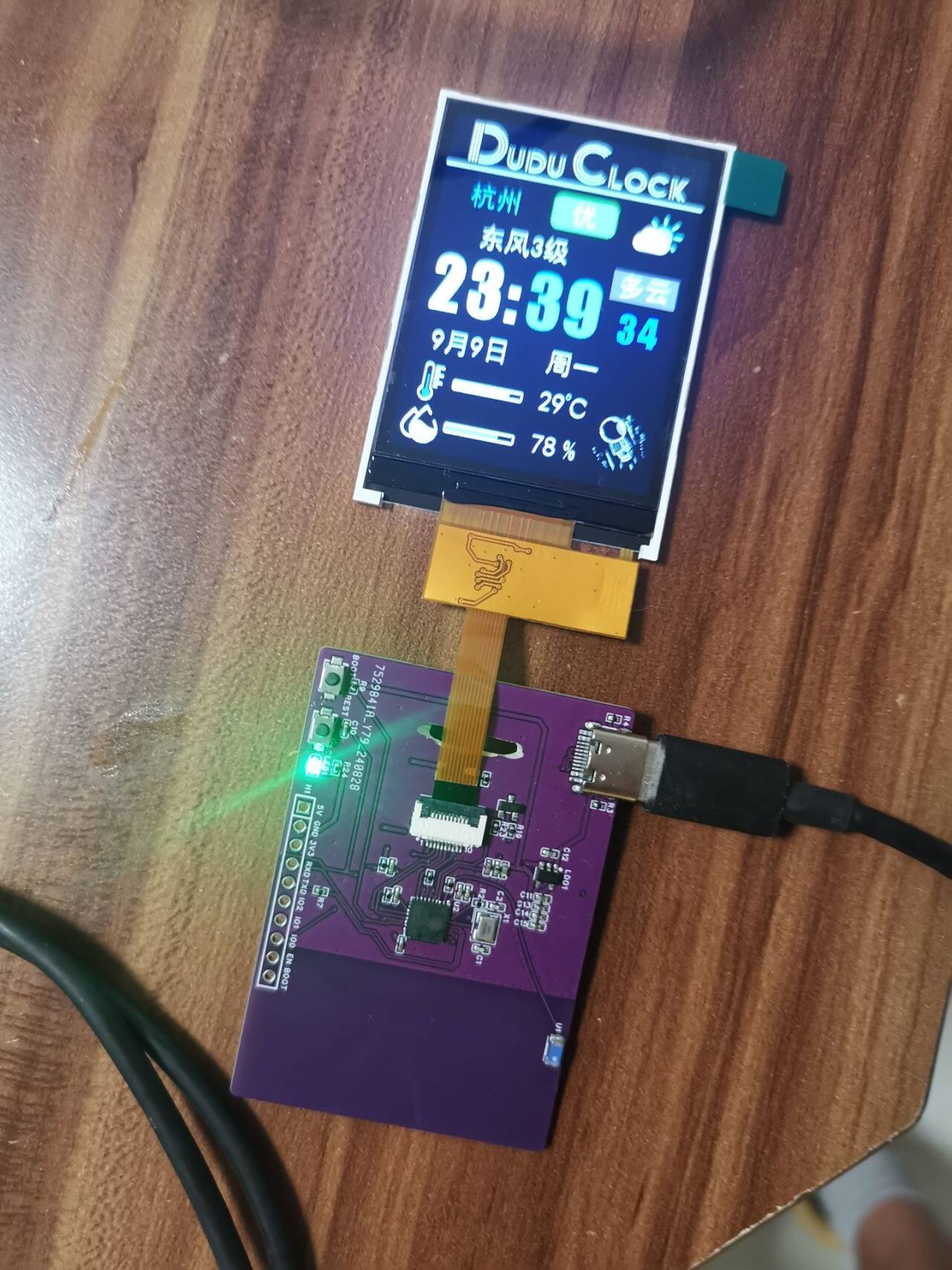
of the weather clock
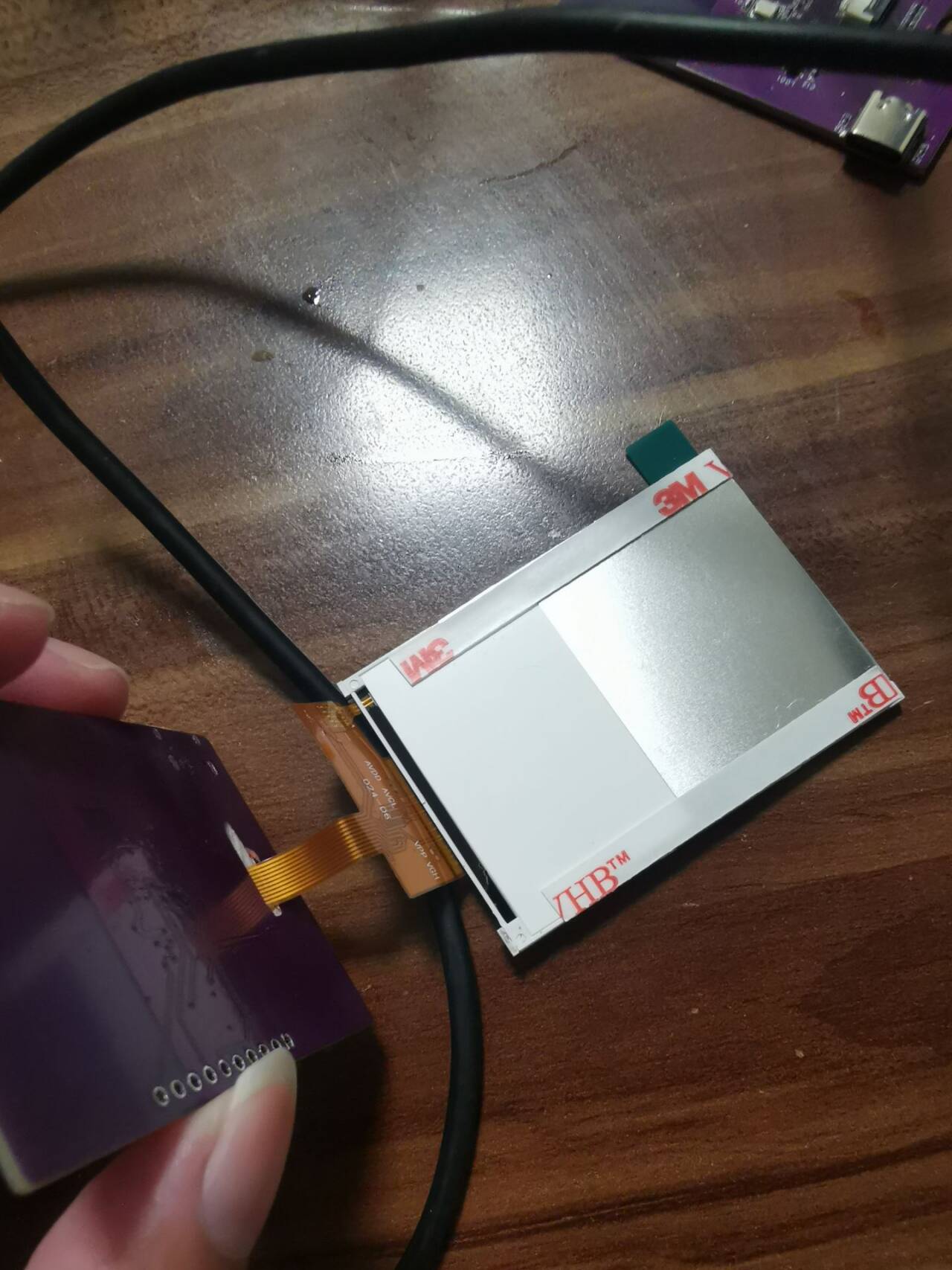
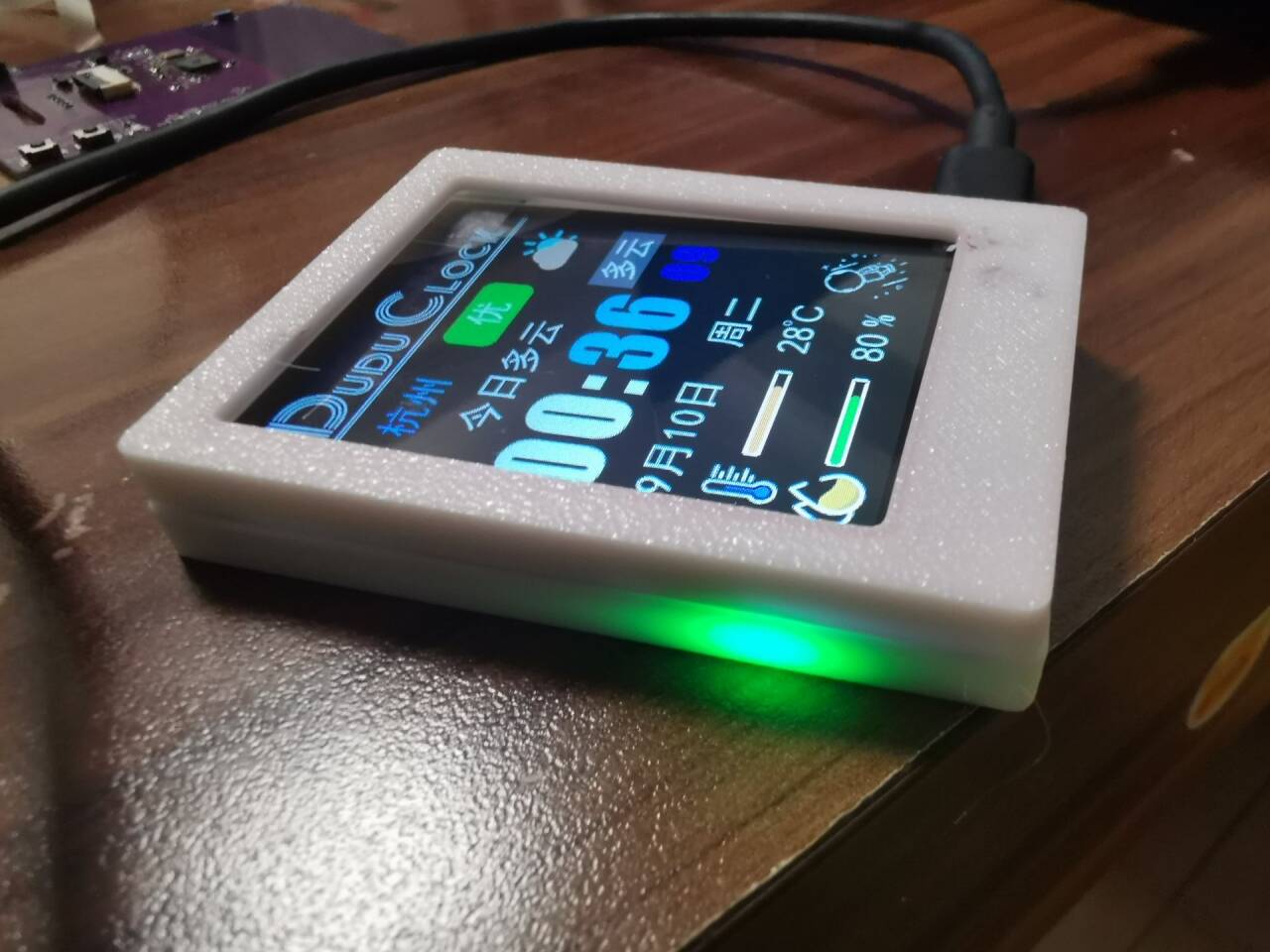
are very simple. The main parts are the ESP32 C3 main controller (with built-in 4MB Flash) and a 2.8-inch display
. For the software, I directly used the code from the DUDU weather clock. Partly because I encountered various problems that caused project delays, and partly because the DUDU weather clock was such a good project to learn from! (Haha) At the beginning of
the construction process
, I felt that designing the antenna for the ESP32 C3, if I were to run the wires myself, would require considering too many details such as impedance matching, which stumped me. So when someone told me I could use a ceramic antenna, I thought it would be a simple and straightforward solution. I just drew a board. Then someone else told me that the ceramic antenna also needed to consider the distance from the main controller, and the wiring had to be curved. Issues included drilling holes for grounding along the wires. The antenna also needed impedance considerations, requiring inductors and capacitors.
This led to a redesign of the board, which wasted time. Feeling pressed for time, I moved the antenna closer to the side, significantly reducing the distance, but I'm still not entirely satisfied; it's still a bit far from the main controller. Hopefully, the antenna will work (and ultimately it will). The
crystal oscillator part was problematic. The crystal's impact on the antenna needs to be considered. I referenced many projects, some using 24nH inductors, but I didn't have time to buy those. I used a 0-ohm inductor for now. Initially,
I was stuck on firmware flashing and getting it to power on. It took me a whole day. I had previously worked with ESP32 development boards with pre-installed firmware. So, those boards connected directly to the computer, and the COM port in Device Manager remained stable. But mine wasn't; it kept appearing and disappearing. My first thought was that the chip was constantly rebooting, stuck in an infinite reboot loop. I also tried pressing BOOT and then RESET to enter flashing mode, but perhaps my technique wasn't correct, and it didn't work. This led me to suspect a problem with my board design, a faulty main controller solder joint, or other component issues. I spent half the day desoldering, resoldering, and repairing the board (which was actually fine). It wasn't until the next day when a member in the group told me that the blank chip itself would continuously restart that I realized I might have done something wrong.
Finally, I discovered that pressing the BOOT button while powering on (or RESET) worked perfectly!
Because of the event delay, I hastily used the DUDU clock code. I directly compiled and input the firmware,
modified the pins, turned on the backlight, registered an account and key for a weather website, compiled and burned the firmware, and configured Wi-Fi.
Everything went smoothly!
There are a few things to note during the compilation process:
You need to manually obtain the key from the weather website in common.h and fill it in.
You need to install the following libraries:
TFT_eSPI (you need to put User_Setup.h in),
ArduinoJson,
OneButton,
TaskScheduler
, and ArduinoZlib (downloaded from GitHub, extract to the library directory).
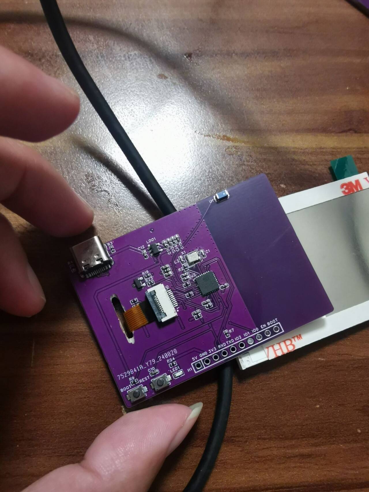
Hardware physical components.


QQ Video 20240910000528.mp4
DuduClock 2.0 source code package (2.8-inch 10P) ST7789.zip
ArduinoZlib-main.zip
PDF_ESP32 Weather Clock.zip
Altium_ESP32 Weather Clock.zip
PADS_ESP32 Weather Clock.zip
BOM_ESP32 Weather Clock.xlsx
92367
ESP32-Vision Module
A simple TOF laser ranging and vision implementation
Project Introduction:
A simple TOF laser ranging and vision implementation
project. Functionality
: Vision ranging is currently not implemented.
Software code: `
from utils.cam import init_cam, cam_capture
from utils.wifi import enable_wifi
from utils.light import light
from utils.socket import Socket_data
from utils.task import Task
from libs.data import Data
import utime
import _thread
import ujson
import ubinascii
import camera
def main():
try:
enable_wifi()
s = Socket_data()
init_cam()
while True:
cam_buf = camera.capture()
# temp, humidity = dht22()
# distance = measure()
encoded_cam_buf = ubinascii.b2a_base64(cam_buf)
# print(encoded_cam_buf)
data = Data(
cam_buf=encoded_cam_buf,
temp=0,
humidity=0,
distance=0,
light=light(),
)
json_data =` ujson.dumps(data.__dict__)
s.send_json_data(data=json_data.encode('utf-8'))
# print(json_data)
# s.send_data(data=data)
except Exception as e:
print(f"err: {e}")
main()
The actual image

effect is displayed
. The OV5640 frame rate is impressive.
QQ2024910-75416.mp4
cam.zip
PDF_esp32-VisionModule.zip
Altium_esp32-VisionModule.zip
PADS_esp32-VisionModule.zip
BOM_esp32-VisionModule.xlsx
92368
ESP32 IoT Mini TV
This system, based on the ESP32-S3-WROOM-1-N16R8 module, monitors formaldehyde, carbon dioxide, TVOC, PM0.3~PM10, as well as temperature and humidity, and integrates a 2.8-inch capacitive touchscreen.
1. Hardware Design
1.1 Core Board Selection:
ESP32-S3-WROOM-1-N16R8: Serves as the main controller, responsible for data processing, wireless communication, and power management.
1.2 Sensor Selection
: TVOC sensor (e.g., CCS811);
Temperature and humidity sensor (e.g., DHT40).
1.3 Display:
2.8-inch capacitive touchscreen: Connected via SPI or I2C interface .
1.4 Power Supply System
: Type-C interface for direct power supply.
1.5 Circuit Design
: Design the PCB board, allocate I/O ports appropriately, and ensure correct connection of each sensor, display, power management module, etc.
Pay special attention to the ESP32's GPIO allocation to avoid conflicts.
2. Software Design
2.1 ESP32 Firmware Development
Environment Setup: Develop using ESP-IDF or Arduino IDE.
Sensor Drivers: Write or integrate driver code for each sensor to read data.
PDF_ESP32 IoT Mini TV.zip
Altium_ESP32 IoT Mini TV.zip
PADS_ESP32 IoT Mini TV.zip
BOM_ESP32 IoT Mini TV.xlsx
92369
Color screen printing - Immortal Totem
The immortal totem made using a color silkscreened coupon, with its gilded finish, might actually help you transcend life and death (just kidding).
The immortal totem made using a color silkscreened coupon, with a gold-plated finish, may actually help you transcend life and death (please do not attempt this).


The top hole is 1.4mm high and 3mm wide for attaching a keychain.

PDF_Color Silkscreen - Immortal Totem.zip
Altium_Color Silkscreen-Immortal Totem.zip
PADS_Color Silkscreen - Immortal Totem.zip
PDF_Color Silkscreen - Immortal Totem.zip
Altium_Color Silkscreen-Immortal Totem.zip
PADS_Color Silkscreen - Immortal Totem.zip
92370
electronic


 京公网安备 11010802033920号

 177-710-5-25CS4J1-24BNN


