zTR4c20

CH549G_DAP Downloader

 
Overview
CH549G_DAP_Debugger
I. Introduction


The system uses a 3.3V power supply;


the MODE button is used to switch modes (press and hold MODE while powering on to switch): ARM microcontroller program download (DAP_MODE: LED_RUN is always on when idle), RISC-V microcontroller program download (RISC-DAP_MODE: DAP light is off when idle);


the BOOT button is used for program burning (press and hold BOOT while powering on to download the program);


II. Firmware Burning
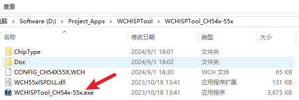
2.1


Install the burning software WCHISPTool_Setup.exe, locate the CH54x folder in the installation directory, and start the burning software;


2.2 Download Mode


Press and hold the BOOT button while powering on;


2.3 Download Firmware


Confirm the following options, click Download, and burn the DAP firmware;


Firmware burning is complete, as shown in the figure below;


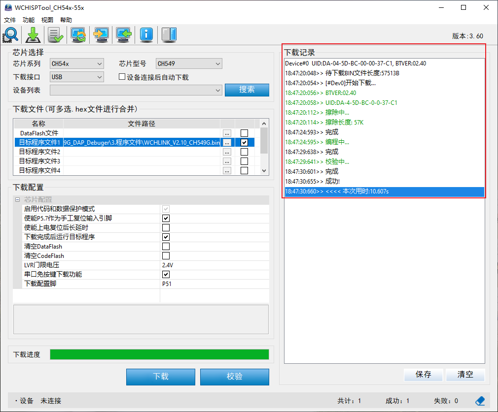
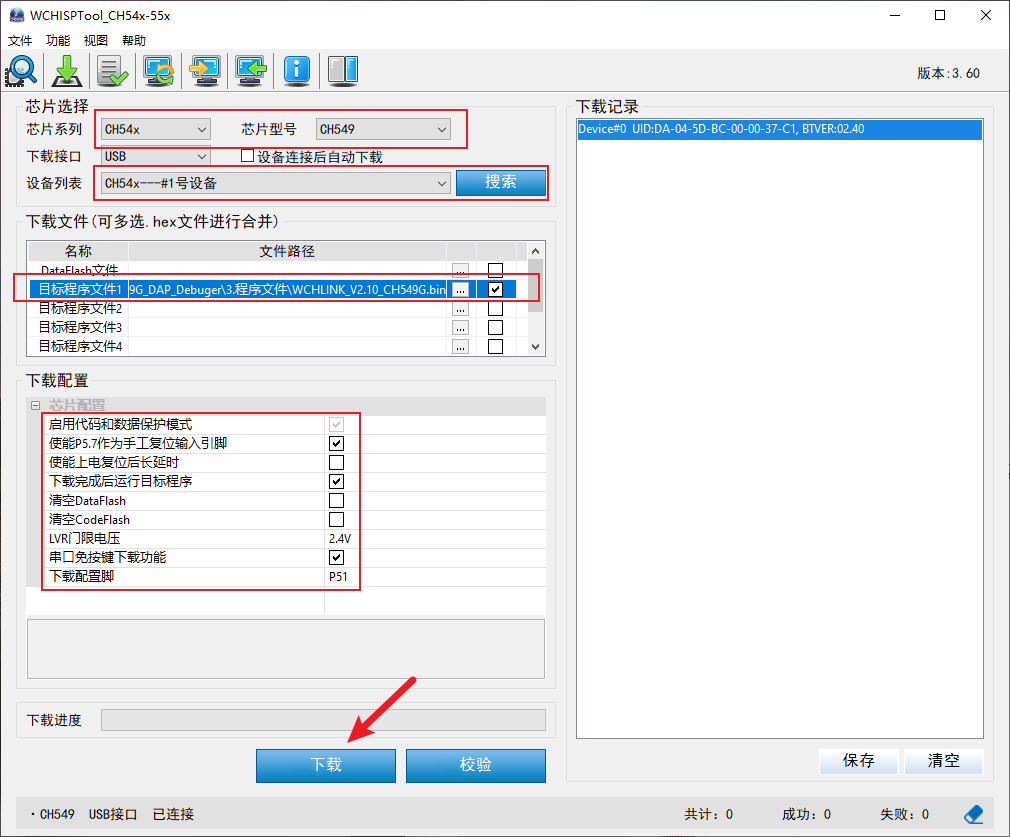
III. Debugging and Use
3.1 DAP Program Download
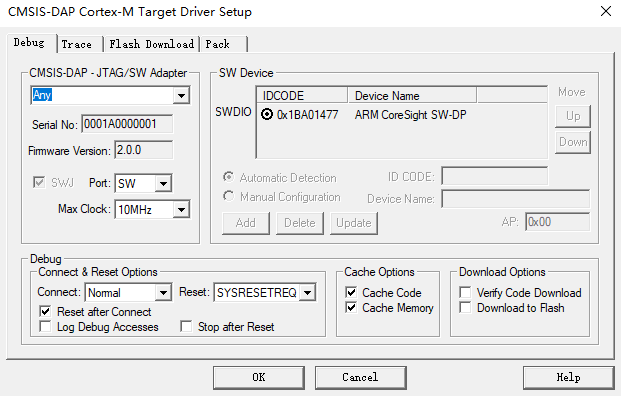
3.2 USB to Serial Port
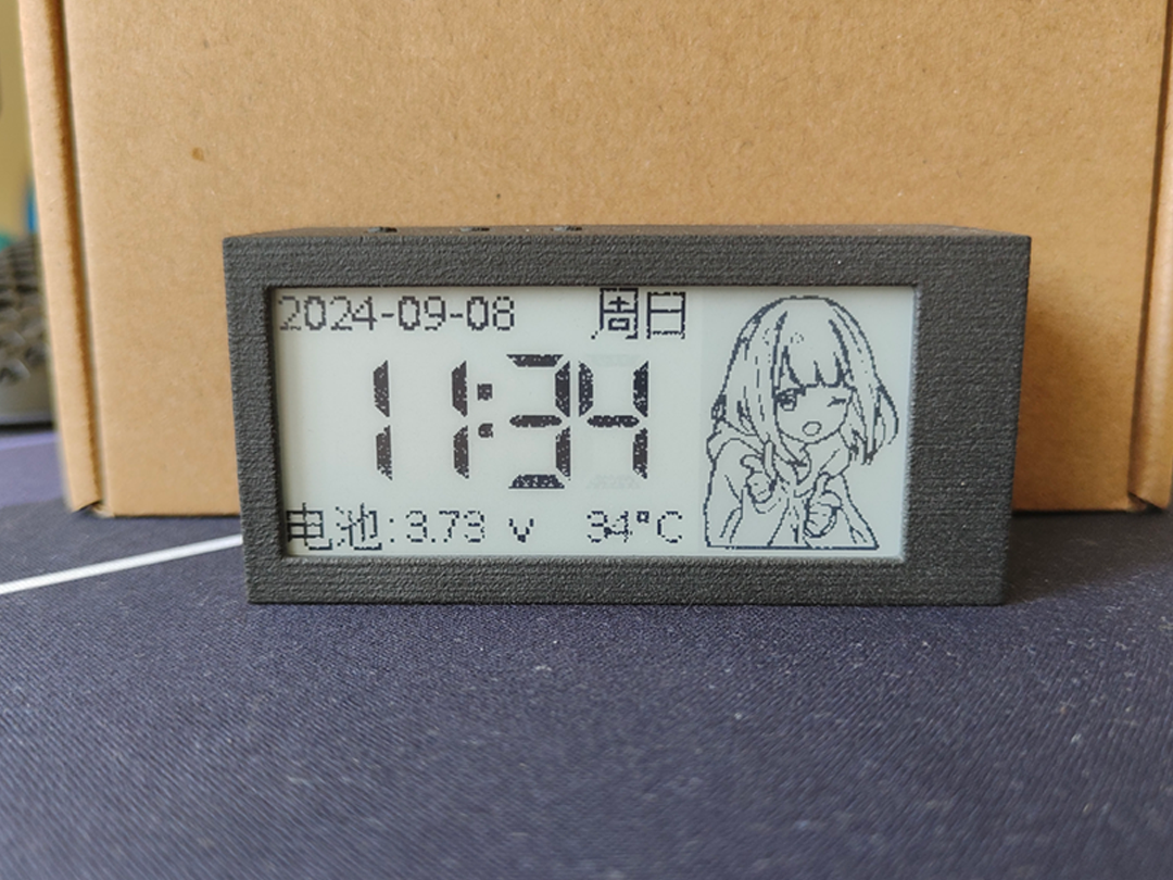
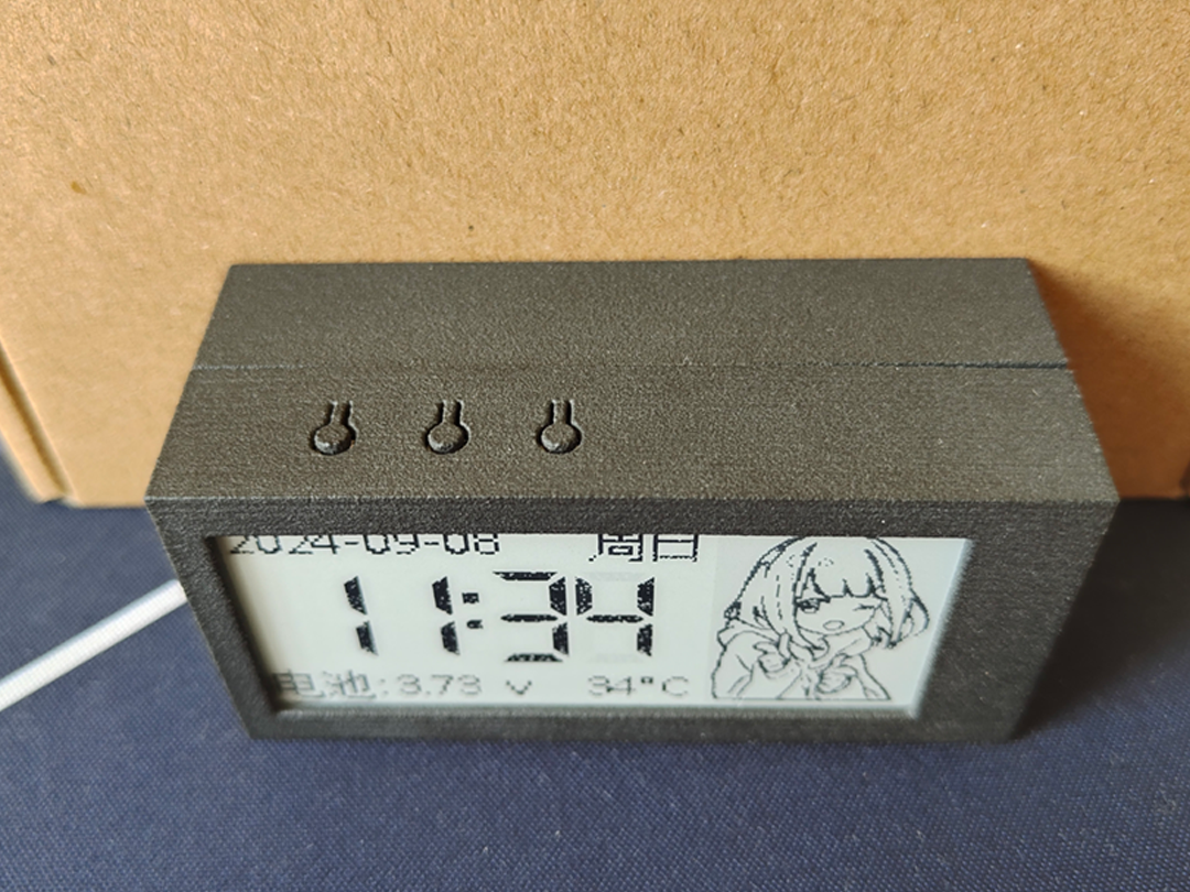
In addition to being used as a DAP downloader, it can also be used as a USB to serial port tool.
2024_09_01_CH549G_DAP_Debuger.zip
92402
ESP32 IoT plug-in board
ESP32-based remote control of power strips
Project Overview:
This project is a power strip control system based on the ESP32-WROOM32-32 microcontroller. It primarily addresses the operational status of different appliances on the same power strip, offering low cost and low power consumption.
Project Functions:
This project, based on the ESP32-WROOM32-32 microcontroller, includes remote control, status feedback (time and date), signal strength monitoring, local remote control, and one-button remote control pairing.
Project Parameters:
Remote control utilizes MQTT communication, ensuring stability and reliability.
Local remote control employs a Hummingbird Wireless 433M wireless module, offering ease of use.
Principle Analysis (Hardware Description):
The 220V AC power is transformed using an ACDC converter, outputting 5V DC to power the microcontroller and other devices. The ESP32 microcontroller then drives an L9110S driver chip to power a magnetic latching relay. The magnetic latching relay is only energized during switching, reducing power consumption and coil heating. Simultaneously, the wireless module communicates with the microcontroller, enabling the microcontroller to perform corresponding actions.
The software code
is in the attachment.
Important notes:
220V power supply is dangerous; please proceed with caution.
Assembly process:
Pictures of the assembled product are in the attachment.
Actual product
photos are in the attachment.
WeChat_20240907213353.mp4
WeChat image_20240907213341.jpg
WeChat image_20240907213400.jpg
WeChat image_20240907213404.jpg
WeChat image_20240907213348.jpg
PDF_ESP32 IoT plugboard.zip
Altium_ESP32 IoT plug-in.zip
PADS_ESP32 IoT plug-in board.zip
BOM_ESP32 IoT Panel.xlsx
92404
Esp32c3 Servo Drive Board
5-channel servo motor driver based on ESP32C3
Project Overview:
This project is a five-channel servo drive board based on the ESP32C3-Mini.
Project Function:
It can simultaneously control five PWM servos.
Project Parameters


: Power Supply
: Input voltage 16V (2-4s battery);
Output voltage adjustable, maximum output current up to 10A;
Output voltage adjustment is possible via resistors on the power board.


Other Onboard Modules:
One I2C gyroscope and accelerometer;
One 16*42 mini OLED screen;
Three buttons with pull-down circuitry.


Core Board: The core board itself has a built-in Type-C interface for downloading;
An I2C interface is located on the back of the board for expansion.
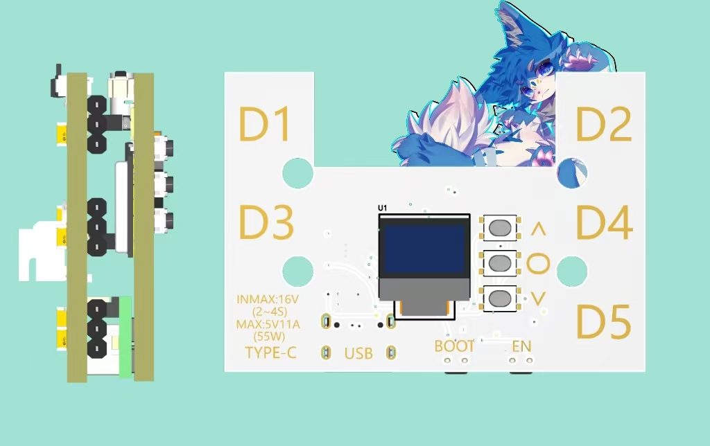
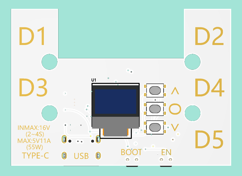
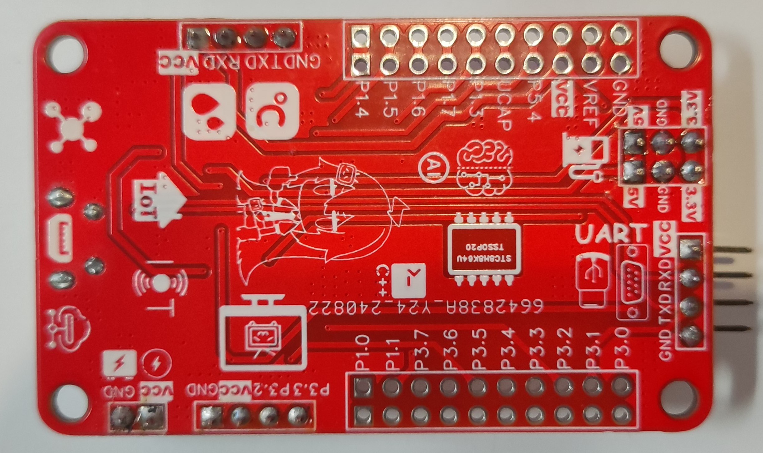
Principle Analysis: (Hardware Description)
This project consists of two circuit boards:
a core board and a power board .
They are connected vertically via headers and pin headers.
A 16V voltage is
stepped down to 5V by the power board, then
back down to 3.3V by the core board via headers and pin headers
to supply the chips. The chips send PWM signals to the power board below
via headers and pin headers on the core board, which then drives five servos. Note: Because chip packaging and soldering are relatively difficult, it is recommended to use a soldering station. There are five 100µF capacitors on the back, which can be soldered or left unsoldered. Assembly Process : Well, there's not much to say; just assemble them after soldering. [ Image of the actual product]


PDF_Esp32c3 Servo Driver Board.zip
Altium_Esp32c3 Servo Driver Board.zip
PADS_Esp32c3 Servo Driver Board.zip
BOM_Esp32c3 Servo Driver Board.xlsx
92405
ESP32C3 Desktop Clock and Night Light
The front is a clock, and the back is a night light.
Project Overview:
This project uses the ESP32C3 chip and is developed based on Arduino. It features a clock and night light functions. The front of
the screen

is a 2.9-inch e-ink clock displaying year, month, day, weekday, time, battery voltage, internal temperature, and a custom image.
The back is a light board with eight 0.2W LEDs in series and two in parallel, providing a maximum power of 3.2W.
The three buttons on the back, from left to right, are: LED brightness adjustment, manual NTP time update, and software restart. The dimming function has three fixed levels: 20%, 50%, and 100%. The other two buttons are for preventing accidental touches; they require a quick double press to activate.
The Type-C port on the left is for charging and communication. Charging is 5V 1A by default, and the ESP32C3 can be debugged through this interface.

Project Parameters:

This project uses a WFT0290CZ10 e-ink screen with a resolution of 296*128.
The e-ink driver uses the EPaperDrive library and a hardware SPI driver; theoretically, any screen in the EPaperDrive library can be used.
The night light section uses the LGS63032 as a constant current boost chip, sharing a 4kHz PWM with the buzzer for dimming. A buzzing sound at low duty cycles is normal.
The battery voltage sampling section uses the internal calibration parameters of the ESP32C3, with acceptable accuracy.
Temperature sampling uses a 10K 3950B NTC thermistor, mainly used to detect the temperature of the light board; excessively high temperatures will reduce the LED's duty cycle.
The charging section uses the classic 4056 chip, consuming only a few µA of current when not charging.

Principle Analysis (Hardware Description):
This project consists of the following parts: main control unit, LED lighting unit, screen unit, power supply unit, and battery charging/discharging unit. This project mainly obtains NTP time through the network and synchronizes it with the RTC clock, periodically updating the screen display content, and then combining this with button presses to complete the corresponding functions.
I won't go into detail about the main control unit, screen, and power supply unit; I'm a beginner and don't understand them either~( ̄▽ ̄)~.
Type-C Circuit:
A TYPE-C-16P interface is used as the power supply interface. The corresponding USB data pins are connected to the corresponding USB pins on the S3 (USBDN IO18, USBDP IO19), allowing direct USB download and debugging without conversion to serial signals. 5.1K pull-down resistors are added to the CC1 and CC2 pins for easy identification and configuration by different hosts.
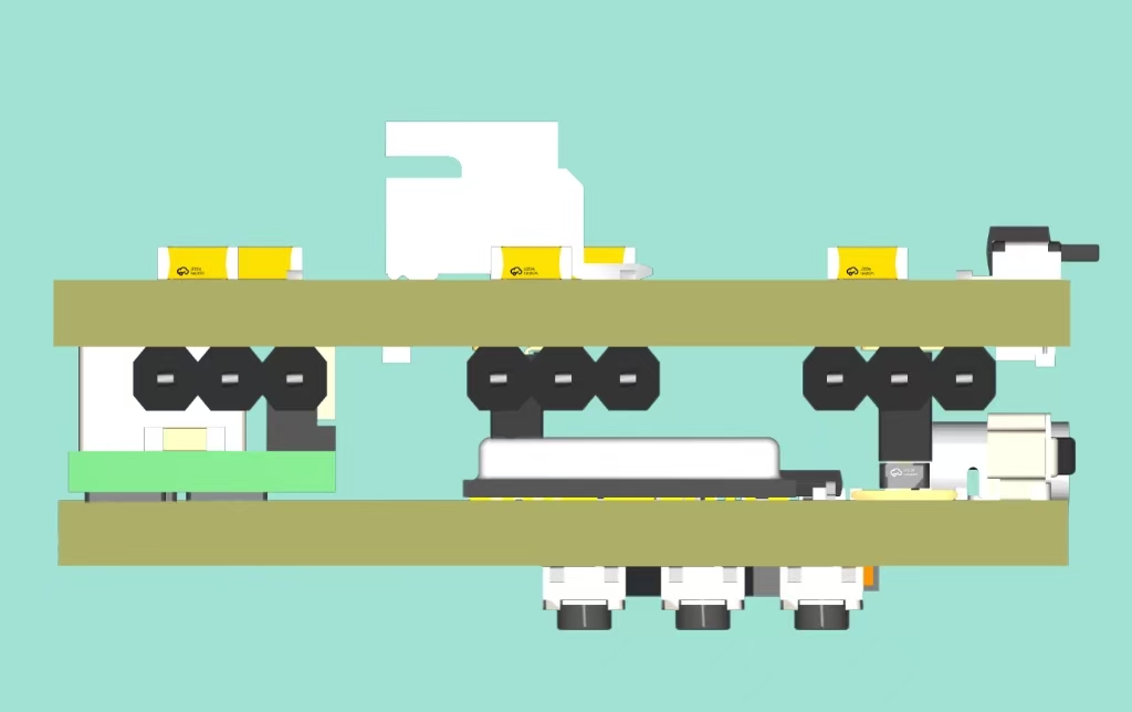
LED Lighting Circuit:
An LGS63032 is used as the constant current boost controller. The constant current depends on the value of R25 (I=0.2V/1.6Ω). It is recommended to design the lamp board according to the parameters in the datasheet to achieve the highest conversion efficiency. When redesigning, pay attention to the rated current of the inductor. Testing shows that 3.2W of power is suitable for the lamp board.
Battery Charging/Discharging Section:
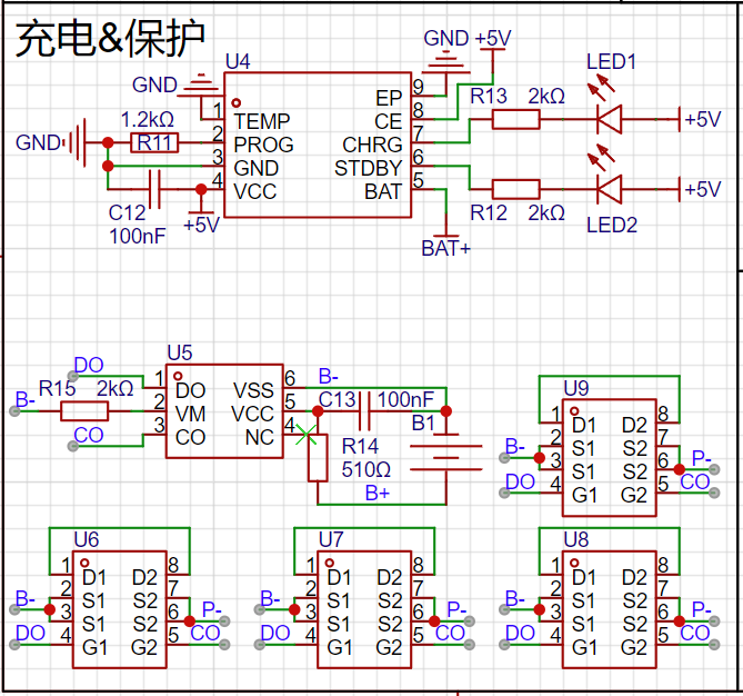
The battery charging uses the classic 4056 chip. The datasheet indicates that the chip's power consumption is below 10uA, and it can reach as low as 2uA when not plugged in. The charging current in the diagram is set to 1A. When purchasing 18650 batteries, pay special attention to the battery charging current!
The lithium battery protection uses DW01+8205 MOSFETs, which is a cost-effective and mature solution. Only four 8205 MOSFETs are needed; the two extra ones on the PCB can be left unsoldered.
Software code:
//External libraries used only: EPaperDrive library
//arduino 2.3.2
//ESP32 3.0.3
The following are Arduino settings; please ensure all settings are consistent.


Appearance:
Version

V1.0.0 has not yet implemented low-power processing; a 2600mAh battery will last approximately one week.
VID_20240908153434.mp4
Component 1. step
Component 2. step
esp32c3-desktop-clock-with-night.zip
Compiled binary file.zip
PDF_ESP32C3 Desktop Clock and Night Light.zip
Altium_ESP32C3 Desktop Clock and Night Light.zip
PADS_ESP32C3 Desktop Clock and Night Light.zip
BOM_ESP32C3 Desktop Clock and Night Light.xlsx
92407
ad835 module
The AD835 multiplier module allows for positive or negative bias on the Y-channel by adjusting jumpers and potentiometers.
This is the multiplier module from this year's electronics design competition. The AM modulation depth can be adjusted by applying a negative voltage to pin Y2. The modulator was not drawn according to the manual. If the modulator design is done according to the manual, the carrier amplitude requirement will be very large when the modulation depth is large, which is not convenient for adjustment.
PDF_ad835 module.zip
Altium_ad835 module.zip
PADS_ad835 module.zip
BOM_ad835 module.xlsx
92409
esp32_temperature and humidity station
A simple ESP32 thermometer and hygrometer
Project Overview:
This project is a thermometer and hygrometer based on the ESP32-C3 microcontroller. It can detect the temperature and humidity in a room and is directly connected to HA (Home Assistant). Because we want it to be very discreet, the light will only turn on when it is charging and will not be lit in other scenarios.
Project Functionality:
This design uses esphome firmware, so you basically don't need to write any code to drive the sensor. You only need to configure the esphome scripts, and it will automatically add the sensor to the HA.
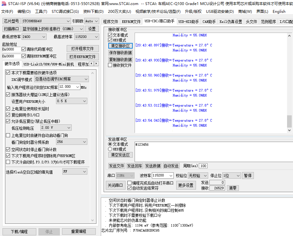
My configuration is shown in the image. I originally planned to add a BH1750, but esphome couldn't initialize the sensor. This is probably due to my hardware design or soldering issues. This device is very small, and you can hardly see the pin soldering. After several attempts, I gave up.
Project Parameters

: This design uses the ESP32-C3-WROOM-02-N4 module. I happened to get 10 of them for free during a previous Espressif promotion, so I used them.
This design uses the Guangzhou Aosong AHT20 temperature and humidity sensor. This device communicates via the IIC bus. The humidity sensor has an accuracy of ±2%, and the temperature sensor has an accuracy of ±0.3℃, which is very high.
Battery management uses the LGS5600C, a dischargeable battery management chip.

Principle Analysis (Hardware Description):
This project consists of the following parts: power supply, sensor, main control, and battery management.
The power supply section
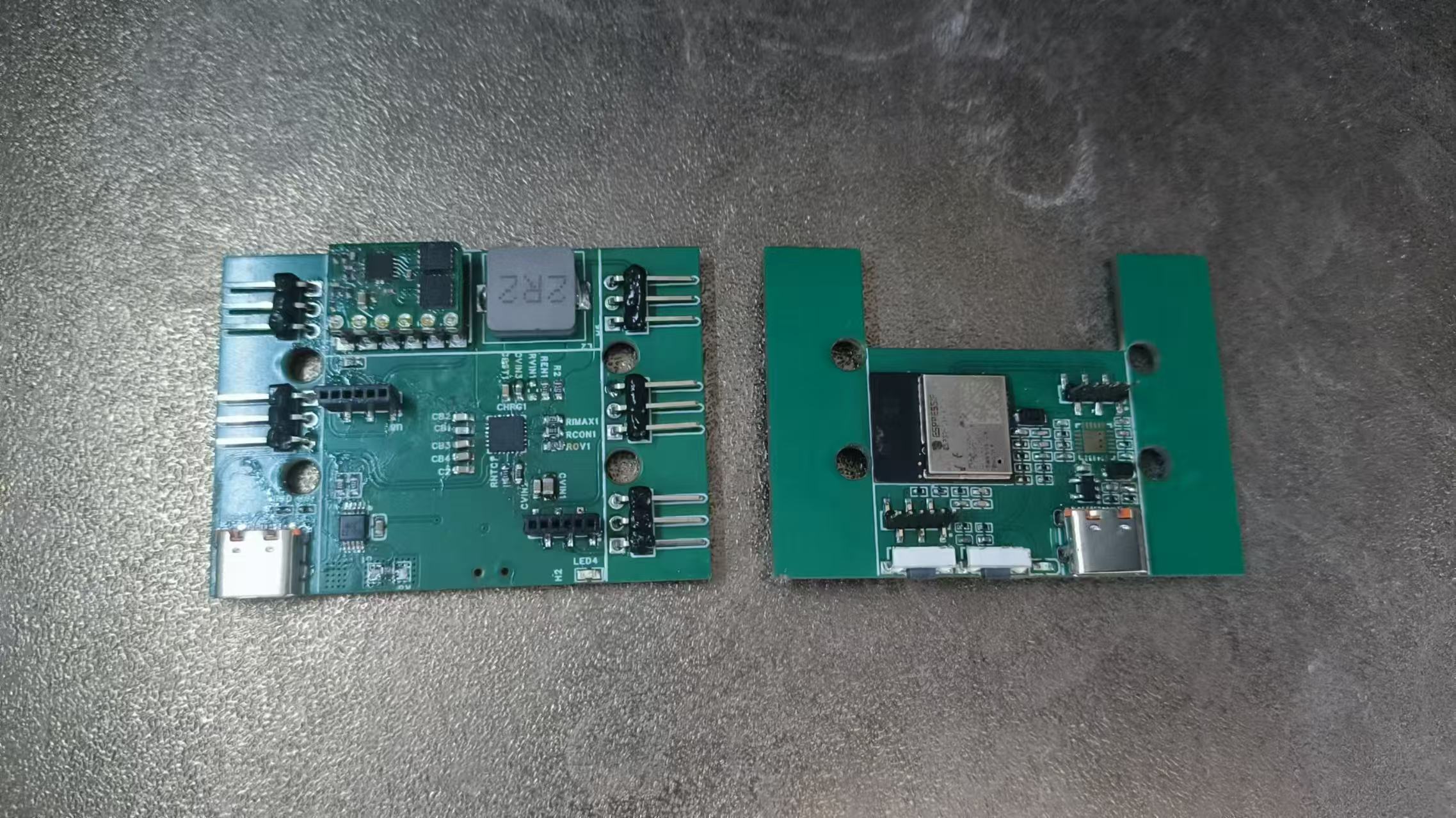
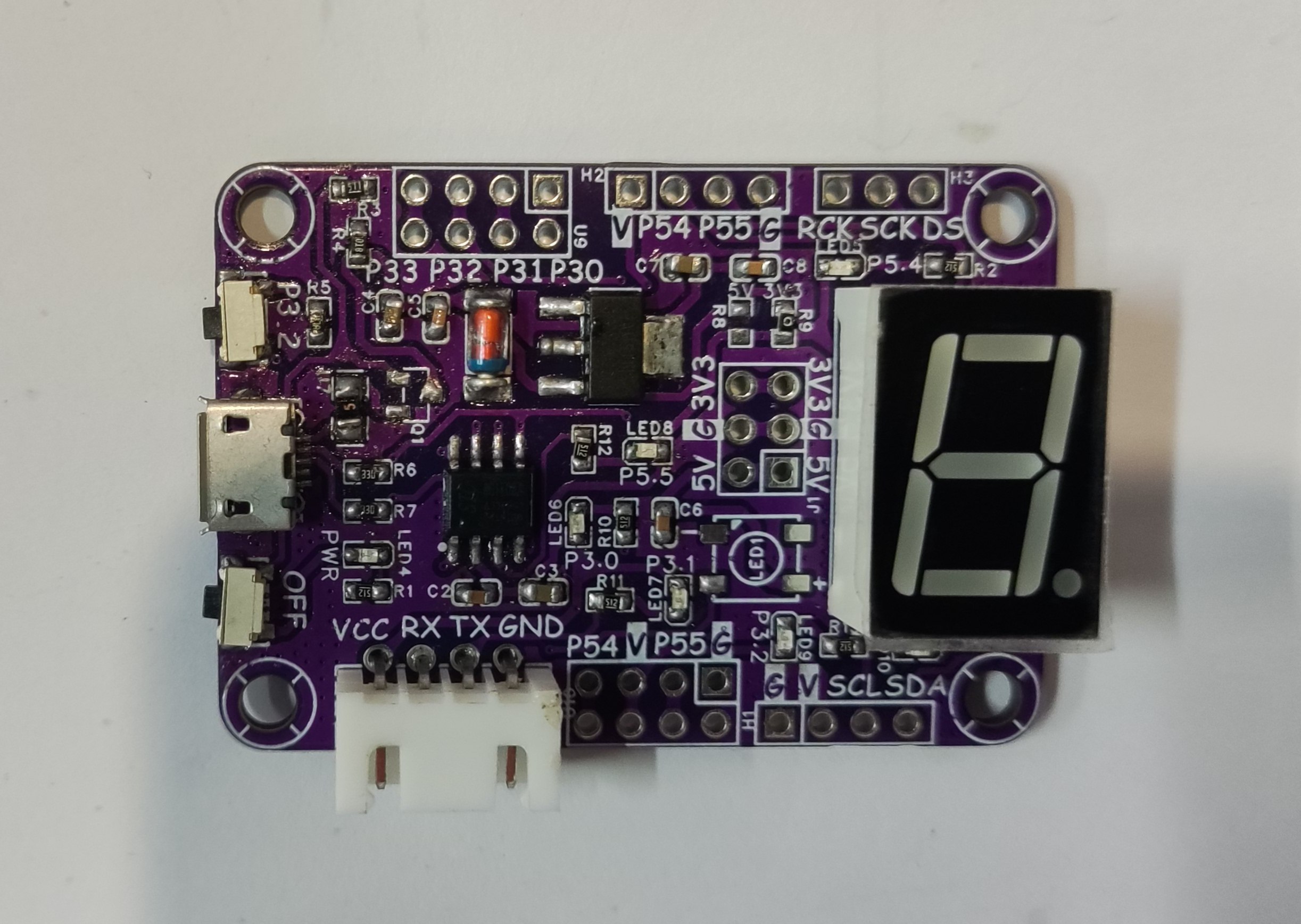
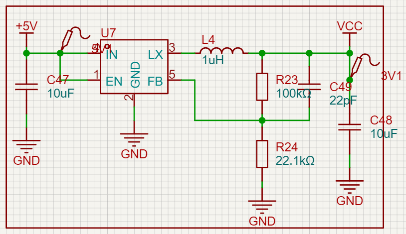
is shown in the figure. This is a DC-DC step-down circuit using the SY8089 chip. This chip is inexpensive, has a wide input voltage range, and can output up to 2A. Its peripheral circuit is also very simple, requiring only one inductor, three capacitors, and two resistors. One of the resistors is used to configure the output voltage. I have set it to 3.3V output. However, a drawback is that this chip is a step-down chip, so the output voltage will also decrease when the input voltage is low.
The battery
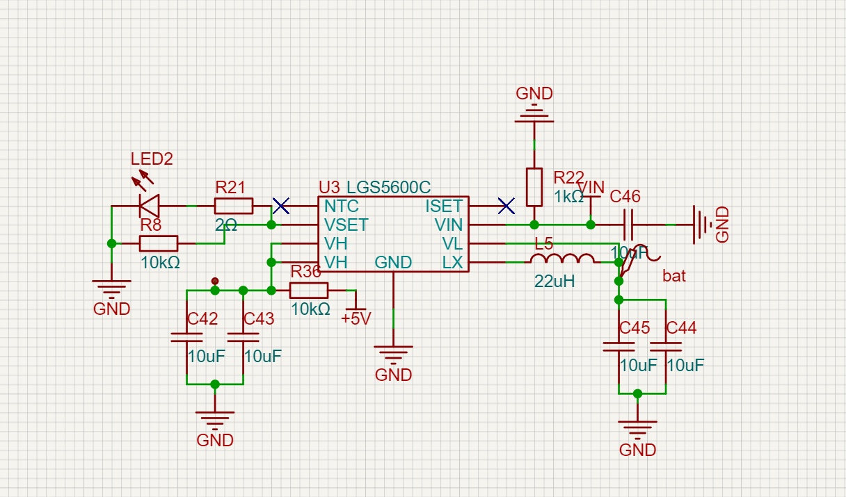
management chip used is LGS5600C, but the problem I encountered is that the chip outputs 5V normally when the battery is charging, but there is no output when the battery is not in use, only about 0.2V. I don't know why yet. I need to contact the manufacturer's technical support when I have time. The sensor
part
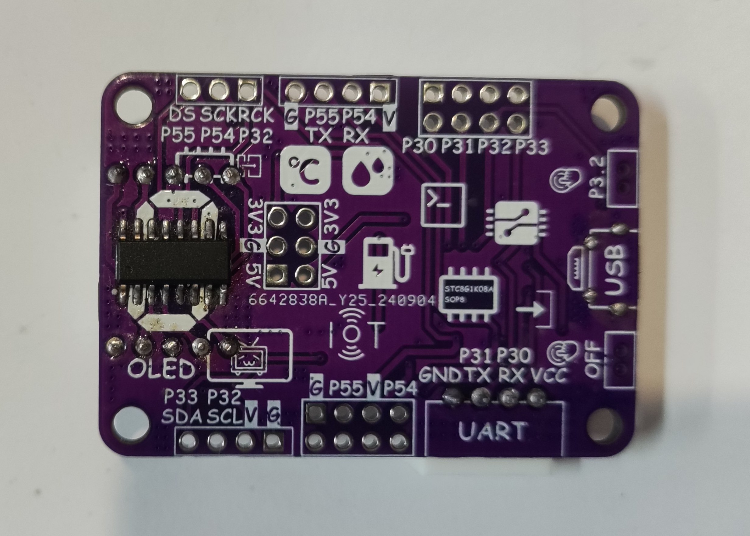
is relatively simple; just build the basic peripheral circuit according to the manual. However, one thing to note is that when laying out the temperature and humidity sensors, you should cut grooves around them as much as possible to avoid interference from the MCU or other heat-generating devices. My design was a bit rushed, so please don't imitate it.
The official manual also describes it this way. The main
control
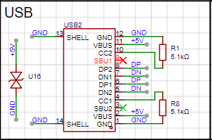
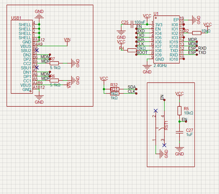
part is relatively simple because the ESP32-C3 has USB download functionality, which saves one CH340K chip (another day of cost savings). The peripheral circuit of the chip is also built according to the minimum system given in the datasheet.
To reduce the difficulty of hardware soldering, the capacitors and resistors used are all 0603 packages.
Software code
: I2C: #Configure IIC bus
sda: GPIO6 #sda data line
scl: GPIO7 #scl clock line
scan: true # Whether to enable IIC address scanning
id: bus_a # Bus ID
sensor: # Sensor-
platform: aht10 # Sensor type
variant: AHT20 # Sensor model
temperature: # Temperature setting
name: "Temperature" # Temperature name (entity name displayed in HA)
humidity: # Humidity setting
name: "Humidity" # Humidity name (entity name displayed in HA)
update_interval: 1s # Update time
The code part is just a YAML configuration, after all, esphome has provided the driver, so why not use it? Note: The PCB of the temperature and humidity sensor needs to be grooved around the perimeter. Assembly Process : The casing is still under design and printing has not yet started. Battery management is also not yet finalized, so it will take some time before
the main assembly is complete. Physical Image


PDF_esp32_Temperature and Humidity Site.zip
Altium_esp32_temperature and humidity site.zip
PADS_esp32_temperature and humidity site.zip
BOM_esp32_temperature and humidity site.xlsx
92410
STM32 remote control
This is a 2.4GHz remote control based on STM32, written using the HAL library. The board can be obtained free of charge through a quick pairing service.
This is a 2.4GHz remote control based on the STM32F103C8T6. Some hardware components are referenced from the work at https://oshwhub.com/bukaiyuan/ESP32-hang-mu-yao-kong-qi. The board size is 10cm*15cm. Free prototyping is available at Jiepei. The charging module supports 18W fast charging. The code can be found in the compressed file or viewed at 442827947/diy_rc (github.com).
diy_rc.rar
diy_rc_parts list.xlsx
PDF_stm32 Remote Control.zip
Altium_stm32 Remote Control.zip
PADS_stm32 Remote Control.zip
BOM_stm32 Remote Control.xlsx
92412
Scalable Thermohygrometer Design Based on STC8H8K64U-TSSOP20
This is an expandable temperature and humidity meter design based on the STC8H8K64U-TSSOP20, with all chip I/O ports brought out, including interfaces for DHT series temperature and humidity sensors and IIC OLED display interfaces.
This is a scalable temperature and humidity meter design based on the STC8H8K64U-TSSOP20 chip, with all chip pins exposed for easy further development. It provides serial port test code for the DHT11 temperature and humidity sensor, and a 4-pin OLED display interface with IIC communication protocol for engineering temperature and humidity display and debugging. The onboard WS2812B tri-color LEDs can be used to read the DHT11 temperature and humidity sensor's OLED display temperature and humidity
 
via serial communication , enabling RGB color lighting and breathing light effects.
 

DHT11_UART.c
PDF_Scalable Thermohygrometer Design Based on STC8H8K64U-TSSOP20.zip
Altium-based scalable thermometer and hygrometer design based on STC8H8K64U-TSSOP20.zip
PADS_Scalable Thermohygrometer Design Based on STC8H8K64U-TSSOP20.zip
BOM_Design of a Scalable Thermohygrometer Based on STC8H8K64U-TSSOP20.xlsx
92413
STC8G1K08A-SOP8 Development Board
The STC8G1K08A-SOP8 development board enables onboard LED, WS2812, and single-digit LED display illumination; one-wire DS18B20 temperature sensor data reading; OLED screen IIC communication display; DHT11 temperature and humidity sensor interface; and USB program download.
The STC8G1K08A-SOP8 development board enables onboard LED, WS2812, and single-digit LED display illumination; one-wire DS18B20 temperature sensor data reading; PWM breathing light; OLED screen IIC communication display; DHT11 temperature and humidity sensor interface; USB program download; and serial port download functions. (
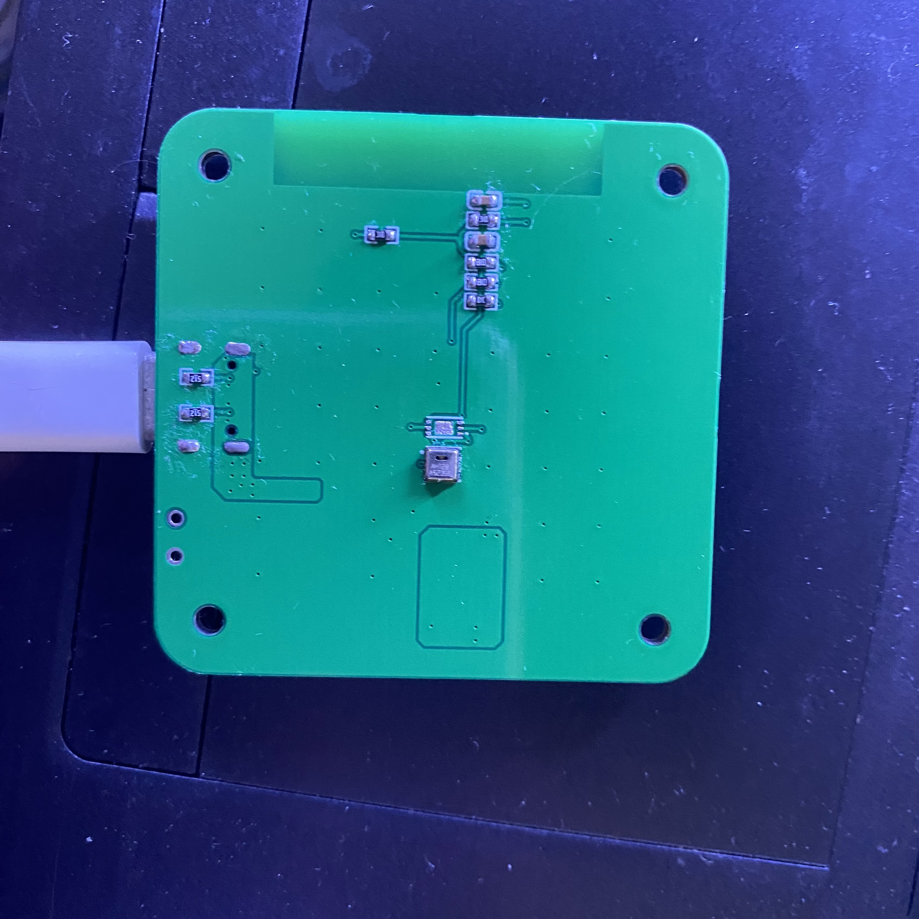
Flashing light program effect shown .)
LED_Blink.c
PDF_STC8G1K08A-SOP8 Development Board.zip
Altium_STC8G1K08A-SOP8 development board.zip
PADS_STC8G1K08A-SOP8 development board.zip
BOM_STC8G1K08A-SOP8 Development Board.xlsx
92414
electronic
参考设计图片
×
 
 
Search Datasheet?

Supported by EEWorld Datasheet

Forum More
Update:2026-03-27 05:32:09

EEWorld
subscription
account

EEWorld
service
account

Automotive
development
community

Robot
development
community

About Us Customer Service Contact Information Datasheet Sitemap LatestNews


Room 1530, 15th Floor, Building B, No.18 Zhongguancun Street, Haidian District, Beijing, Postal Code: 100190 China Telephone: 008610 8235 0740

Copyright © 2005-2024 EEWORLD.com.cn, Inc. All rights reserved 京ICP证060456号 京ICP备10001474号-1 电信业务审批[2006]字第258号函 京公网安备 11010802033920号