
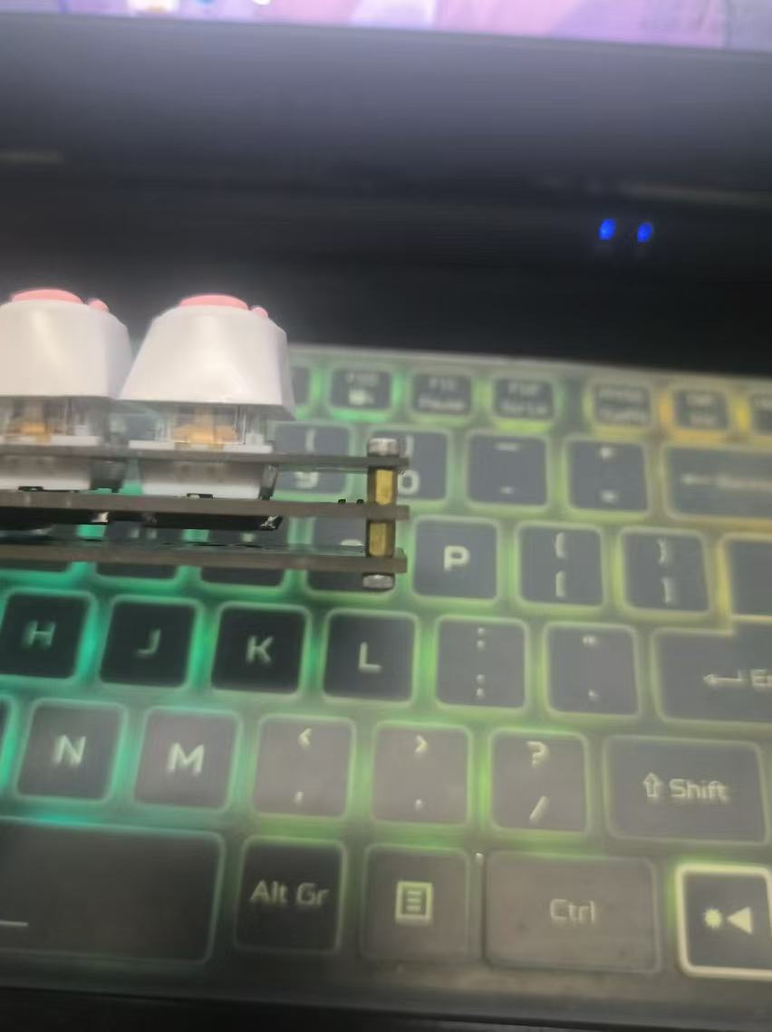
 From top to bottom, there are screws, double-through copper pillars, and single-through copper pillar screws. The top plate (positioning plate) is 1 mm thick, and the other plates are 1.6 mm thick. This design securely holds the mechanical key switch in place, preventing it from moving forward, backward, left, or right, while still allowing for easy insertion and removal. This fixation is already very stable. If you want the mechanical key to be firmly secured to the panel, the original design allows for a 1.6 mm thickness, meaning you need to use a 1.6 mm top plate. Additionally, the length of the copper pillars needs to be adjusted to ensure that the distance from the top surface of the central layer to the top surface of the top plate is 5 mm.
 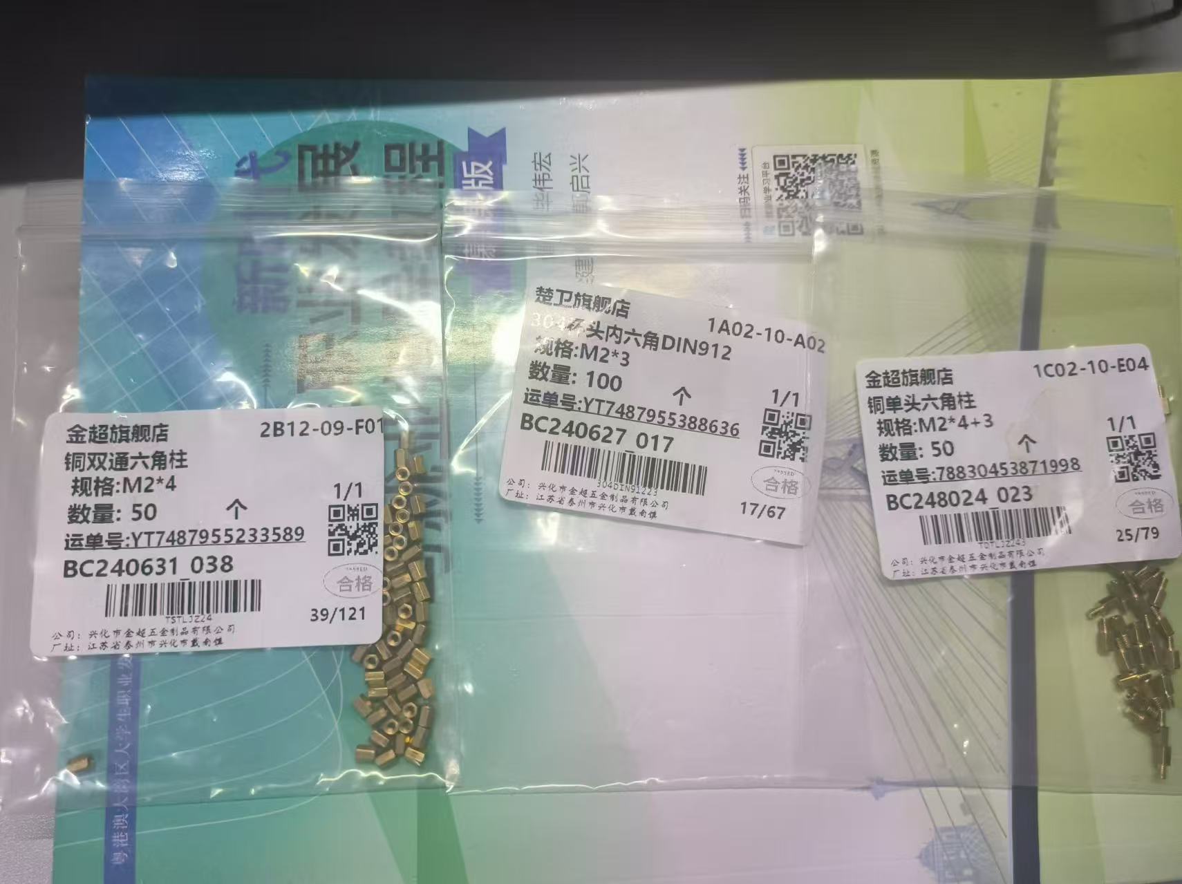 WCHISPTool_Setup.exe - Nanjing Qinheng Microelectronics Co., Ltd.
  An onboard AT24C02 chip ensures data retention even after power loss.
 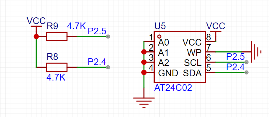 Buttons control the MOSFETs to manage power supply, enabling a hard reset and facilitating program downloading.

All reference designs on this site are sourced from major semiconductor manufacturers or collected online for learning and research. The copyright belongs to the semiconductor manufacturer or the original author. If you believe that the reference design of this site infringes upon your relevant rights and interests, please send us a rights notice. As a neutral platform service provider, we will take measures to delete the relevant content in accordance with relevant laws after receiving the relevant notice from the rights holder. Please send relevant notifications to email: bbs_service@eeworld.com.cn.
It is your responsibility to test the circuit yourself and determine its suitability for you. EEWorld will not be liable for direct, indirect, special, incidental, consequential or punitive damages arising from any cause or anything connected to any reference design used.
Supported by EEWorld Datasheet
EEWorld
subscription
account

EEWorld
service
account

Automotive
development
community

Robot
development
community

About Us Customer Service Contact Information Datasheet Sitemap LatestNews


Room 1530, 15th Floor, Building B,
No.18 Zhongguancun Street,
Haidian District,
Beijing, Postal Code: 100190
China
Telephone: 008610 8235 0740
 京公网安备 11010802033920号

 BUS-61571-200Y


