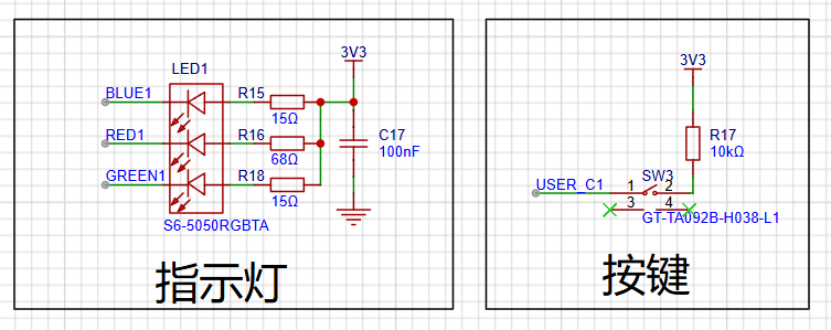
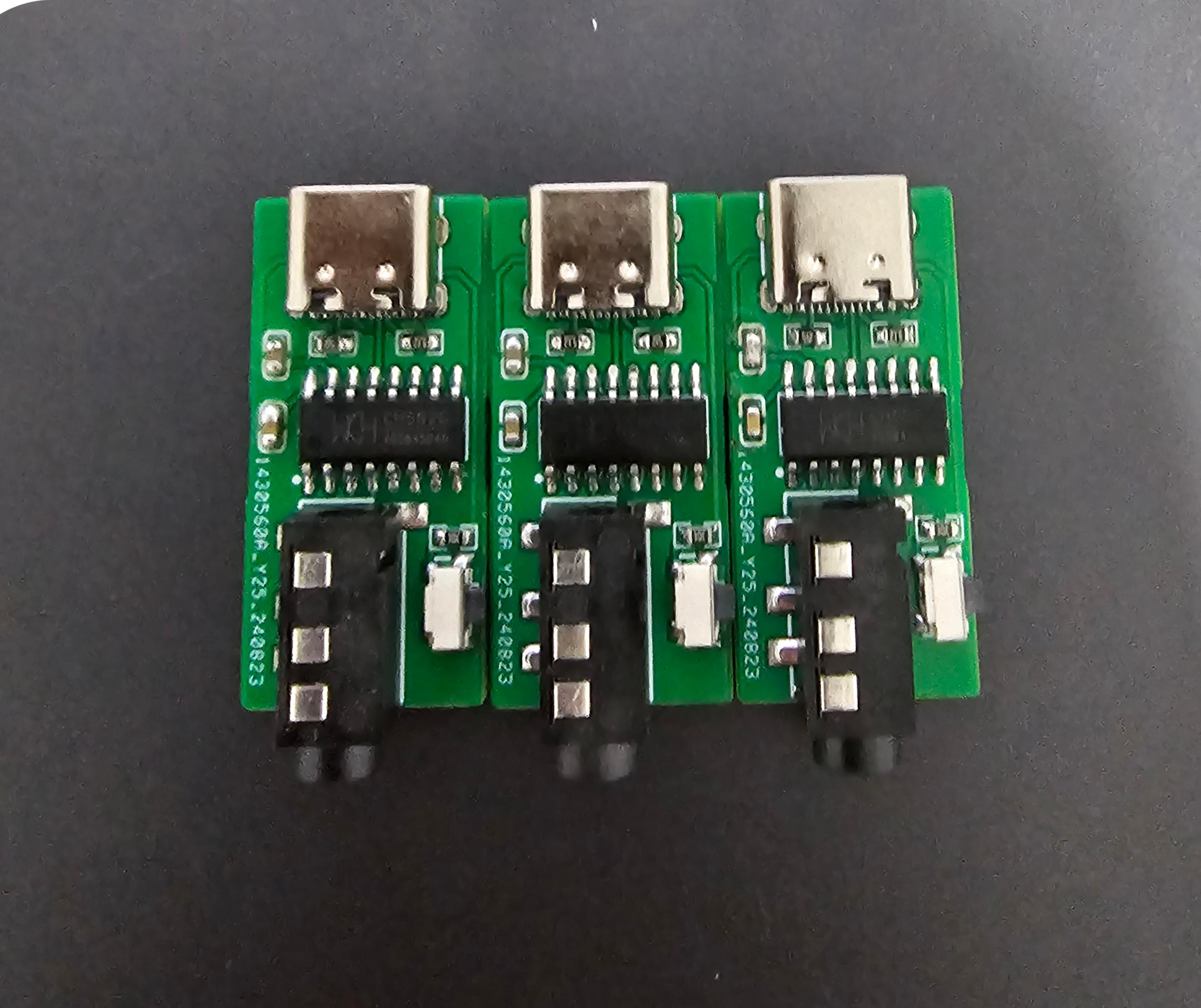
Introduction: This adapter is used to convert Morse code keys to computer software. The key end uses a 3.5mm headphone jack, and the computer end uses a Type-C interface. The main controller is a CH552G. This project references several open-source projects on LCSC that created 3-key keypads; thank you to them.
Usage:
Burning:
1. After PCB soldering, download the Qinheng programmer.
2. Turn on the programmer, press and hold the shorting button on the connector, then insert the data cable to connect to the computer and release the button.
3. Download the attached firmware, select the firmware according to the steps in the image below, and burn it.
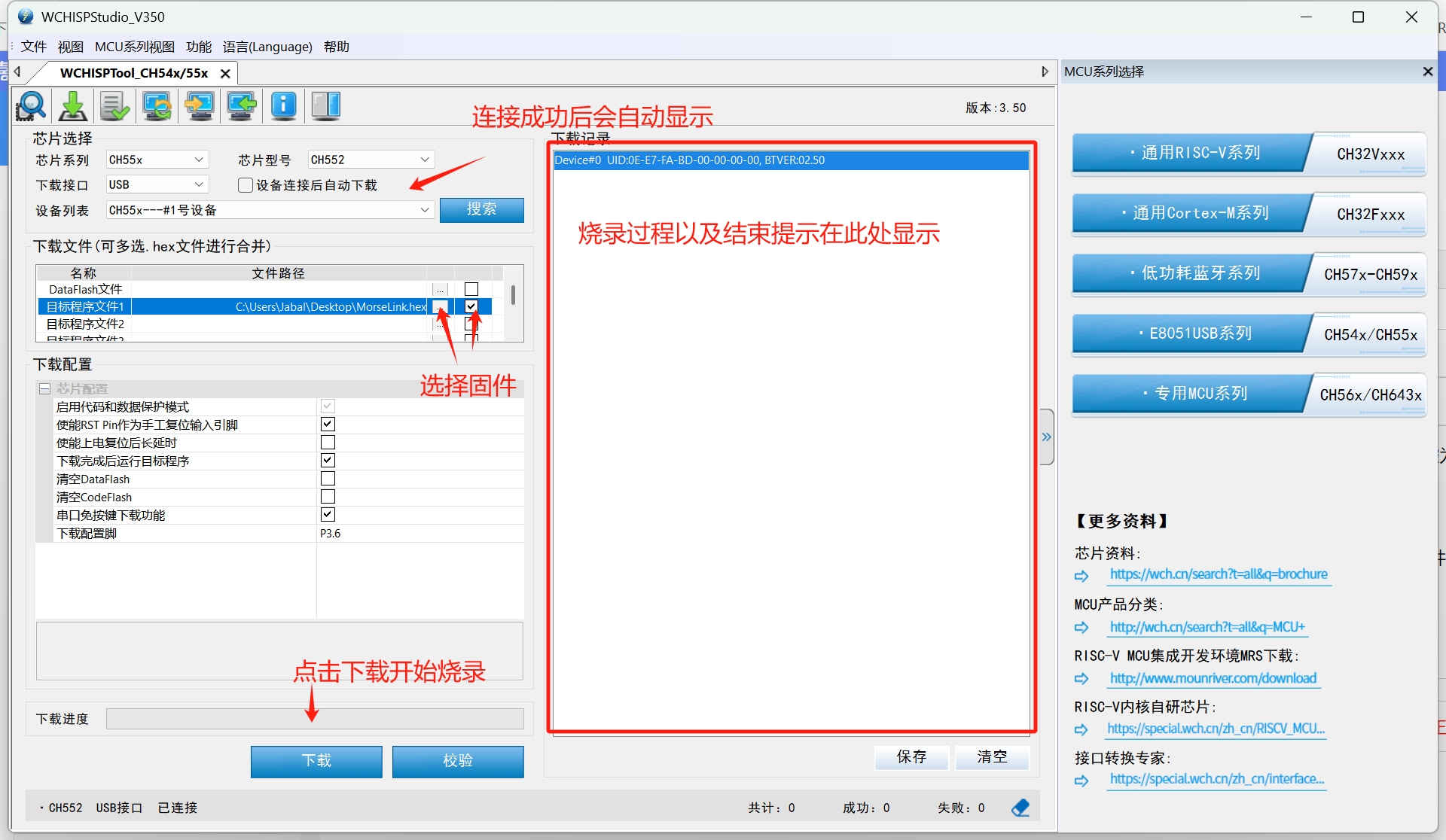
Official firmware download address: [link to firmware download].
Key Remapping:
1. After burning the firmware, use the MorseLink software shown in the image below to remap the keys. MorseLink download address: [link to MorseLink download].
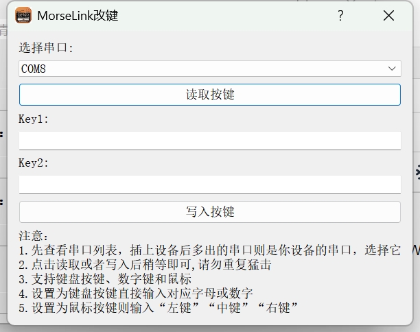
MorseLink.hex
PDF_MorseLink --- CW Key Adapter.zip
Altium_MorseLink --- CW key adapter.zip
PADS_MorseLink --- CW key adapter.zip
BOM_MorseLink --- CW Key Adapter.xlsx
92529
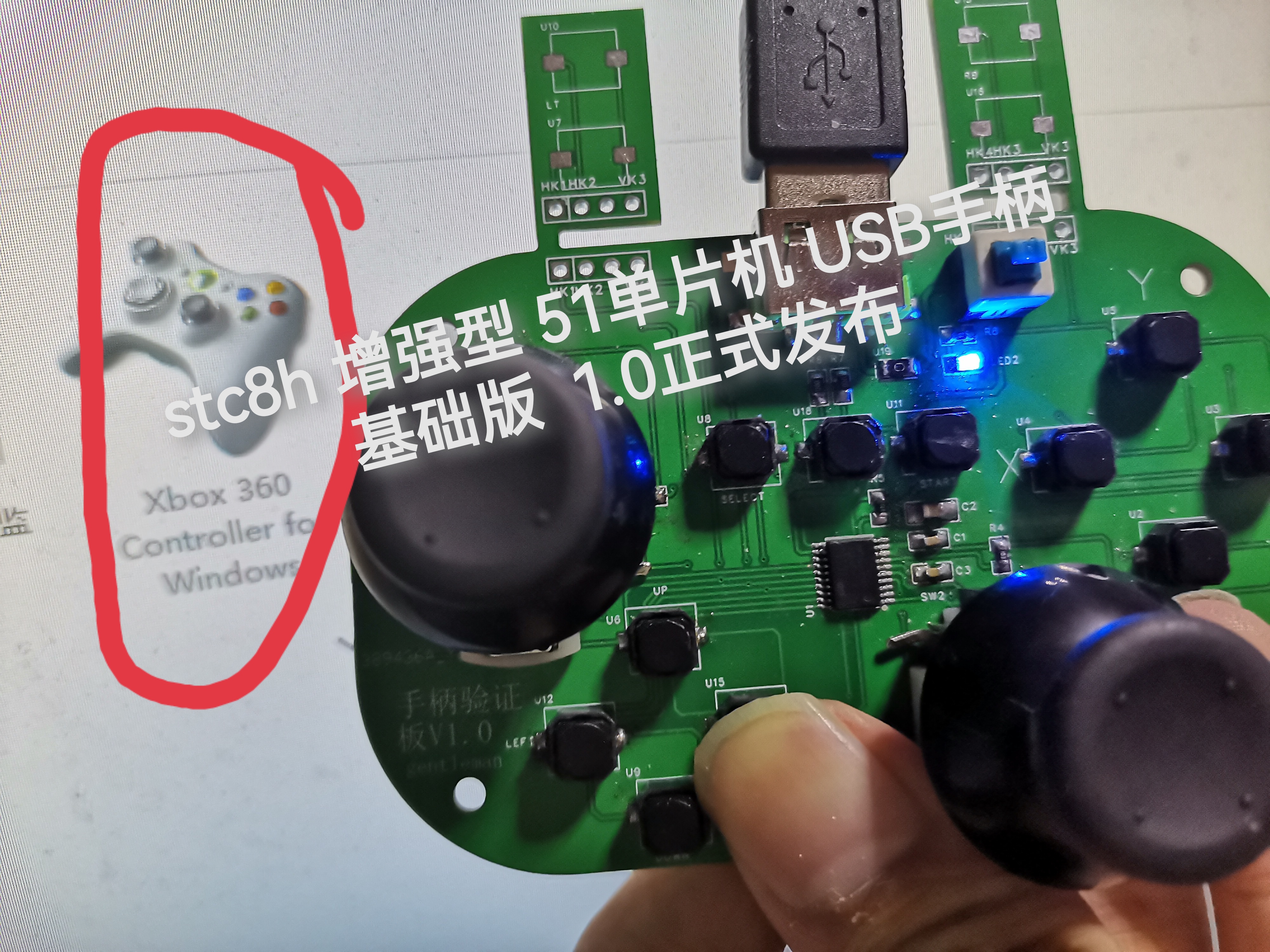
[Global First Release][Original Code] stc8h 51 USB Controller Basic Version
The STC8H enhanced 51 microcontroller USB gamepad uses the 360 gamepad protocol and is driverless for Windows 10 and above.
It's compatible with most gamepads that support this protocol.
The STC8H8K64U 20-pin chip costs only 40 cents.
August 31, 2024: Updated firmware for Gamepad G1S3
to fix button interlocking bug - Macro buttons are temporarily unsupported.
Demo video: https://www.bilibili.com/video/BV1UindeEEme/?share_source=copy_web&vd_source=54fc41cdf2edae385881b75229fda25c
---- Gamepad E2S1 (Elite Board) open source announcement will be released soon.
September 23, 2023: Updated host computer configuration program pre-v2.0 . Updated
firmware for the gamepad G1V2 corresponding to the gamepad.


Bilibili demo link: https://www.bilibili.com/video/BV1qF411S7RQ/
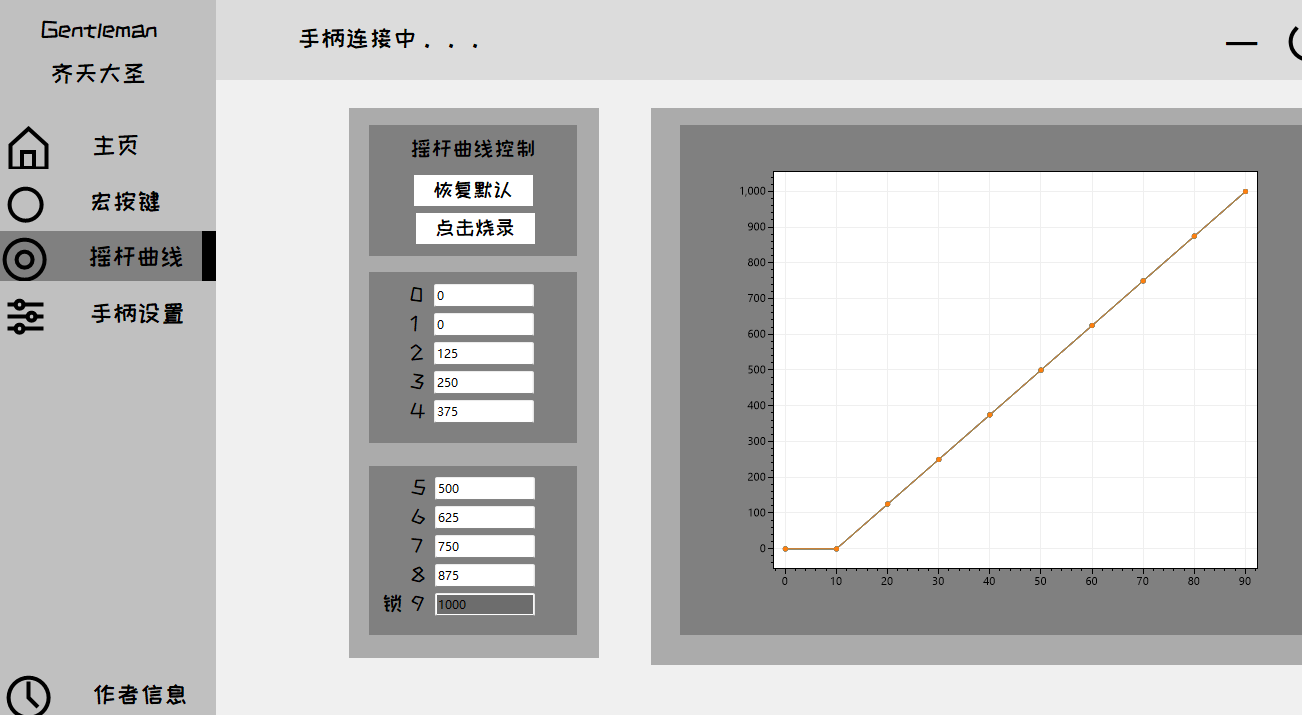
Macro buttons: The gamepad side corresponding to the macro buttons of the 51DIY gamepad host computer has also been developed. Next step: joystick curves_bilibili_bilibili
Long press the watermelon button to enter configuration mode. Currently, the macro button function does not support delay. This is equivalent to a bug in the joystick value of the
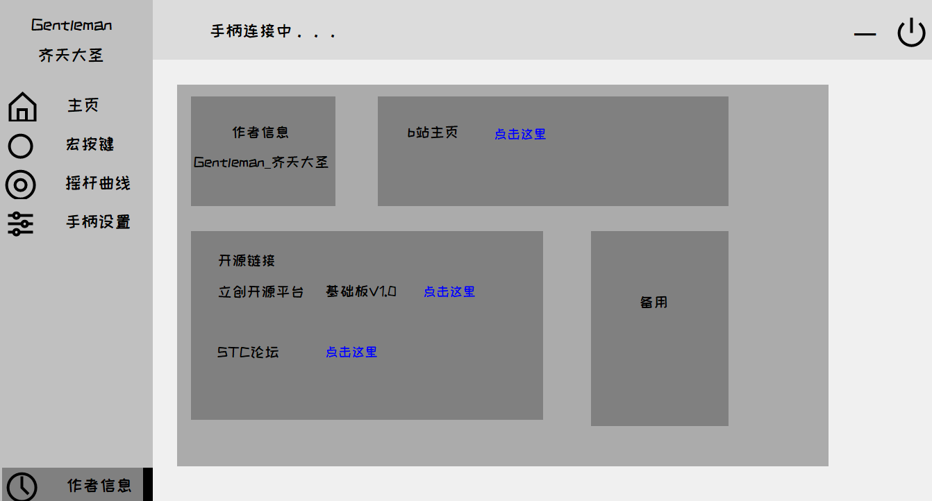
multi-button mapping curve. This will be fixed after the elite version is completed. Remember to set EEPROM to 10k. --------------------------------------------------------------------------------------------------------- Currently, I'm probably the only one using the 51 chip to make a USB gamepad. It's a single 51 chip, without the aid of expansion chips, a global first release, and original code. Disclaimer: The use of the Microsoft 360 gamepad's PID and VID is for educational and exchange purposes only and not for commercial use. This code uses a portion of the STC official test suite example - a USB mouse example based on the HID protocol, version V1.0. Released in September 2023 by Gentleman_齐天大圣. Open source license: GPL 3.0. —————————————————————————————————— Bilibili test video link: https://www.bilibili.com/video/BV14p4y1A7CR/?spm_id_from=333.999.0.0&vd_source=4d02c780af82481d40a80ca841a25329 Game testing [Global First Release: Original Open Source STC8H Enhanced 51 Microcontroller DIY Gamepad Basic Version V1.0 Officially Open Source] The development progress/process of the subsequent advanced version (adding custom back buttons, etc.) will also be shared on Bilibili. Once the advanced version is completed, it will be open-sourced on the LCSC open-source platform and the STC official forum. The basic version uses an STC8H8K64U SSOP20 packaged USB interface. For ease of soldering, a Type-A interface is used; you can replace it with a Type-C interface for replication. The self-locking switch is for programming. If you have an STC USB Link 1D or a dual-purpose programming/debugging tool, you can connect it directly without the switch. To program, press and hold the watermelon button (P3.2 to ground) and power on. --This shouldn't need much explanation. IRC frequency selected 24M // Burning hex files in HID controller stage 4 uildTarget 1. Several resistors on the joystick section can be left unsoldered on the basic board to achieve 13 buttons and 2 axes. The four "ears" are placed on the back for easy testing; normally, they should be connected via ribbon cables on top. Because the joystick potentiometer I bought has a larger package, the two buttons that press down on the joystick are not soldered. I studied software, so the PCB design is rather rough, only for verifying the program. If you have the ability to replicate it, you can optimize the PCB layout and routing, or even redesign it. The test video above is uploaded to Bilibili.
Gamepad configuration tool pre-2.0.7z
Gamepad host computer pre-v2.0 source code.7z
gamepadG1S3.7z
gamepadG1S3.hex
PDF_[Global First Release][Original Code] stc8h 51 USB Controller Basic Version.zip
Altium_[Global First Release][Original Code] stc8h 51 USB Controller Basic Version.zip
PADS_[Global First Release][Original Code] stc8h 51 USB Controller Basic Version.zip
BOM_[Global First Release][Original Code] stc8h 51 USB Controller Basic Version.xlsx
92530
Design of a voltage and current meter based on LCSC's Diwenxing
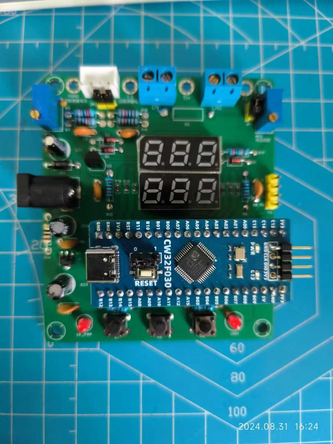
LCSC GeoStar CW32 Digital Voltage and Current Meter Expansion Board
I. Design Background
An ADC (Analog-to-Digital Converter) is an indispensable key component in electronic systems. It converts continuous analog signals into digital signals, enabling digital processing and analysis. ADCs play a crucial role in signal conversion, measurement and data acquisition, control system input, and communication and signal processing. Their widespread application promotes the intelligent and precise control of electronic equipment across various industries, and is one of the key factors driving modern technological progress. Digital voltmeters and ammeters combine ADC technology with circuit measurement principles, accurately converting analog voltage and current signals into digital displays for easy reading and analysis by electronic engineers. This device not only improves the accuracy and efficiency of circuit measurements but also helps engineers better understand circuit behavior, serving as a powerful tool for electronic design and troubleshooting, and playing a vital supporting role in the work of electronic engineers. In product applications, digital voltmeters ensure the accuracy and safety of circuit design, while also providing strong support for product quality control and subsequent maintenance.
II. Function Description
Simultaneously displays current and voltage.
Supports 0~30V voltage measurement with an accuracy of 0.1V. Supports
0~3V small voltage measurement with an accuracy of 0.01V.
Supports 0~3A current measurement
with an accuracy of 0.01A. Features switching and calibration functions
. Onboard circuitry includes both voltage and current measurement circuits for convenient adjustable voltage output for calibration, measurement, and learning.
III. Instructions for Use
1. Daily Use
Voltage Measurement
Wiring: Connect the CH1 terminal to the circuit under test. Connect the yellow wire (+V) to the positive terminal and the black wire (GND) to the negative terminal.
Verification: When verifying with a multimeter, insert the red probe into the pad under the yellow circle on the left and the black probe into the pad under the black circle.
Display: The upward digital tube displays the voltage value. Current
Measurement Wiring
: Connect the CN1 terminal to the circuit under test. Connect the yellow wire (I+) to the positive terminal and the black wire (GND/I-) to the negative terminal.
Verification: When verifying with a multimeter, insert the red probe into the pad under the yellow circle on the right and the black probe into the pad under the black circle. The display
will show:
2. Calibration
voltage calibration:
Jump the JP1 jumper cap to use the onboard analog voltage output circuit.
Press button 1 to change the calibration mode: Press once to display U05. on the upper line of the digital tube to calibrate a 5V voltage. Press twice to display U15. on the upper line to calibrate a 15V voltage.
After selecting the calibration mode, the upper line displays the calibration target, and the lower line displays the current real-time voltage. An external multimeter is required at this time. Connect the multimeter's positive terminal to T_V and the negative terminal to TGND.
Use the RP1 knob to adjust the output voltage until the multimeter reading matches the calibration target. Press button 2 to record and save the calibration results. Calibration is complete. Current
calibration:
Jump the JP2 jumper cap to use the onboard analog current/small voltage output circuit.
Press button 1 to change the calibration mode: Press three times to display A0.5 on the upper line of the digital tube to calibrate a 0.5A current. Press the button four times to display A1.5 when calibrating a 1.5A current.
After selecting the calibration mode, the uplink displays the calibration target, and the downlink displays the current real-time current. An external multimeter is required at this time. Connect the multimeter's positive terminal to TI+ and the negative terminal to TGND.
Use the RP2 knob to adjust the output until the multimeter reading matches the calibration target. Press button 2 to record and save the calibration results. Calibration is complete.
3. Button Operation Summary:
Button 1 is used to switch modes.
Modes 1-4 are for calibration functions. As introduced in the previous section,
mode 5 clears the calibration results in the FLASH memory. Since the calibration results are stored in the FLASH memory and are saved even after power loss, this mode resets the FLASH loading flag in the FLASH memory to no. The theoretical value output result will be calculated at this time.
Button 2 is used to confirm the mode being used .
Button 3 is used to return to monitoring mode or output the current analog current and voltage values via serial port.
When the current mode is not monitoring mode, button 3 returns it to monitoring mode
. When the current mode is monitoring mode, button 3 will output the unprocessed analog values of the measured current and voltage via serial port for easy debugging.
III. Hardware Design
1. Power Supply Circuit
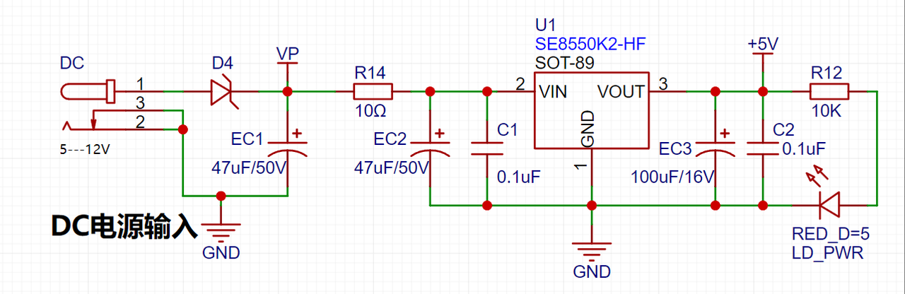
LDO (Low Dropout Linear Regulator) Selection This project uses an LDO as the power supply. Considering that most voltmeter products are used in industrial scenarios with 24V or 36V power supplies, the SE8550K2 with a maximum input voltage of up to 40V was selected as the power supply. The main reason for not using a DC-DC step-down circuit to handle the large voltage drop is to avoid introducing DC-DC ripple interference during the design process; a secondary reason is to reduce project costs.
2. MCU Selection Analysis:
Key Advantages of CW32 in this Project
: Wide operating temperature range: -40~105℃;
Wide operating voltage: 1.65V~5.5V (STM32 only supports 3.3V systems)
; Strong anti-interference: HBM ESD 8KV; All ESD reliability reaches the highest level of international standards (STM32 ESD 2KV);
Project Focus - Better ADC: 12-bit high-speed ADC, achieving ±1.0LSB INL 11.3ENOB; Multiple Vref reference voltages... (STM32 only supports VDD=Vref);
Stable and reliable eFLASH technology.
3. Voltage Sampling Circuit:
The voltage divider resistors in this project are designed as 220K+10K, resulting in a voltage division ratio of 22:1 (ADC_IN11).
The voltage divider resistor selection
is based on the maximum measured voltage; for safety reasons, this project uses 30V (the actual maximum display value can be 99.9V or 100V).
The ADC reference voltage in this project is 1.5V, which can be configured through the program.
To reduce power consumption in the sampling circuit, the low-side resistor (R7) is typically chosen as 10K based on experience.
Range Switching
: In this project, an additional voltage sampling circuit is added; therefore, we can discuss the significance of range switching for improving measurement accuracy. Multimeters often have multiple range settings for more accurate measurements. By adjusting different ranges, the optimal measurement accuracy of the measured point within the corresponding range can be obtained.
This project requires a combination of hardware and software to achieve this function. When we first use the ADC_IN11 channel mentioned above to measure voltages within 30V, if the measured voltage is within 0~3V, then the ADC_IN9 channel is used for measurement. At this point, due to the reduced voltage division ratio, the measurement accuracy is greatly improved. There are many ways to implement gear shifting, and the development board design provides more design possibilities.
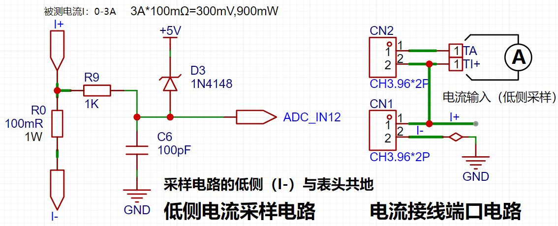
4. Current Sampling Circuit
This project uses a low-side current sampling circuit for current detection. When learning the common ground between the low-side of the sampling circuit and the meter interface on the development board, please do not solder R0!!!

Design Analysis
The sampling current designed in this project is 3A, and the selected sampling resistor (R0) is 100mΩ. The following aspects should be considered when selecting the sampling resistor:
The maximum value of the pre-designed measurement current, in this project, is
the voltage difference caused by the 3A current sensing resistor. It is generally not recommended to exceed 0.5V of
the current sensing resistor's power consumption. A suitable package should be selected based on this parameter. Considering the power consumption (temperature) issue under high current, a 1W packaged metal wire-wound resistor was chosen for
this project. The voltage amplification factor of the current sensing resistor is 1 since no operational amplifier is used in this project.
The current sensing resistance value can then be calculated using the above parameters.
Since no amplifier circuit is used in this project, a larger sampling resistor is needed to obtain a higher measured voltage for measurement
. Considering that a larger resistor will result in a larger voltage difference and higher power consumption, a larger resistor cannot be chosen indiscriminately.
A 1W packaged resistor was selected for this project, corresponding to a temperature rise power of 1W.
Based on the above data, a 100mΩ current sensing resistor was chosen for this project. According to the formula, 3A * 100mΩ = 300mV, 900mW.
To cope with different operating environments, especially high current scenarios, the R0 resistor can be replaced with constantan wire or a shunt. The appropriate alternative can be selected based on the actual application scenario. For safety and educational purposes, this project will not delve into measurements exceeding 3A, but the underlying principles remain the same.
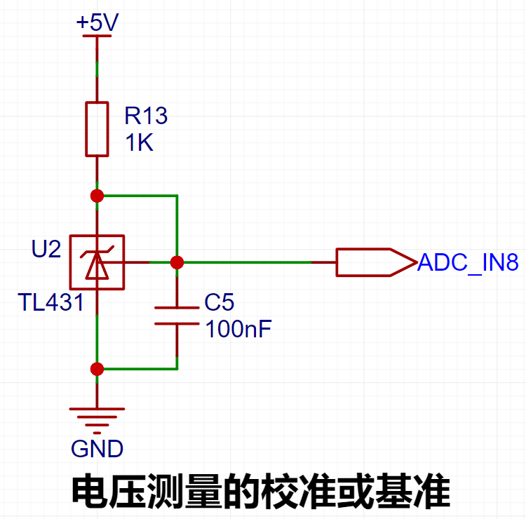
5. TL431 Circuit Design for Voltage Measurement Calibration:
This project adds an extra TL431 circuit to provide a 2.5V reference voltage. This can be used to provide an external voltage reference for calibrating the AD converter. From a product design perspective, due to the inherent ADC performance advantages of the CW32, this circuit is not necessary. This circuit is designed on the development board for learning related application principles.

The TL431 is a relatively "old" device, a classic, and widely used one, still found in many electronic products.
Many beginners may be encountering this device for the first time, so we will briefly explain its principles to facilitate better application of the TL431.
TI defines it as a "Precision Programmable Reference." On the first page of the references, we can focus on several key characteristics.
Precision: Precision indicates that its output voltage is very accurate. I used a ±0.5% accuracy TL431, which measured 2.495V on the board at room temperature. Compared to common Zener diodes, the accuracy is vastly different. In application circuit diagrams, the TL431 is internally represented by a Zener diode symbol.
Adjustable output voltage: The adjustable output voltage is between Vref and 36V. In our project, we use the output Vref voltage. Vref voltage is approximately 2.5V. Therefore, we use 2.5V in the description, which is approximately equal to 1.5V.
Sinking current capability: This refers to how much current the output voltage pin can provide. This is greatly related to the resistance value (R13) in the application circuit. It should not be less than 1mA. If there is no need for sinking current, do not design the current too high, as this will cause unnecessary power consumption.
IV. Product schematic diagram,
soldering completion diagram ,
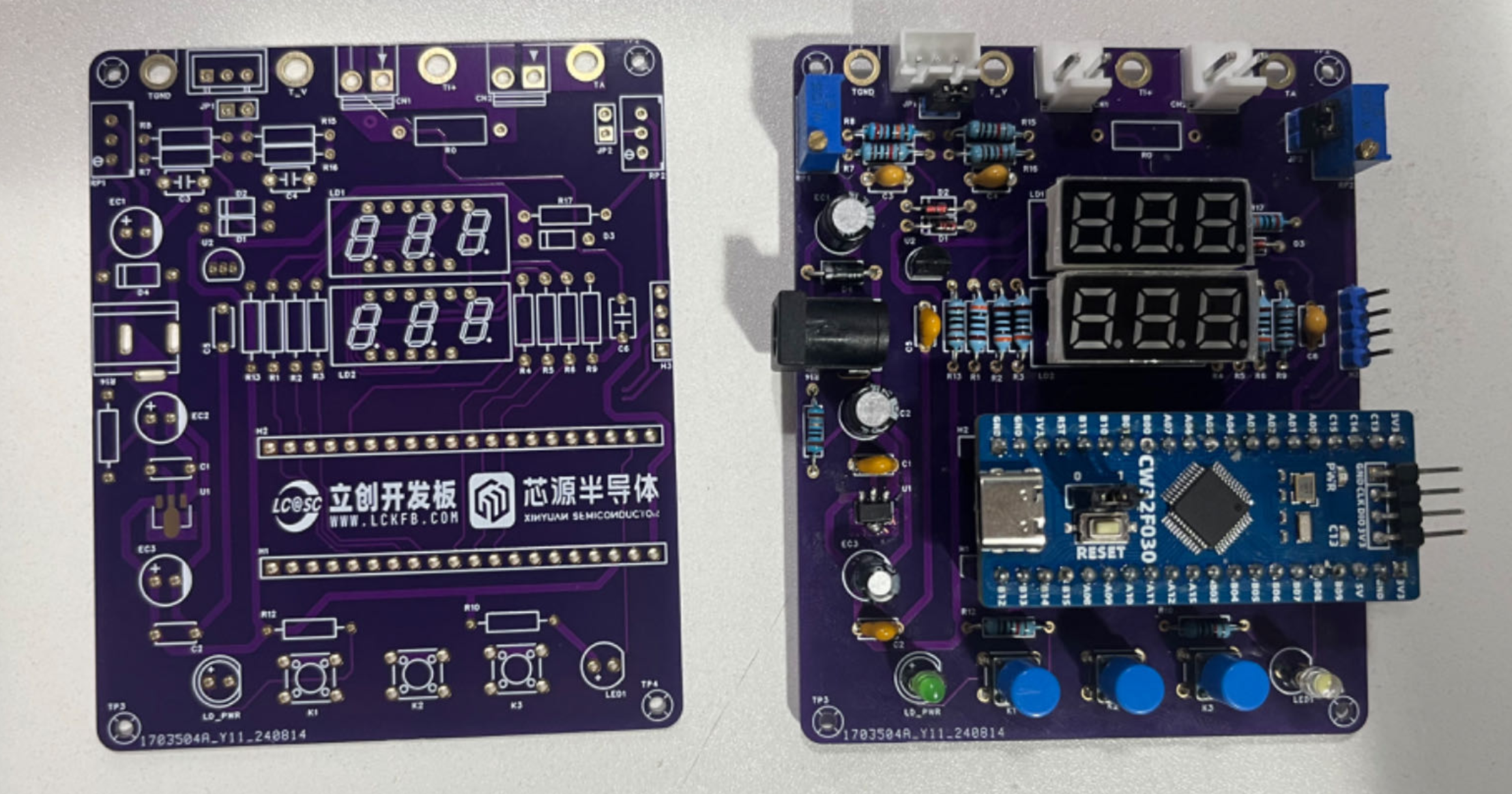
voltage calibration operation diagram.

V. Software design
and debugging, serial port function design
summary: Based on the original serial port function, a serial port redirection function is used, which allows the use of the printf function, with the help of %d and %f, to print integers and decimals, etc.
Functionality Implementation:
First, the C language's `printf` function continuously calls the `fputc` function, so the `fputc` function needs to be rewritten. This function prints a single character, which is the same as the `usart_send_data` function we wrote. The `fputc` function can be written as
`#if !defined(__MICROLIB)
` // If not using the micro-library, the following function needs to be added:
`#if (__ARMCLIB_VERSION`.
Button Functionality Implementation
Summary: The button state is scanned using a timer interrupt function, and the prompt information is displayed using a digital tube function.
Key Code:
'''void BTIM1_IRQHandler(void){ static uint32_t keytime=0,keytime2=0,keytime3=0,ledcount=0; /* USER CODE BEGIN */ if (BTIM_GetITStatus(CW_BTIM1, BTIM_IT_OV)) { BTIM_ClearITPendingBit(CW_BTIM1, BTIM_IT_OV); Get_ADC_Value();if(Mode==0){ledcount++; //LED flash if(ledcount>=1000){PC13_TOG();ledcount=0;}}else if (Mode == 5) { GPIO_WritePin(CW_GPIOC, GPIO_PIN_13, GPIO_Pin_SET); } else { GPIO_WritePin(CW_GPIOC, GPIO_PIN_13, GPIO_Pin_RESET); } timecount++; Display_Refresh(); // Digital tube scanning display if (GPIO_ReadPin(CW_GPIOB, GPIO_PIN_12) == GPIO_Pin_RESET) { keytime++; if (keytime >= 100 ) { keytime = 0; // Switch mode Mode++; if (Mode >= 6) Mode = 0; BrushFlag = 1; // Update digital tube } } else keytime = 0; if (GPIO_ReadPin(CW_GPIOB, GPIO_PIN_13) == GPIO_Pin_RESET && Mode != 0) { keytime2++; if (keytime2 >= 100 ){ keytime2=0; //switch mode if(Mode==1){X05=Mean_Value_Filter(Volt_Buffer,ADC_SAMPLE_SIZE);save_calibration();ComputeK();Volt_Cal();BrushFlag=1;Mode=0;} if(Mode==2){X15=Mean_Value_Filter(Volt_Buffer,ADC_SAMPLE_SIZE);save_calibration();ComputeK();Volt_Cal();BrushFlag=1;Mode=0;}i f(Mode==3){IX05=Mean_Value_Filter(Curr_Buffer,ADC_SAMPLE_SIZE);save_calibration();ComputeK();Volt_Cal();BrushFlag=1;Mode=0;} if(Mode==4){IX15=Mean_Value_Filter(Curr_Buffer,ADC_SAMPLE_SIZE);save_calibration();ComputeK();Volt_Cal();BrushFlag=1;Mode=0;} if (Mode == 5) { clean_calibration(); read_vol_cur_calibration(); BrushFlag = 1; Mode = 0; usart_send_String("Restored"); } } } else keytime2 = 0; if (GPIO_ReadPin(CW_GPIOB, GPIO_PIN_14) == GPIO_Pin_RESET) { keytime3++; if (keytime3 >= 100 ) { if (Mode == 0) { // usart_send_String("Current voltage analog value: %1", V_Buffer); printf("Current voltage analog value: %hu... Current current analog value: %hu", V_Buffer, I_Buffer); } else { keytime3 = 0; // Switch mode Mode = 0; BrushFlag = 1; // Update digital tube } } } else keytime3 = 0; Calibration
Principle
: Calibration compensates for instrument system errors by measuring the deviation of a standard, thereby improving the accuracy and precision of the instrument or system. To improve the measurement accuracy and precision of voltage and current meters, calibration is necessary. A
common calibration principle is as follows:
Assuming a sampling system, the AD section can obtain digital quantities, corresponding to the physical quantity voltage (or current);

the slope k in the above diagram is:
k = (Ymax - Ymin) / (Xmax - Xmin)
(because the first point is the "zero point", Ymin = 0 above).
Therefore, the physical quantity corresponding to the AD value at any point in the above diagram is:
y = k × (Xad - Xmin) + 0.
The above algorithm only calibrates between the "zero point" and the "maximum point". Using intermediate AD sampling values will introduce significant errors in the corresponding physical quantities. The solution is to insert more calibration points.
As shown in the diagram below, four calibration points (x1, y1), (x2, y2), (x3, y3), and (x4, y4) are inserted.

This results in a line segment (equivalent to piecewise processing) instead of a straight line. To calculate the voltage value corresponding to a point Xad between x1 and x2:
y = k × (Xad – X1) + y1.
It can be seen that the more calibration points inserted, the higher the accuracy of the physical value.
When measuring voltage and current with a voltmeter and ammeter, a voltage and current calibration board or a multimeter can be used to calibrate the collected voltage and current. The more calibration points, the more accurate the measurement
.
Program source code.rar
PDF_Design of a Voltage and Current Meter Based on LCSC Geosystems.zip
Altium-based voltage and current meter design using LCSC's Diwenxing.zip
PADS_Design of Voltage and Current Meters Based on LCSC Diwenxing.zip
BOM_Design of Voltage and Current Meters Based on LCSC Diwenxing.xlsx
92532
SkyStar Smart Car Learning Board
The code is entirely based on SkyStar's intelligent car, including line following, obstacle avoidance, Bluetooth remote control, SG90 servo motors, and other multi-functional peripherals. You can also learn about Liangshan School's intelligent car through the LCSC training camp.
Project Introduction
This project is a smart car based on the LCSC Skystar GD32 microcontroller. The code is entirely based on the official Skystar example code and includes line following, obstacle avoidance, and Bluetooth remote control functions. You can also learn about the Liangshan School of Smart Cars through the LCSC training camp.
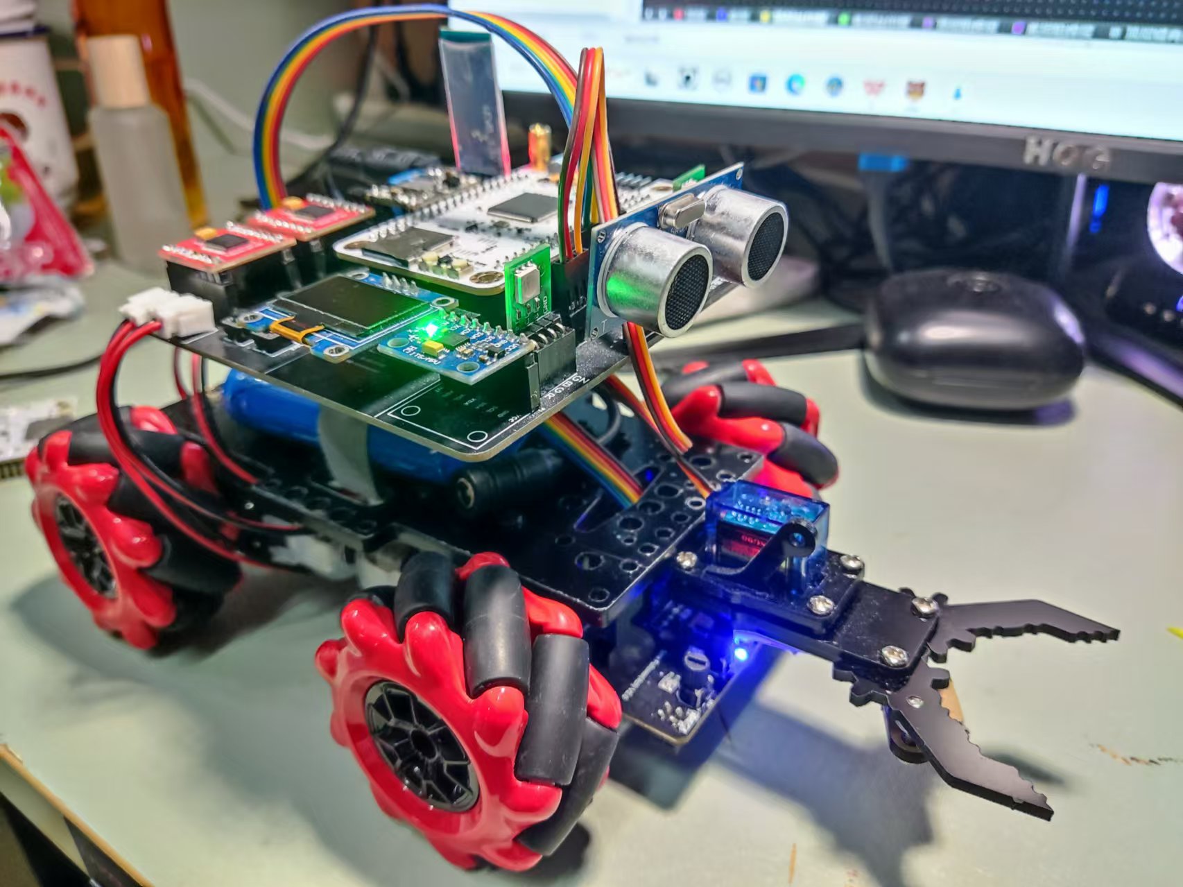
The entire car adopts a modular design, which facilitates component reuse and simplifies soldering for beginners, making it very suitable for beginners learning about smart cars for the first time.
Principle Analysis
The overall design scheme of the Skystar smart car system is shown in the figure below. The power supply circuit uses a 12V lithium battery, which is stepped down to 5V to power the microcontroller system via a step-down chip. The LCSC Skystar core board is connected to the LED lights, button circuit, obstacle avoidance circuit, line following circuit, Bluetooth remote control circuit (wireless remote control function), buzzer, and motor drive circuit on the smart car expansion board.
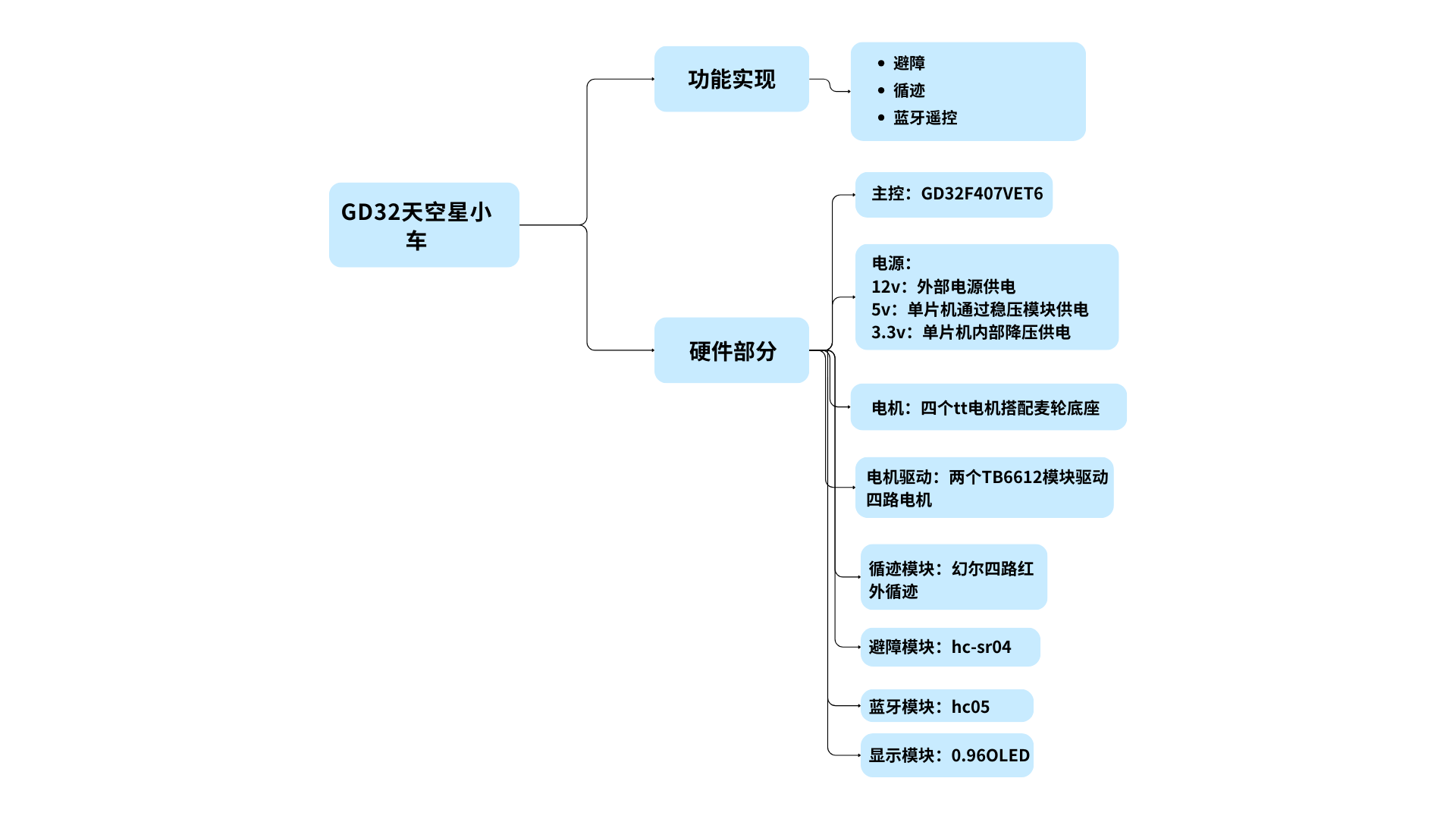
Implemented Functions
1. Obstacle Avoidance Mode: When the car encounters an obstacle while moving forward, it can rotate in place to avoid the obstacle. (Template1)
2. Line Following Mode: The car can follow the black line on the ground. (Template2)
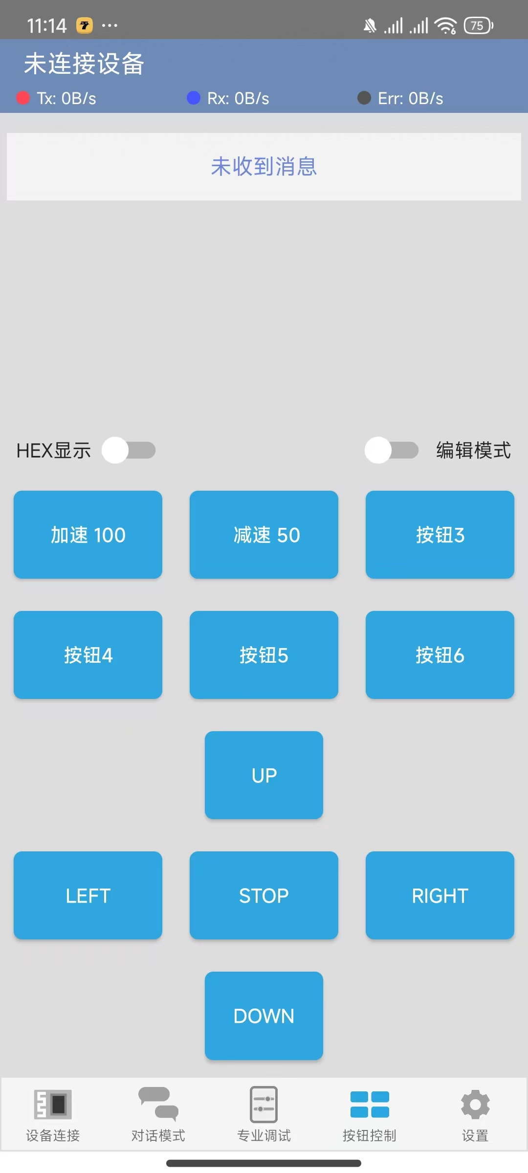
3. Bluetooth Remote Control: Controls the car's forward, backward, left, and right movement, as well as its left and right rotation and stopping. (Template3)
4. Integrated Code Button Switching (Integrated)
Bluetooth button assignments need to be modified manually!!!
Pin Assignments (module list also included)
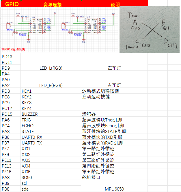
Intelligent Car Code Function Description Based on LCSC Skystar GD32
1. LED Lights:
The car has two RGB lights at the front, one on each side.
2. Buttons:
The car's expansion board has four independent buttons, KEY1, KEY2, KEY3, and KEY4, which can be used for starting and switching movement modes. Specific implementations are shown in the code examples.
3. Buzzer:
The car is equipped with a buzzer, which can be used to sound an alarm when encountering obstacles .
4. Ultrasonic Module:
There is an HCSR04 ultrasonic module at the front of the car, which can be used for ultrasonic obstacle avoidance.
5. Motors:
The car has four motors, driven by the TB6612 chip. It can move forward, backward, turn left, turn right, and stop (brake/off). Combined with the timer PWM function, the car's speed can be changed.
6. Tracking:
The car is equipped with 4-channel infrared tracking, which can be used to follow black lines. Five channels are reserved for future modification to a 5-channel tracking capability; this is pre-defined in the code and can be modified as needed.
7. Obstacle Avoidance:
The car can use an ultrasonic module to perform obstacle avoidance.
8. Bluetooth Module:
The car provides a Bluetooth module interface, allowing for wireless remote control via a mobile Bluetooth app.
9. Servo Motor
: The car has a reserved servo motor interface circuit for adding external mechanical clamps.
10. 1.8-inch TFT and 0.96 OLED Display:
The car has reserved interface circuits for 1.8-inch TFT and 0.96 OLED displays. (Note the positive and negative pins of the purchased OLED)
Current Issues: !!
1. The button debouncing function is incorrect; this only affects sensitivity and can be modified manually.
2. The PCB positioning hole size is incorrect and may not fully fit the car base; the positioning holes need to be modified according to the car chassis. (Please add at least one or two M3 screw positioning holes before placing an order, otherwise assembly will not be possible!!!)
3. The buzzer uses a low-level trigger module, and there seems to be a problem with the code, causing it to keep beeping.
Physical Image
Software Description (Configuration Section)
1. LED (Single Section Only)
Configuration Left RGB Blue LED
void led_gpio_config(void)
{
/* Enable clock */
rcu_periph_clock_enable(LED_BL);
/* Configure output mode as floating mode */
gpio_mode_set(PORT_LED_BL,GPIO_MODE_OUTPUT,GPIO_PUPD_NONE,LED_BL_PIN);
/* Configure as push-pull output 50MHZ */
gpio_output_options_set(PORT_LED_BL,GPIO_OTYPE_PP,GPIO_OSPEED_50MHZ,LED_BL_PIN);
}
Example: Turn off all left/right LEDs
void led_l_off(void)
{
gpio_bit_write(PORT_LED_RL,LED_RL_PIN,RESET);
gpio_bit_write(PORT_LED_GL,LED_GL_PIN,RESET);
`gpio_bit_write(PORT_LED_BL,LED_BL_PIN,RESET);
}
void led_r_off(void)
{
gpio_bit_write(PORT_LED_RR,LED_RR_PIN,RESET);
gpio_bit_write(PORT_LED_GR,LED_GR_PIN,RESET);
gpio_bit_write(PORT_LED_BR,LED_BR_PIN,RESET);
}`
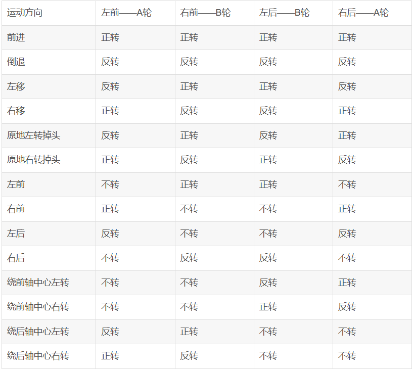
2. Motor Drive and Attitude Control
TB6612 Configuration: Please refer to the example code provided by LCSC for this part and verify that the configuration is complete.
Below are two control methods; you can modify them according to your personal preference.
/******************************************************************
* Function Name: AO_Control
* Function Description: A-port motor control
* Function Parameters: dir: Rotation direction 1 (forward), 0 (reverse) speed: Rotation speed, range (0 ~ per-1)
******************************************************************/
void AO_Control(uint8_t dir, uint32_t speed)
{
if( dir == 1 )
{
AIN1_OUT(0);
AIN2_OUT(1);
}
else
{
AIN1_OUT(1);
AIN2_OUT(0);
}
timer_channel_output_pulse_value_config(BSP_PWMA1_TIMER,BSP_PWMA1_CHANNEL, speed );
}
void SetPWMA(int speed)
{
if(speed>=0)//pwm>=0 (AIN1, AIN2)=(0, 1) forward clockwise
{
AIN1_OUT(1);
AIN2_OUT(0);
timer_channel_output_pulse_value_config(BSP_PWMA1_TIMER,BSP_PWMA1_CHANNEL, speed );
}
if(speed<0)//pwm<0 (AIN1, AIN2)=(1, 0) reverse counterclockwise
{
AIN1_OUT(0);
AIN2_OUT(1);
timer_channel_output_pulse_value_config(BSP_PWMA1_TIMER,BSP_PWMA1_CHANNEL, -speed );
}
if(speed==0)
{
AIN1_OUT(1);
AIN2_OUT(1);
timer_channel_output_pulse_value_config(BSP_PWMA1_TIMER,BSP_PWMA1_CHANNEL, -speed );
}
}
Control Section
/**********************************************************************
* Function Name: motor
* Function Description: Overall Control Section
****************************************************************/
void car_stop(uint32_t speed) //Car stops
{ SetPWMA(0);
SetPWMB(0);
SetPWMC(0);
SetPWMD(0);}
void car_front(uint32_t speed) //Car moves forward
{ SetPWMA(speed);
SetPWMB(speed);
SetPWMC(speed);
SetPWMD(speed);}
void car_back(uint32_t speed) //Car moves backward
{ SetPWMA(-speed);
SetPWMB(-speed);
SetPWMC(-speed);
SetPWMD(-speed);}
void car_left(uint32_t speed) //Car moves left
{ SetPWMA(-speed);
SetPWMB(speed);
SetPWMC(speed);
SetPWMD(-speed);}
void car_right(uint32_t speed) //Car moves right
{ SetPWMA(speed);
SetPWMB(-speed);
SetPWMC(-speed);
SetPWMD(speed);}
void car_on_left(uint32_t speed) //Car turns left in place
{ SetPWMA(-speed);
SetPWMB(speed);
SetPWMC(-speed);
SetPWMD(speed);}
void car_on_right(uint32_t speed) //Car turns right in place
{ SetPWMA(speed);
SetPWMB(-speed);
SetPWMC(speed);}
SetPWMD(-speed);}
void car_front_left(uint32_t speed) //Car moves forward to the left
{ SetPWMA(0);
SetPWMB(speed);
SetPWMC(speed);
SetPWMD(0);}
void car_back_left(uint32_t speed) //Car backs to the left
{ SetPWMA(-speed);
SetPWMB(0);
SetPWMC(0);
SetPWMD(-speed);}
void car_back_right(uint32_t speed) //Car backs to the right
{ SetPWMA(0);
SetPWMB(-speed);
SetPWMC(-speed);
SetPWMD(0);}
void car_front_right(uint32_t speed) //Car moves forward to the right
{ SetPWMA(speed);
SetPWMB(0);
SetPWMC(0);
SetPWMD(speed);}
void car_center_front_left(uint32_t speed) //Car turns left around the center of the front axle
{ SetPWMA(0);
SetPWMB(0);
SetPWMC(-speed);
SetPWMD(speed);}
void car_center_front_right(uint32_t `speed)` // The car turns right around the center of the front axle
{ SetPWMA(0);
SetPWMB(0);
SetPWMC(speed);
SetPWMD(-speed);} `
void car_center_back_left(uint32_t speed)` // The car turns left around the center of the rear axle
{ SetPWMA(-speed);
SetPWMB(speed);
SetPWMC(0);
SetPWMD(0);} `
void car_center_back_right(uint32_t speed)` // The car turns right around the center of the rear axle
{ SetPWMA(speed);
SetPWMB(-speed);
SetPWMC(0);
SetPWMD(0);}
Two control methods are used, and you can choose whichever you prefer.
3. OLED (The onboard OLED is 0.96; 1.8 is not very useful and is only used for learning)
The code will not be shown here. Please directly learn from LCSC's configuration tutorial.
4. The HC-SR04
ultrasonic ranging principle is that the ultrasonic transmitter emits ultrasonic waves and starts timing at the same time. The ultrasonic waves propagate in the air. When they encounter an obstacle, they will send a signal back to the ultrasonic receiver. The ultrasonic receiver stops timing immediately after receiving the signal. At this time, there will be a time t. The speed of ultrasonic waves in the air is 340m/s. The distance to be measured can be calculated by the formula s=340 xt / 200. (Refer to official example code)
HC-SR04 Ultrasonic Ranging Module Working Principle:
Working voltage: DC 5V;
Ranging is triggered by I/O port. The microcontroller sends a high-level signal of at least 10us to the Trig pin of the ultrasonic module to trigger its operation.
The module's transmitting probe automatically sends eight 40KHz square wave signals and automatically detects whether a signal is returned.
If a signal is returned, a high-level signal is output through the Echo pin connected to the microcontroller's I/O port. The duration of the high-level signal is the time from ultrasonic emission to return.
Based on the speed of sound in air being 340 meters per second, the measured distance can be calculated.
5. Five-channel Infrared
Tracking: The tracking principle involves connecting pin 1 of the voltage comparator to a pin on the microcontroller. The I/O is configured as input mode. When pin 1 of the voltage comparator outputs a high level, it indicates that the infrared light is absorbed, a black line is detected, the LED indicator lights up, and the microcontroller I/O reads the high level.
The principle of infrared tracking: It utilizes the reflection of infrared light at different colors to identify and
detect black lines. An infrared emitter emits light to the ground; when the infrared light encounters a white ground surface, it is reflected. The infrared receiver receives the reflected light, and after passing through a voltage comparator, it outputs a low level.
The principle of detecting black lines is that an infrared emitter emits light to the ground; when the infrared light encounters a black ground surface, it is absorbed. The infrared receiver does not receive the reflected light, and after passing through a voltage comparator, it outputs a high level.
#include "bsp_IRtracking.h"
#include "board.h"
#include "stdio.h"
FlagStatus XJ01 = RESET;
FlagStatus XJ02
= RESET; FlagStatus XJ03 =
RESET; FlagStatus XJ04 = RESET;
//FlagStatus XJ05 = RESET;
/****
Function Name: track_gpio_config
Function: Tracking GPIO pin configuration
Parameters: None
Return Value: None
*****/
void track_gpio_config(void)
{
/ Enable clock /
rcu_periph_clock_enable(XJ01_RCU);
/ Configure as input mode pull-up mode /
gpio_mode_set(PORT_XJ01,GPIO_MODE_INPUT,GPIO_PUPD_PULLUP,XJ01_PIN);
/* Enable clock */
rcu_periph_clock_enable(XJ02_RCU);
/* Configure as input mode pull-up mode */
gpio_mode_set(PORT_XJ02,GPIO_MODE_INPUT,GPIO_PUPD_PULLUP,XJ02_PIN);
/* Enable clock */
rcu_periph_clock_enable(XJ03_RCU);
/* Configure as input mode pull-up mode */
gpio_mode_set(PORT_XJ03,GPIO_MODE_INPUT,GPIO_PUPD_PULLUP,XJ03_PIN);
/* /* Enable clock */
rcu_periph_clock_enable(XJ04_RCU);
/* Configure as input mode pull-up mode */
gpio_mode_set(PORT_XJ04,GPIO_MODE_INPUT,GPIO_PUPD_PULLUP,XJ04_PIN);
// / Enable clock/
// rcu_periph_clock_enable(XJ05_RCU);
// / Configure as input mode pull-up mode/
// gpio_mode_set(PORT_XJ05,GPIO_MODE_INPUT,GPIO_PUPD_PULLUP,XJ05_PIN);
}
/****
Function Name: Black_Line_Detection
Function: Black line detection function
Parameters: None
Return Value: None
*****/
void Black_Line_Detection(void)
{
XJ01 = gpio_input_bit_get(PORT_XJ01,XJ01_PIN);
XJ02 = `gpio_input_bit_get(PORT_XJ02,XJ02_PIN);
XJ03 = gpio_input_bit_get(PORT_XJ03,XJ03_PIN);
XJ04 = gpio_input_bit_get(PORT_XJ04,XJ04_PIN);
// XJ05 = gpio_input_bit_get(PORT_XJ05,XJ05_PIN);
}
# **6. Button Definition**
The circuit design principle of an independent button is to connect one end of the button to the microcontroller's I/O port and the other end to ground. When the button is pressed, a low level is read; when the button is released, a high level is read. Note that the I/O port needs to be configured as a pull-up input.`
include "bsp_key.h"
uint8_t uckey=0;
uint8_t Motion_Mode=0;//Motion mode, default is tracking mode
uint8_t Start_Flag=0; //Car start button flag, default is no start, i.e., the car stops
static uint8_t num_flag = 1;//Cycle from 1 to 3, 1, 2, 3 represent obstacle avoidance, tracking, and Bluetooth remote control states
/****
Function Name: key_gpio_config
Function: Independent button GPIO pin configuration
Parameters: None
Return Value: None
*****/
void key_gpio_config(void)
{
/* Enable clock */
rcu_periph_clock_enable(BSP_KEYM_RCU);
rcu_periph_clock_enable(BSP_KEYS_RCU);
/* Configure as input mode pull-up mode */
gpio_mode_set(BSP_KEYM_PORT,GPIO_MODE_INPUT,GPIO_PUPD_PULLUP,BSP_KEYM_PIN); // The button's default state is high, configured as pull-up
gpio_mode_set(BSP_KEYM_PORT,GPIO_MODE_INPUT,GPIO_PUPD_PULLUP,BSP_KEYM_PIN); // The button's default state is high, configured as pull-up
}
/****
Function Name: BSP_KEYM_EXTI_IRQHandler
Function: Interrupt Handling Function
Parameters: None
Return Value: None
*****/
void BSP_KEYM_EXTI_IRQHANDLER(void)
{
if(exti_interrupt_flag_get(BSP_KEYM_EXTI_LINE) == RESET) // Interrupt flag is 0, button pressed
{
if(gpio_input_bit_get(BSP_KEYM_PORT,BSP_KEYM_PIN) == RESET) // Key pressed
{
/ Function of key pressed /
} else { // Key released
/* Function of key released */
}
exti_interrupt_flag_clear(BSP_KEYM_EXTI_LINE); // Clear the interrupt flag
}
}
/****
Function Name: KEY_Read
Function: Key read function
Parameters: None
Return Value: Corresponding key flag
*****/
uint8_t KEY_Read(void)
{
uint8_t key_val=0;
/ First read the level of the key pin. If it is low, the key is pressed. /
if(gpio_input_bit_get(BSP_KEYM_PORT,BSP_KEYM_PIN) == RESET) // Key pressed
{
delay_ms(100); // Debounce delay
if(gpio_input_bit_get(BSP_KEYM_PORT,BSP_KEYM_PIN) == RESET) // Check if the key is pressed again
key_val=1;
}
/* First read the level of the key pin. If it is low, the key is pressed. */
if(gpio_input_bit_get(BSP_KEYS_PORT,BSP_KEYS_PIN) == RESET) // Key pressed
{
delay_ms(100); // Debounce
if(gpio_input_bit_get(BSP_KEYS_PORT,BSP_KEYS_PIN) == RESET) // Check if the key is pressed again
key_val=2;
}
return key_val;
}
/****
Function Name: KEY_Proc
Function: Key press execution program
Parameters: None
Return Value: None
*****/
void KEY_Proc(void)
{
uint8_t key_val=0;
key_val = KEY_Read();
if(key_val != uckey)
uckey=key_val;
else
key_val = 0;
switch(key_val)
{
case 1://1
Motion_Mode^=1;
break;
case 2://2
Start_Flag^=1;
break;
default:
break;
}
}
uint8_t KEY_get(void)
{
if(KEY_Read()==1)
{
num_flag +=1;
if(num_flag ==4)
{
num_flag = 1;
}
}
return num_flag;
}
Intelligent Car Expansion Board Pin Assignment.xlsx
GD32-sky_CAR.zip
Multifunctional peripherals showcase.mp4
PDF_SkyStar Smart Car Learning Board.zip
Altium_SkyStar Smart Car Learning Board.zip
PADS_SkyStar Smart Car Learning Board.zip
BOM_SkyStar Smart Car Learning Board.xlsx
92534
Voltmeter and Ammeter
CW32 Digital Voltage and Current Meter
I. Design Background
The CW32 digital voltmeter and ammeter combines ADC technology with circuit measurement principles, accurately converting analog voltage and current signals into digital displays for easy reading and analysis by electronic engineers.
II. Hardware Design
1. Power Supply Circuit: This project uses the SE8550K2 as an LDO (Low Dropout Linear Regulator).
2.

MCU Selection:
This project uses the CW32F030C8T6 MCU.
Key Advantages of the CW32 in this Project
: Wide operating temperature range: -40~105℃;
Wide operating voltage range: 1.65V~5.5V (STM32 only supports 3.3V systems);
Strong anti-interference: HBM ESD 8KV; All ESD reliability reaches the highest international standard level (STM32 ESD 2KV)
; Project Focus - Better ADC: 12-bit high-speed ADC, achieving ±1.0LSB INL 11.3ENOB; Multiple Vref reference voltages... (STM32 only supports VDD=Vref);
Stable and reliable eFLASH technology. (Flash0 waiting)
3.
Voltage Sampling Circuit
: A voltage divider circuit is used to achieve high voltage acquisition, capable of acquiring 100V. The voltage divider resistor is designed as 220K+10K, therefore the voltage division ratio is 22:1 (ADC_IN11).

4. Current Sampling Circuit:
A low-side current sampling circuit is used for current detection. The low side of the sampling circuit shares a common ground with the development board's meter interface. The sampling current designed in this project is 3A, and the selected sampling resistor (R0) is 100mΩ.
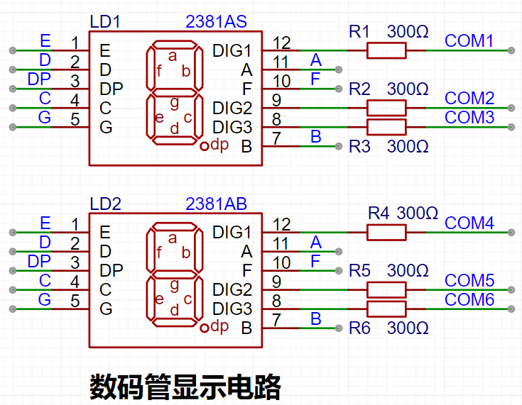
5. Digital Tube Driver
6. Indicator Lights

7.
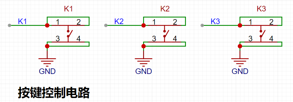
Button Circuit Design
8. TL431 Circuit Design
III. Button Functions
K1 key is used to switch display modes. K2 key sets the parameter value in the corresponding mode and saves it to FLASH. K3 key returns to mode 0.
Mode 0: Displays normal voltage and current values (the upper row of digital tubes displays the voltage value *.V or .*V automatically switches, the lower row displays the current value, _.**A).
Mode 1: Voltage 5V calibration value setting. The upper row of digital tubes displays 5.05. The next row displays the current voltage value as _.V or ._V. In this mode, the multimeter should be set to 5.00V when measuring the measured position. Pressing the K2 key will calibrate the current value to 5V.
Mode 2: 15V voltage calibration setting. The previous row of the digital display shows 5.15. The next row displays the current voltage value as _.V or ._V. In this mode, the multimeter should be set to 15.0V when measuring the measured position. Pressing the K2 key will calibrate the current value to 15V.
Mode 3: 0.5A current calibration setting. The previous row of the digital display shows A.0.5. The next row displays the current current value as _.**A. Pressing the K2 key will calibrate the current value to 0.5A.
Mode 4: 1.5A current calibration setting. The previous row of the digital display shows A.1.5. The next row displays the current current value as *.**A. Pressing the K2 key will set the current value to 1.5A
.
bb969eee0a2959cf09eff4ce0b98334a.mp4
PDF_Voltage and Current Meters.zip
Altium_voltmeter_currentmeter.zip
PADS_Voltage and Current Meter.zip
BOM_Voltage and Current Meter.xlsx
92535
Taishanpai Multi-Screen Expansion Board
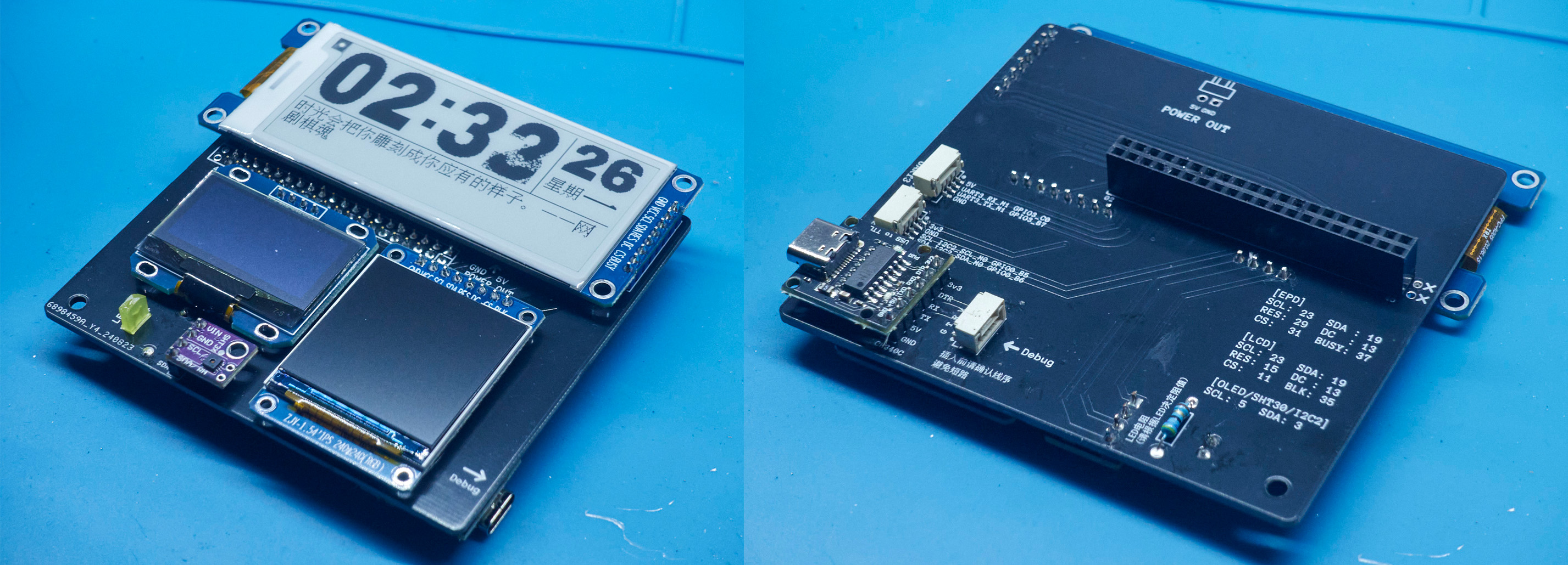
Connect to Taishanpai's 40-pin multi-type screen expansion board, including e-ink screens, OLED screens, and LCD screens, which can be used for development, learning, or building personalized display content.

This 40-pin expansion board with three screens can be used for development and learning, or, when paired with a casing, transforms the Taishanpai into a mini desktop computer, allowing users to customize the screen display content.
Key features include
: a 2.9-inch monochrome e-ink screen module (128*296, driver: SSD1680)
from Zhongjingyuan; a 1.54-inch TFT display module (240*240, driver: ST7789) from Zhongjingyuan;
a 0.96-inch OLED module (128*64, driver: SSD1306)
; a CH340C module for easy serial port debugging;
an LED indicator light; and
an SHT30 temperature and humidity module
casing. The
casing uses 3D printing and a custom panel from JLCPCB, which covers the front and can be replaced with a 3D printed panel.
The Taishanpai is secured to the casing with four 10mm high copper pillars, and the expansion board is then plugged into the 40-pin interface.
On the left side, there's a hole for the button, making it easy to press.
On the right side, there are holes for Debug, serial port, and I2C output (the Type-C port for Debug is small and difficult to connect; the model could be modified to enlarge the hole)
. The lower left corner can be glued with hot glue to the power module included with the Taishanpai; there's an opening at the back for power supply from the rear.
The top has holes for the Taishanpai interface, as well as a circular antenna hole for extending the antenna or inserting an SMA interface antenna.

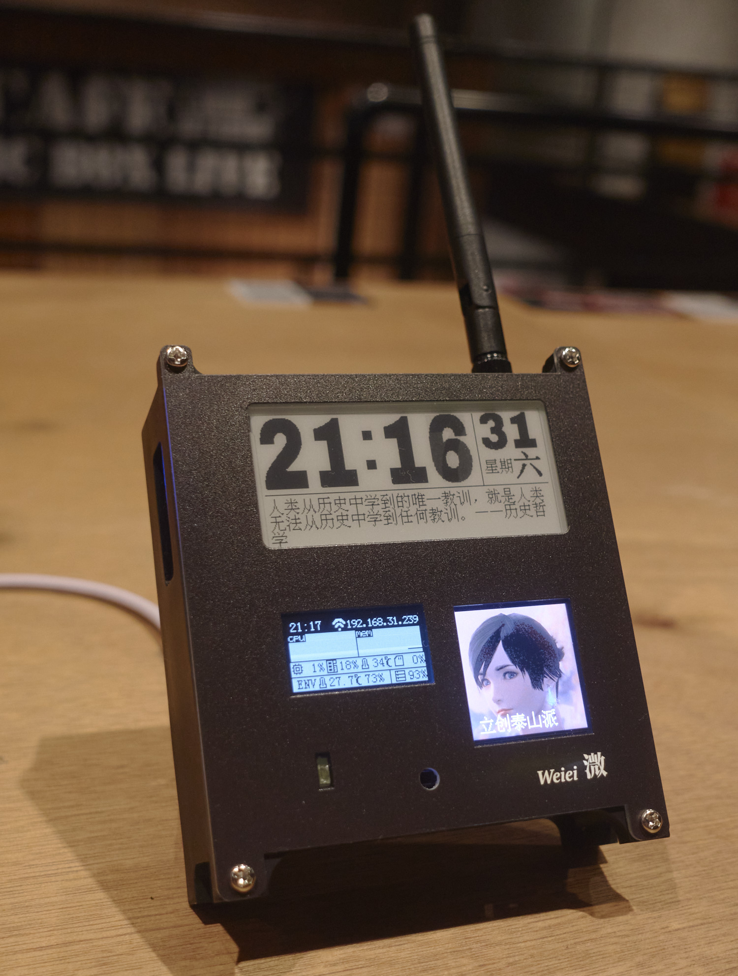
(Powered by JLCPCB panel + gain antenna + PD power module)
Driver Tutorial
1. Modifying the Device Tree
The Taishanpai uses the official Ubuntu image; the system was flashed directly according to the official tutorial.
Because the e-ink screen and LCD screen use SPI communication, while the OLED uses I2C communication, the official system image's device tree doesn't have SPI settings; it needs to be manually modified, and then the core recompiled. This part can be referred to the device tree section of the official tutorial.
First, follow the official tutorial to create an Ubuntu virtual image and download the system SDK. Then, modify the tspi-rk3566-user-v10-linux.dts file located in kernel/arch/arm64/boot/dts/rockchip.
Add a spi3.0 device
spi3: spi@fe640000 {
compatible = "rockchip,rk3066-spi";
reg = <0x0 0xfe640000 0x0 0x1000>;
interrupts = ;
#address-cells = <1>;
#size-cells = <0>;
clocks = <&cru CLK_SPI3>, <&cru PCLK_SPI3>;
clock-names = "spiclk", "apb_pclk";
dmas = <&dmac0 26>, <&dmac0 27>;
dma-names = "tx", "rx";
pinctrl-names = "default", "high_speed";
pinctrl-0 = <&spi3m0_cs0 &spi3m0_cs1 &spi3m0_pins>;
pinctrl-1 = <&spi3m0_cs0 &spi3m0_cs1 &spi3m0_pins_hs>;
status = "disabled";
};
Set status
&spi3{
status = "okay";
pinctrl-names = "default", "high_speed";
// Enable SPI3, specify the pinctrl node and CS chip select pin
pinctrl-0 = <&spi3m1_cs0 &spi3m1_pins>;
pinctrl-1 = <&spi3m1_cs0 &spi3m1_pins_hs>;
//cs-gpios = <&gpio4 RK_PC6 GPIO_ACTIVE_LOW>;
spi_test@0 {
status = "okay";
compatible = "rockchip,spidev";
reg = <0>; //chip select 0:cs0 1:cs1
spi-max-frequency = <48000000>; //spi output clock
//dc_control_pin = <&gpio3 RK_PA7 GPIO_ACTIVE_HIGH>;
pinctrl-names = "default";
//pinctrl-0 = <&spi_oled_pin>;
};
};
Then use ./build.sh kernel to compile the kernel:
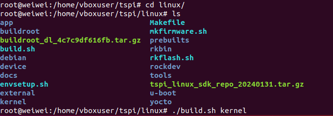
generate kernel/boot.Img, then follow the official tutorial to load the configuration file and flash it.
To use the Python driver
, first install pip3:
`sudo apt install python3-pip`.
Because I tried using the Adafruit Blinka library, but kept getting errors, saying the machine library was missing, I had to write my own driver using the periphery library. My code also uses the pywifi and numpy libraries:
`sudo pip3 install python-periphery`
`sudo pip3 install pywifi` `
sudo pip3 install numpy`
Basic communication methods:
`from periphery import SPI, GPIO
# E-ink screen SPI communication
cs = GPIO('/dev/gpiochip3', 18, "out")
dc = GPIO('/dev/gpiochip3', 2, "out")
rst = GPIO('/dev/gpiochip3', 8, "out")
busy = GPIO('/dev/gpiochip0', 15, "in")
spi = SPI("/dev/spidev3.0", 0, 48000000) # 48MHz SPI pin is SPI3 in the official pin diagram
# OLED screen I2C communication
i2c_bus = "/dev/i2c-2"
i2c = I2C(i2c_bus)`
Then consult the manuals of various screen drivers and write a driver class.
Once the screen control program is written, it can be set to start automatically on boot using crontab:
@reboot cd /home/lckfb/py && sudo python3 tspi.py
code.zip
taishan pi box.step
PDF_Taishanpai Multi-Screen Expansion Board.zip
Altium_Taishanpai Multi-Screen Expansion Board.zip
PADS_Taishanpai Multi-Screen Expansion Board.zip
BOM_Taishanpai Multi-Screen Expansion Board.xlsx
92536
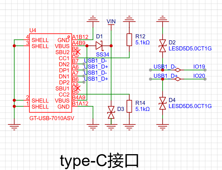
ESP32-based video surveillance system
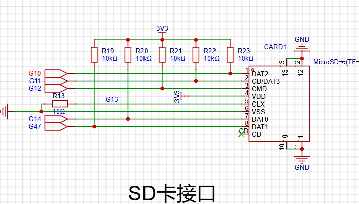
Using an ESP32 as the main controller and an OV2640 to capture images, videos or images can be saved to an SD card and viewed online in real time via Wi-Fi.
This project
uses an ESP32 microcontroller as the main controller and an OV2640 to capture images, saving videos or images to an SD card. Real-time online viewing is also possible via Wi-Fi.
Functionally
, pressing the boot button turns the fill light on or off,
pressing the side button takes and saves
a photo, and the video is transmitted in real-time via UDP. The footage can be viewed on a Python-based host computer, making it suitable for video surveillance.
Project parameters:
ESP32 S3 N16R2 provides Wi-Fi functionality; its large FASH memory allows for ample photo storage even without an SD card;
OV2640 2MP 24p
RGB color fill light;
Hardware notes:
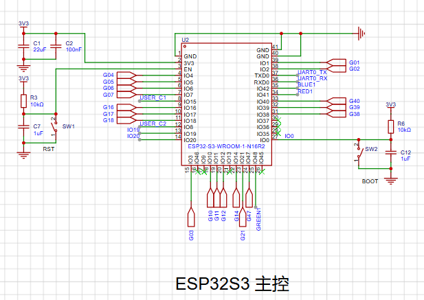
Note that some pins of the ESP32S3 model are for connecting to an external FASH memory and cannot be used for other purposes.

Software code
firmware: micropython
hardware.py
from machine import Pin,PWM
from machine import Timer
import os
import json
import camera
import socket
import network
import time
class SteeringEngine:
def __init__(self):
self.PWN_pin=PWM(8,freq=50,duty_ns=500)#0.5ms-2.5ms
def setangle(self,angle):
duty_ns=int(2000000/180*(angle+90)+500000)
self.PWN_pin.duty_ns(duty_ns)
print(self.PWN_pin.duty_ns(),1/self.PWN_pin.freq())
class LED:
def __init__(self):
self.bottom_pin=Pin(0,Pin.IN,Pin.PULL_UP)
self.bottom_pin.irq(trigger=Pin.IRQ_FALLING,handler=self.press_down_isr)
self.red_pin=Pin(41,Pin.OUT,value=1)
self.green_pin=Pin(48,Pin.OUT,value=1)
self.blue_pin=Pin(42,Pin.OUT,value=1)
self.state = 0
def press_down_isr(self,pin):
self.timer=Timer(-1,mode=Timer.ONE_SHOT,period =10,callback= self.button_check_isr)
def button_check_isr(self,t):
if self.bottom_pin.value()==0:
if self.state==0 :
self.red_pin.value(0)
self.green_pin.value(0)
self.blue_pin.value(0)
self.state = 1
else:
self.red_pin.value(1)
self.green_pin.value(1)
self.blue_pin.value(1)
self.state = 0
class WIFI:
def __init__(self,WLAN_name='',password='Q'):
self.ssid=WLAN_name
self.key=password
self.sta_if = network.WLAN(network.STA_IF)
def connect(self):
if not self.sta_if.isconnected():
start=time.ticks_ms()
print('connecting to network...')
self.sta_if.active(True)
self.sta_if.connect(self.ssid, self.key)
while not self.sta_if.isconnected():
now=time.ticks_ms()
if time.ticks_diff(now, start)>10000:
print('connect WiFi error')
print('connect WiFi ok')
print(self.sta_if.ifconfig()[0])
def(self):
self.sta_if.disconnect()
print('disconnect WiFi ok')
class Camera:
def __init__(self):
try:
camera.init(0, format=camera.JPEG)
except Exception as e:
camera.deinit()
camera.init(0, format=camera.JPEG)
camera.flip(1)
camera.mirror(1)
camera.framesize(camera.FRAME_HVGA)
camera.speffect(camera.EFFECT_NONE)
camera.saturation(0)
camera.brightness(0)
camera.contrast(0)
camera.quality(10)
#10-63 The smaller the number, the higher the quality
def get(self):
return camera.capture()
def retry(self):
try:
camera.deinit()
camera.init(0, format=camera.JPEG)
except :
camera.deinit()
camera.init(0, format=camera.JPEG)
def deinit(self):
camera.deinit()
class UDPsever:
def __init__(self,ip="ipconfig view computer ip",port=9090):
self.s = socket.socket(socket.AF_INET,socket.SOCK_DGRAM,0)
self.ip=ip
self.port=port
def send(self,data):
self.s.sendto(data, (self.ip, self.port))
class Shutter:
def __init__(self,func=lambda : print('')):
self.bottom_pin=Pin(15,Pin.IN,Pin.PULL_DOWN)
self.bottom_pin.irq(trigger=Pin.IRQ_RISING ,handler=self.press_down_isr)
self.func=func
def press_down_isr(self,pin):
self.timer=Timer(-1,mode=Timer.ONE_SHOT,period =10,callback= self.button_check_isr)
def button_check_isr(self,t):
if self.bottom_pin.value()==0:
self.func()
class Hotspot:
def __init__(self):
self.ap_if = network.WLAN(network.AP_IF)
def on(self):
self.ap_if.active(True)
self.ap_if.config(ssid="night-light")
print(self.ap_if.ifconfig()[0])
def off(self):
self.ap_if.active(False)
class Config:
def __init__(self):
if 'config.json' not in os.listdir():
data={
'img_index' : 0,
'data':'123'
}
with open('config.json', 'wb') as file:
json.dump(data, file)
with open('config.json', 'rb') as file:
self.config_dict = json.load(file)
def save(self):
with open('config.json', 'wb') as file:
json.dump(self.config_dict, file)
def __getitem__(self, key):
return self.config_dict[key]
def __setitem__(self, key, value):
self.config_dict[key] = value
self.save()
if __name__=='__main__':
pass
Note: Enter your home Wi-Fi name and password.
Check your computer's IP address through ipconfig.
main.py
from hardware import WIFI,LED,UDPserver,Camera,Config,Shutter,SteeringEngine
import time
import machine
import gc
machine.freq(240000000)
config=Config()
LED()
wifi=WIFI()
wifi.connect()
udp=UDPserver()
camera=Camera()
def take_pic():
file_name=f'img_{config['img_index']+1}.png'
try:
with open(file_name, "wb") as f:
f.write(camera.get())
except Exception as e:
print(e)
else:
config['img_index'] += 1
print('Take a picture')
Shutter(func=take_pic)
s=SteeringEngine()
s.setangle(-90)
while True:
# try:
udp.send(camera.get())
time.sleep(0.2)
print(gc.mem_free()/1024)
# except Exception as e:
# print('err:',e)
# gc.collect()
# camera.retry()
# finally:
# camera.deinit()
host computer code
import socket
import cv2
import io
from PIL import Image
import numpy as np
s = socket.socket(socket.AF_INET, socket.SOCK_DGRAM, 0)
s.bind(("0.0.0.0", 9090))
while True:
data, I


 京公网安备 11010802033920号

 1206B112M251LR


