Project Introduction
This project is a smart car based on the LCSC Skystar GD32 microcontroller. The code is entirely based on the official Skystar example code and includes line following, obstacle avoidance, and Bluetooth remote control functions. You can also learn about the Liangshan School of Smart Cars through the LCSC training camp.
The entire car adopts a modular design, which facilitates component reuse and simplifies soldering for beginners, making it very suitable for beginners learning about smart cars for the first time.
Principle Analysis
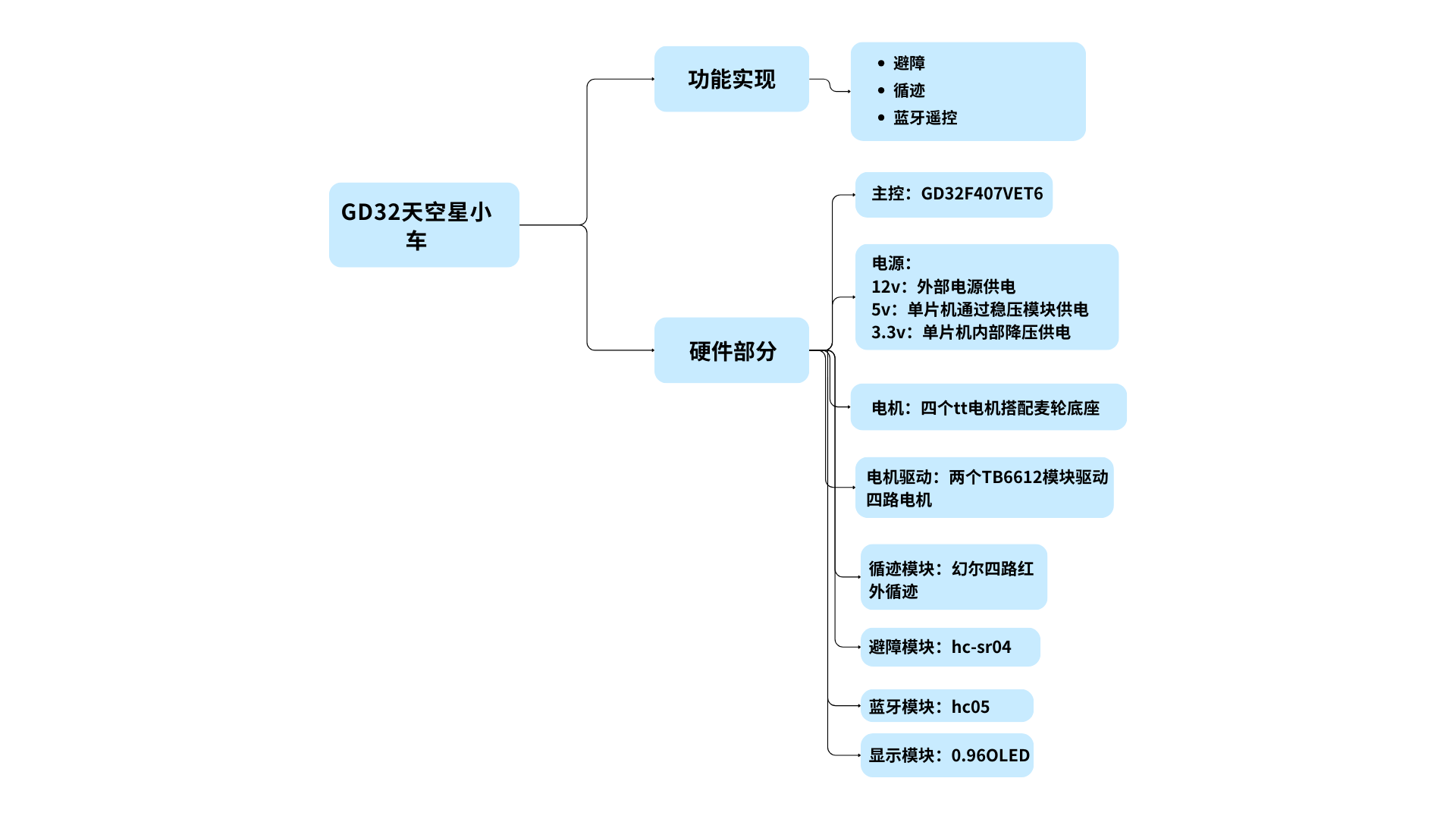
The overall design scheme of the Skystar smart car system is shown in the figure below. The power supply circuit uses a 12V lithium battery, which is stepped down to 5V to power the microcontroller system via a step-down chip. The LCSC Skystar core board is connected to the LED lights, button circuit, obstacle avoidance circuit, line following circuit, Bluetooth remote control circuit (wireless remote control function), buzzer, and motor drive circuit on the smart car expansion board.
Implemented Functions
1. Obstacle Avoidance Mode: When the car encounters an obstacle while moving forward, it can rotate in place to avoid the obstacle. (Template1)
2. Line Following Mode: The car can follow the black line on the ground. (Template2)
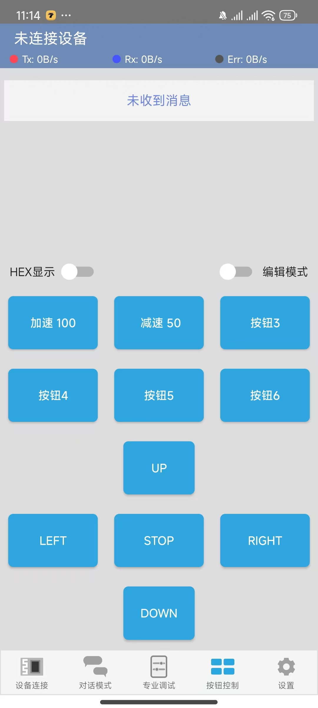
3. Bluetooth Remote Control: Controls the car's forward, backward, left, and right movement, as well as its left and right rotation and stopping. (Template3)
4. Integrated Code Button Switching (Integrated)
Bluetooth button assignments need to be modified manually!!!
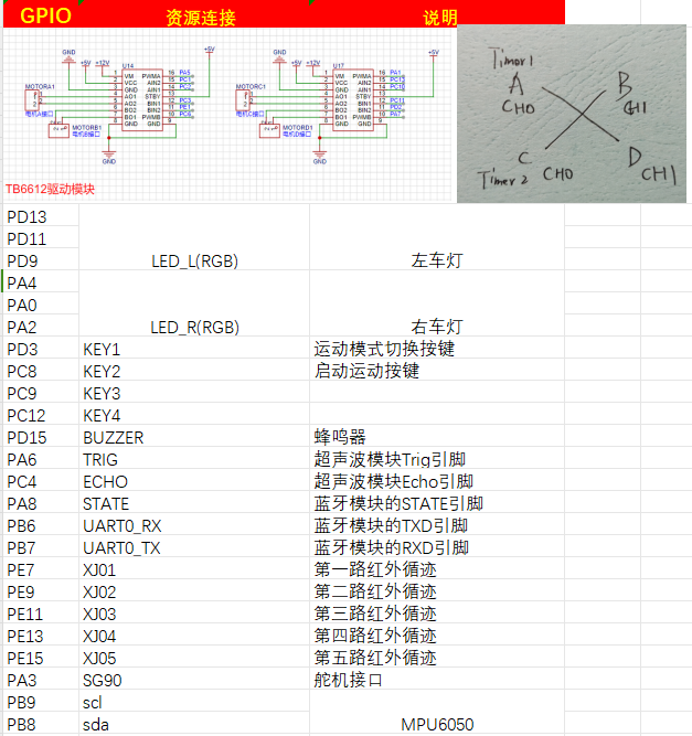
Pin Assignments (module list also included)
Intelligent Car Code Function Description Based on LCSC Skystar GD32
1. LED Lights:
The car has two RGB lights at the front, one on each side.
2. Buttons:
The car's expansion board has four independent buttons, KEY1, KEY2, KEY3, and KEY4, which can be used for starting and switching movement modes. Specific implementations are shown in the code examples.
3. Buzzer:
The car is equipped with a buzzer, which can be used to sound an alarm when encountering obstacles .
4. Ultrasonic Module:
There is an HCSR04 ultrasonic module at the front of the car, which can be used for ultrasonic obstacle avoidance.
5. Motors:
The car has four motors, driven by the TB6612 chip. It can move forward, backward, turn left, turn right, and stop (brake/off). Combined with the timer PWM function, the car's speed can be changed.
6. Tracking:
The car is equipped with 4-channel infrared tracking, which can be used to follow black lines. Five channels are reserved for future modification to a 5-channel tracking capability; this is pre-defined in the code and can be modified as needed.
7. Obstacle Avoidance:
The car can use an ultrasonic module to perform obstacle avoidance.
8. Bluetooth Module:
The car provides a Bluetooth module interface, allowing for wireless remote control via a mobile Bluetooth app.
9. Servo Motor
: The car has a reserved servo motor interface circuit for adding external mechanical clamps.
10. 1.8-inch TFT and 0.96 OLED Display:
The car has reserved interface circuits for 1.8-inch TFT and 0.96 OLED displays. (Note the positive and negative pins of the purchased OLED)
Current Issues: !!
1. The button debouncing function is incorrect; this only affects sensitivity and can be modified manually.
2. The PCB positioning hole size is incorrect and may not fully fit the car base; the positioning holes need to be modified according to the car chassis. (Please add at least one or two M3 screw positioning holes before placing an order, otherwise assembly will not be possible!!!)
3. The buzzer uses a low-level trigger module, and there seems to be a problem with the code, causing it to keep beeping.
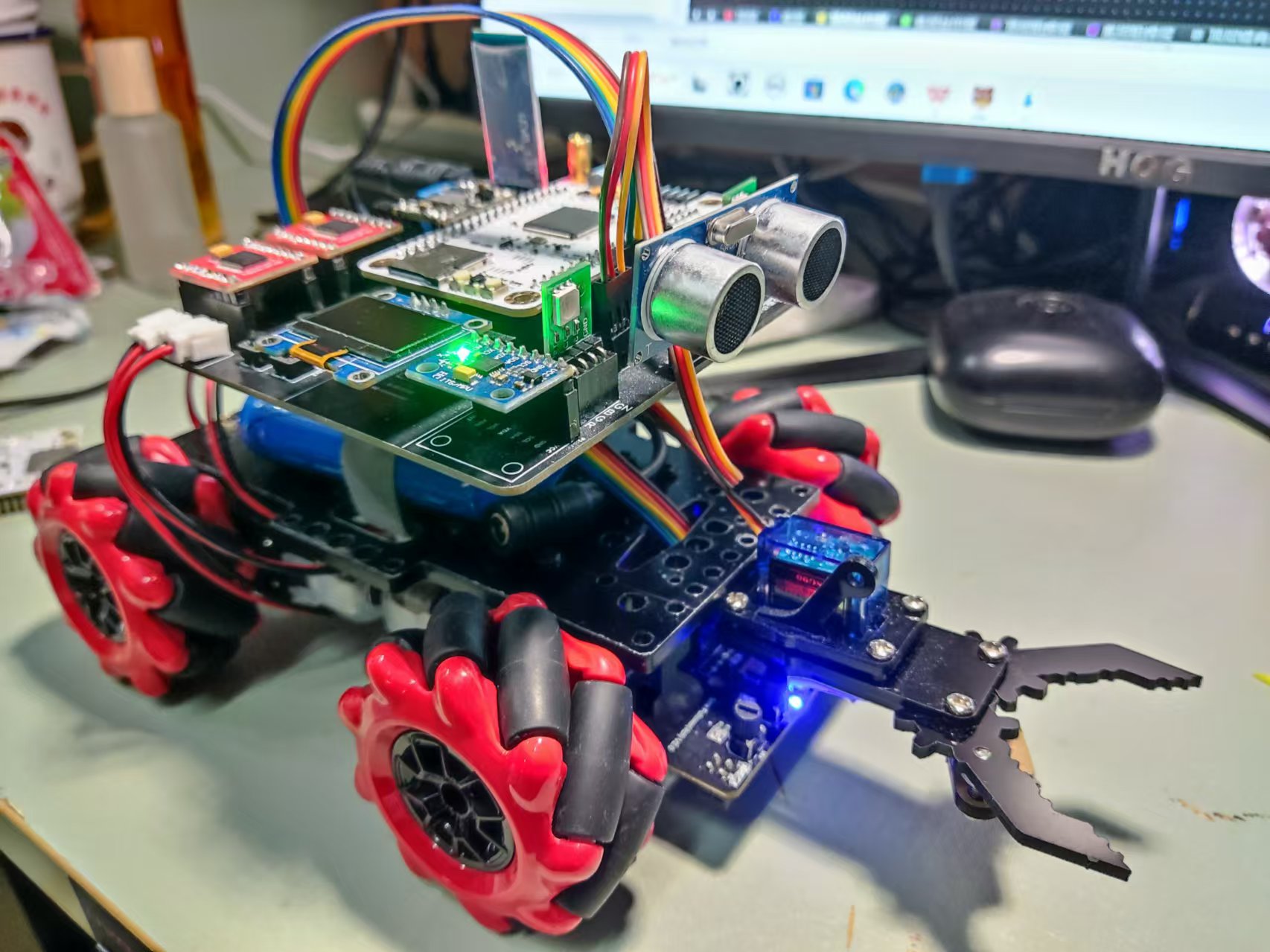
Physical Image
Software Description (Configuration Section)
1. LED (Single Section Only)
Configuration Left RGB Blue LED
void led_gpio_config(void)
{
/* Enable clock */
rcu_periph_clock_enable(LED_BL);
/* Configure output mode as floating mode */
gpio_mode_set(PORT_LED_BL,GPIO_MODE_OUTPUT,GPIO_PUPD_NONE,LED_BL_PIN);
/* Configure as push-pull output 50MHZ */
gpio_output_options_set(PORT_LED_BL,GPIO_OTYPE_PP,GPIO_OSPEED_50MHZ,LED_BL_PIN);
}
Example: Turn off all left/right LEDs
void led_l_off(void)
{
gpio_bit_write(PORT_LED_RL,LED_RL_PIN,RESET);
gpio_bit_write(PORT_LED_GL,LED_GL_PIN,RESET);
`gpio_bit_write(PORT_LED_BL,LED_BL_PIN,RESET);
}
void led_r_off(void)
{
gpio_bit_write(PORT_LED_RR,LED_RR_PIN,RESET);
gpio_bit_write(PORT_LED_GR,LED_GR_PIN,RESET);
gpio_bit_write(PORT_LED_BR,LED_BR_PIN,RESET);
}`
2. Motor Drive and Attitude Control
TB6612 Configuration: Please refer to the example code provided by LCSC for this part and verify that the configuration is complete.
Below are two control methods; you can modify them according to your personal preference.
/******************************************************************
* Function Name: AO_Control
* Function Description: A-port motor control
* Function Parameters: dir: Rotation direction 1 (forward), 0 (reverse) speed: Rotation speed, range (0 ~ per-1)
******************************************************************/
void AO_Control(uint8_t dir, uint32_t speed)
{
if( dir == 1 )
{
AIN1_OUT(0);
AIN2_OUT(1);
}
else
{
AIN1_OUT(1);
AIN2_OUT(0);
}
timer_channel_output_pulse_value_config(BSP_PWMA1_TIMER,BSP_PWMA1_CHANNEL, speed );
}
void SetPWMA(int speed)
{
if(speed>=0)//pwm>=0 (AIN1, AIN2)=(0, 1) forward clockwise
{
AIN1_OUT(1);
AIN2_OUT(0);
timer_channel_output_pulse_value_config(BSP_PWMA1_TIMER,BSP_PWMA1_CHANNEL, speed );
}
if(speed<0)//pwm<0 (AIN1, AIN2)=(1, 0) reverse counterclockwise
{
AIN1_OUT(0);
AIN2_OUT(1);
timer_channel_output_pulse_value_config(BSP_PWMA1_TIMER,BSP_PWMA1_CHANNEL, -speed );
}
if(speed==0)
{
AIN1_OUT(1);
AIN2_OUT(1);
timer_channel_output_pulse_value_config(BSP_PWMA1_TIMER,BSP_PWMA1_CHANNEL, -speed );
}
}
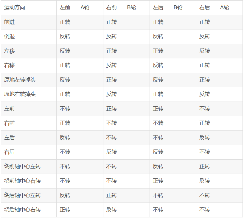
Control Section
/**********************************************************************
* Function Name: motor
* Function Description: Overall Control Section
****************************************************************/
void car_stop(uint32_t speed) //Car stops
{ SetPWMA(0);
SetPWMB(0);
SetPWMC(0);
SetPWMD(0);}
void car_front(uint32_t speed) //Car moves forward
{ SetPWMA(speed);
SetPWMB(speed);
SetPWMC(speed);
SetPWMD(speed);}
void car_back(uint32_t speed) //Car moves backward
{ SetPWMA(-speed);
SetPWMB(-speed);
SetPWMC(-speed);
SetPWMD(-speed);}
void car_left(uint32_t speed) //Car moves left
{ SetPWMA(-speed);
SetPWMB(speed);
SetPWMC(speed);
SetPWMD(-speed);}
void car_right(uint32_t speed) //Car moves right
{ SetPWMA(speed);
SetPWMB(-speed);
SetPWMC(-speed);
SetPWMD(speed);}
void car_on_left(uint32_t speed) //Car turns left in place
{ SetPWMA(-speed);
SetPWMB(speed);
SetPWMC(-speed);
SetPWMD(speed);}
void car_on_right(uint32_t speed) //Car turns right in place
{ SetPWMA(speed);
SetPWMB(-speed);
SetPWMC(speed);}
SetPWMD(-speed);}
void car_front_left(uint32_t speed) //Car moves forward to the left
{ SetPWMA(0);
SetPWMB(speed);
SetPWMC(speed);
SetPWMD(0);}
void car_back_left(uint32_t speed) //Car backs to the left
{ SetPWMA(-speed);
SetPWMB(0);
SetPWMC(0);
SetPWMD(-speed);}
void car_back_right(uint32_t speed) //Car backs to the right
{ SetPWMA(0);
SetPWMB(-speed);
SetPWMC(-speed);
SetPWMD(0);}
void car_front_right(uint32_t speed) //Car moves forward to the right
{ SetPWMA(speed);
SetPWMB(0);
SetPWMC(0);
SetPWMD(speed);}
void car_center_front_left(uint32_t speed) //Car turns left around the center of the front axle
{ SetPWMA(0);
SetPWMB(0);
SetPWMC(-speed);
SetPWMD(speed);}
void car_center_front_right(uint32_t `speed)` // The car turns right around the center of the front axle
{ SetPWMA(0);
SetPWMB(0);
SetPWMC(speed);
SetPWMD(-speed);} `
void car_center_back_left(uint32_t speed)` // The car turns left around the center of the rear axle
{ SetPWMA(-speed);
SetPWMB(speed);
SetPWMC(0);
SetPWMD(0);} `
void car_center_back_right(uint32_t speed)` // The car turns right around the center of the rear axle
{ SetPWMA(speed);
SetPWMB(-speed);
SetPWMC(0);
SetPWMD(0);}
Two control methods are used, and you can choose whichever you prefer.
3. OLED (The onboard OLED is 0.96; 1.8 is not very useful and is only used for learning)
The code will not be shown here. Please directly learn from LCSC's configuration tutorial.
4. The HC-SR04
ultrasonic ranging principle is that the ultrasonic transmitter emits ultrasonic waves and starts timing at the same time. The ultrasonic waves propagate in the air. When they encounter an obstacle, they will send a signal back to the ultrasonic receiver. The ultrasonic receiver stops timing immediately after receiving the signal. At this time, there will be a time t. The speed of ultrasonic waves in the air is 340m/s. The distance to be measured can be calculated by the formula s=340 xt / 200. (Refer to official example code)
HC-SR04 Ultrasonic Ranging Module Working Principle:
Working voltage: DC 5V;
Ranging is triggered by I/O port. The microcontroller sends a high-level signal of at least 10us to the Trig pin of the ultrasonic module to trigger its operation.
The module's transmitting probe automatically sends eight 40KHz square wave signals and automatically detects whether a signal is returned.
If a signal is returned, a high-level signal is output through the Echo pin connected to the microcontroller's I/O port. The duration of the high-level signal is the time from ultrasonic emission to return.
Based on the speed of sound in air being 340 meters per second, the measured distance can be calculated.
5. Five-channel Infrared
Tracking: The tracking principle involves connecting pin 1 of the voltage comparator to a pin on the microcontroller. The I/O is configured as input mode. When pin 1 of the voltage comparator outputs a high level, it indicates that the infrared light is absorbed, a black line is detected, the LED indicator lights up, and the microcontroller I/O reads the high level.
The principle of infrared tracking: It utilizes the reflection of infrared light at different colors to identify and
detect black lines. An infrared emitter emits light to the ground; when the infrared light encounters a white ground surface, it is reflected. The infrared receiver receives the reflected light, and after passing through a voltage comparator, it outputs a low level.
The principle of detecting black lines is that an infrared emitter emits light to the ground; when the infrared light encounters a black ground surface, it is absorbed. The infrared receiver does not receive the reflected light, and after passing through a voltage comparator, it outputs a high level.
#include "bsp_IRtracking.h"
#include "board.h"
#include "stdio.h"
FlagStatus XJ01 = RESET;
FlagStatus XJ02
= RESET; FlagStatus XJ03 =
RESET; FlagStatus XJ04 = RESET;
//FlagStatus XJ05 = RESET;
/****
Function Name: track_gpio_config
Function: Tracking GPIO pin configuration
Parameters: None
Return Value: None
*****/
void track_gpio_config(void)
{
/ Enable clock /
rcu_periph_clock_enable(XJ01_RCU);
/ Configure as input mode pull-up mode /
gpio_mode_set(PORT_XJ01,GPIO_MODE_INPUT,GPIO_PUPD_PULLUP,XJ01_PIN);
/* Enable clock */
rcu_periph_clock_enable(XJ02_RCU);
/* Configure as input mode pull-up mode */
gpio_mode_set(PORT_XJ02,GPIO_MODE_INPUT,GPIO_PUPD_PULLUP,XJ02_PIN);
/* Enable clock */
rcu_periph_clock_enable(XJ03_RCU);
/* Configure as input mode pull-up mode */
gpio_mode_set(PORT_XJ03,GPIO_MODE_INPUT,GPIO_PUPD_PULLUP,XJ03_PIN);
/* /* Enable clock */
rcu_periph_clock_enable(XJ04_RCU);
/* Configure as input mode pull-up mode */
gpio_mode_set(PORT_XJ04,GPIO_MODE_INPUT,GPIO_PUPD_PULLUP,XJ04_PIN);
// / Enable clock/
// rcu_periph_clock_enable(XJ05_RCU);
// / Configure as input mode pull-up mode/
// gpio_mode_set(PORT_XJ05,GPIO_MODE_INPUT,GPIO_PUPD_PULLUP,XJ05_PIN);
}
/****
Function Name: Black_Line_Detection
Function: Black line detection function
Parameters: None
Return Value: None
*****/
void Black_Line_Detection(void)
{
XJ01 = gpio_input_bit_get(PORT_XJ01,XJ01_PIN);
XJ02 = `gpio_input_bit_get(PORT_XJ02,XJ02_PIN);
XJ03 = gpio_input_bit_get(PORT_XJ03,XJ03_PIN);
XJ04 = gpio_input_bit_get(PORT_XJ04,XJ04_PIN);
// XJ05 = gpio_input_bit_get(PORT_XJ05,XJ05_PIN);
}
# **6. Button Definition**
The circuit design principle of an independent button is to connect one end of the button to the microcontroller's I/O port and the other end to ground. When the button is pressed, a low level is read; when the button is released, a high level is read. Note that the I/O port needs to be configured as a pull-up input.`
include "bsp_key.h"
uint8_t uckey=0;
uint8_t Motion_Mode=0;//Motion mode, default is tracking mode
uint8_t Start_Flag=0; //Car start button flag, default is no start, i.e., the car stops
static uint8_t num_flag = 1;//Cycle from 1 to 3, 1, 2, 3 represent obstacle avoidance, tracking, and Bluetooth remote control states
/****
Function Name: key_gpio_config
Function: Independent button GPIO pin configuration
Parameters: None
Return Value: None
*****/
void key_gpio_config(void)
{
/* Enable clock */
rcu_periph_clock_enable(BSP_KEYM_RCU);
rcu_periph_clock_enable(BSP_KEYS_RCU);
/* Configure as input mode pull-up mode */
gpio_mode_set(BSP_KEYM_PORT,GPIO_MODE_INPUT,GPIO_PUPD_PULLUP,BSP_KEYM_PIN); // The button's default state is high, configured as pull-up
gpio_mode_set(BSP_KEYM_PORT,GPIO_MODE_INPUT,GPIO_PUPD_PULLUP,BSP_KEYM_PIN); // The button's default state is high, configured as pull-up
}
/****
Function Name: BSP_KEYM_EXTI_IRQHandler
Function: Interrupt Handling Function
Parameters: None
Return Value: None
*****/
void BSP_KEYM_EXTI_IRQHANDLER(void)
{
if(exti_interrupt_flag_get(BSP_KEYM_EXTI_LINE) == RESET) // Interrupt flag is 0, button pressed
{
if(gpio_input_bit_get(BSP_KEYM_PORT,BSP_KEYM_PIN) == RESET) // Key pressed
{
/ Function of key pressed /
} else { // Key released
/* Function of key released */
}
exti_interrupt_flag_clear(BSP_KEYM_EXTI_LINE); // Clear the interrupt flag
}
}
/****
Function Name: KEY_Read
Function: Key read function
Parameters: None
Return Value: Corresponding key flag
*****/
uint8_t KEY_Read(void)
{
uint8_t key_val=0;
/ First read the level of the key pin. If it is low, the key is pressed. /
if(gpio_input_bit_get(BSP_KEYM_PORT,BSP_KEYM_PIN) == RESET) // Key pressed
{
delay_ms(100); // Debounce delay
if(gpio_input_bit_get(BSP_KEYM_PORT,BSP_KEYM_PIN) == RESET) // Check if the key is pressed again
key_val=1;
}
/* First read the level of the key pin. If it is low, the key is pressed. */
if(gpio_input_bit_get(BSP_KEYS_PORT,BSP_KEYS_PIN) == RESET) // Key pressed
{
delay_ms(100); // Debounce
if(gpio_input_bit_get(BSP_KEYS_PORT,BSP_KEYS_PIN) == RESET) // Check if the key is pressed again
key_val=2;
}
return key_val;
}
/****
Function Name: KEY_Proc
Function: Key press execution program
Parameters: None
Return Value: None
*****/
void KEY_Proc(void)
{
uint8_t key_val=0;
key_val = KEY_Read();
if(key_val != uckey)
uckey=key_val;
else
key_val = 0;
switch(key_val)
{
case 1://1
Motion_Mode^=1;
break;
case 2://2
Start_Flag^=1;
break;
default:
break;
}
}
uint8_t KEY_get(void)
{
if(KEY_Read()==1)
{
num_flag +=1;
if(num_flag ==4)
{
num_flag = 1;
}
}
return num_flag;
}


 京公网安备 11010802033920号

 CD74HCT4040MTG4


