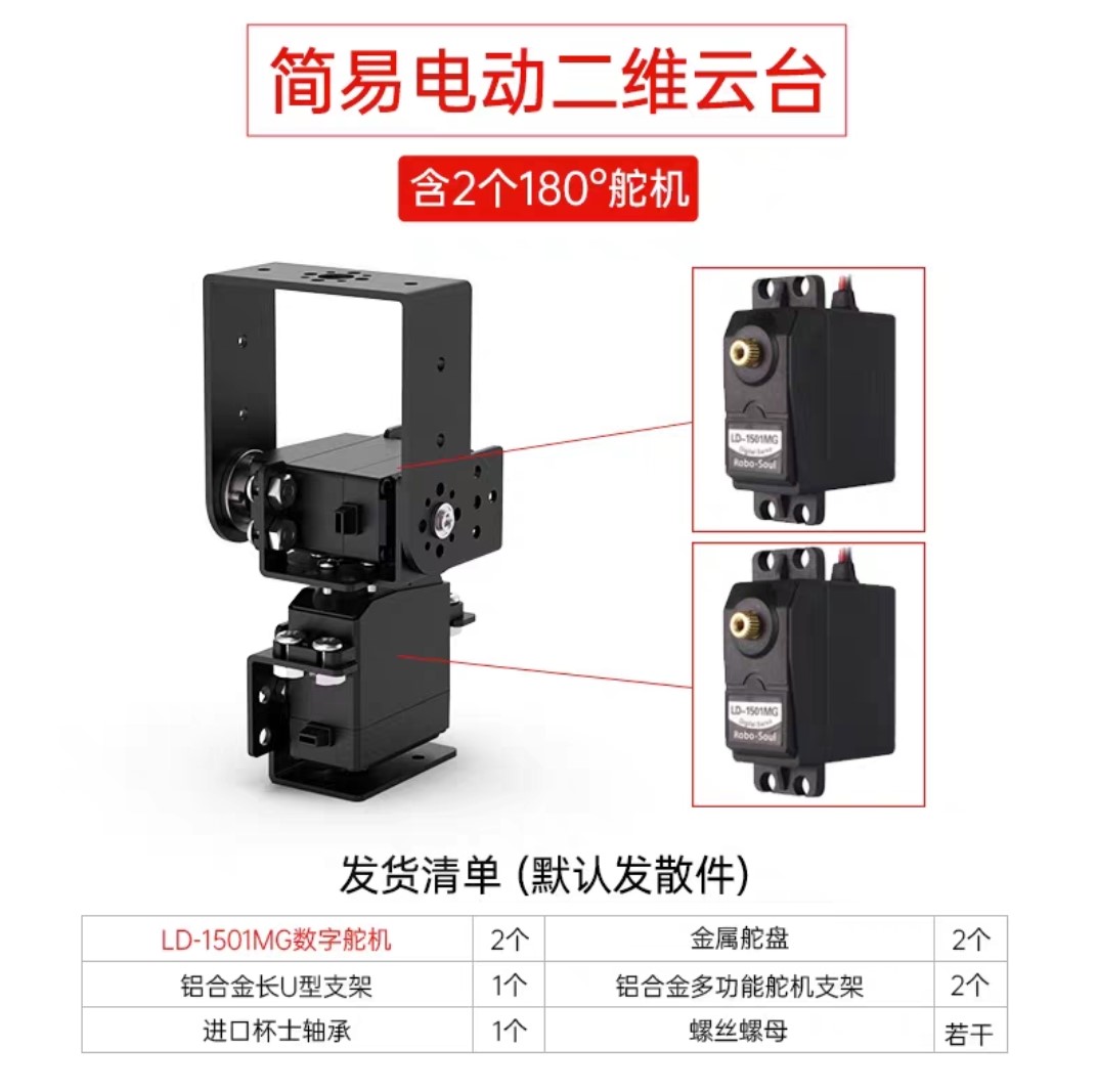
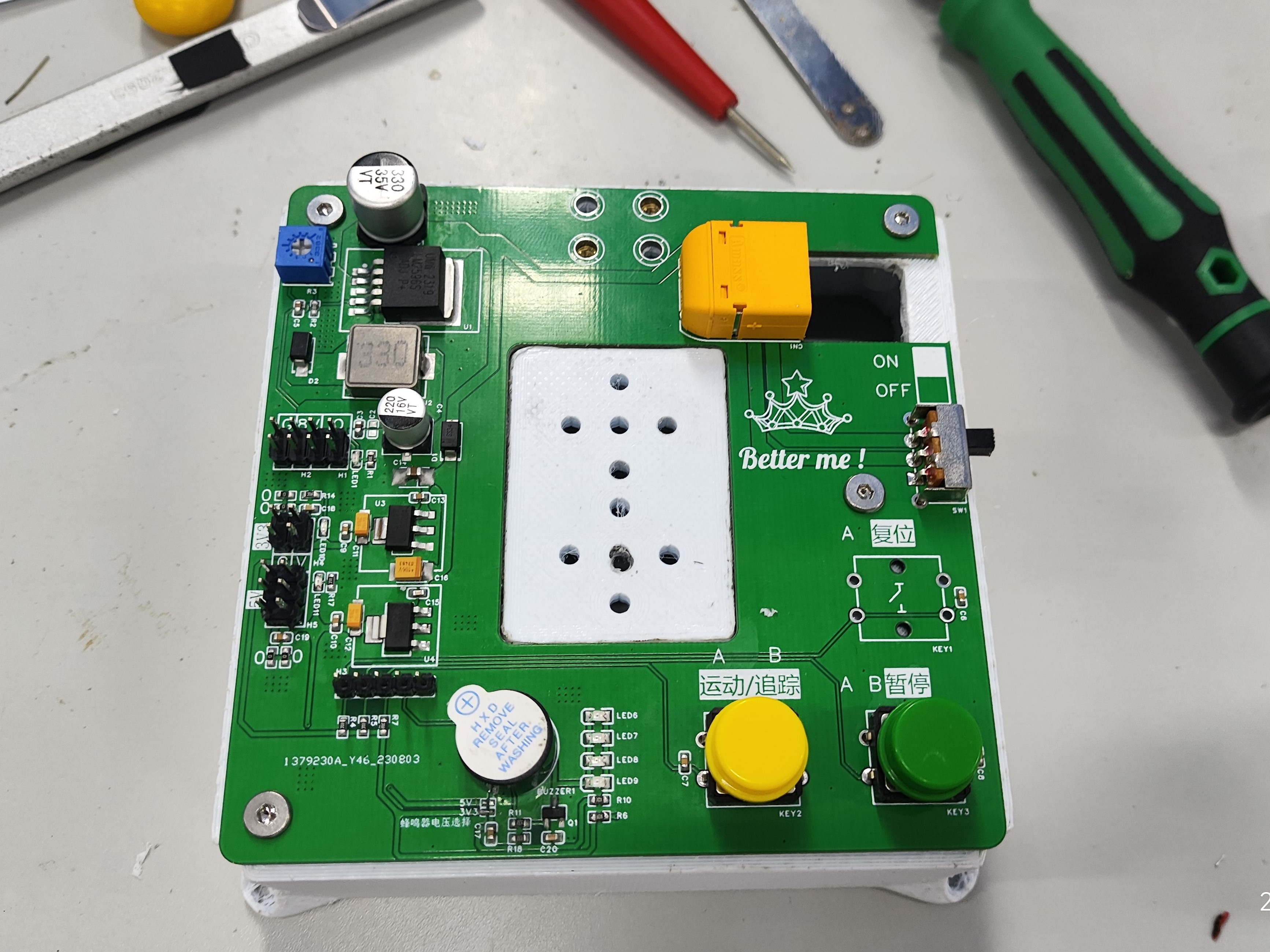
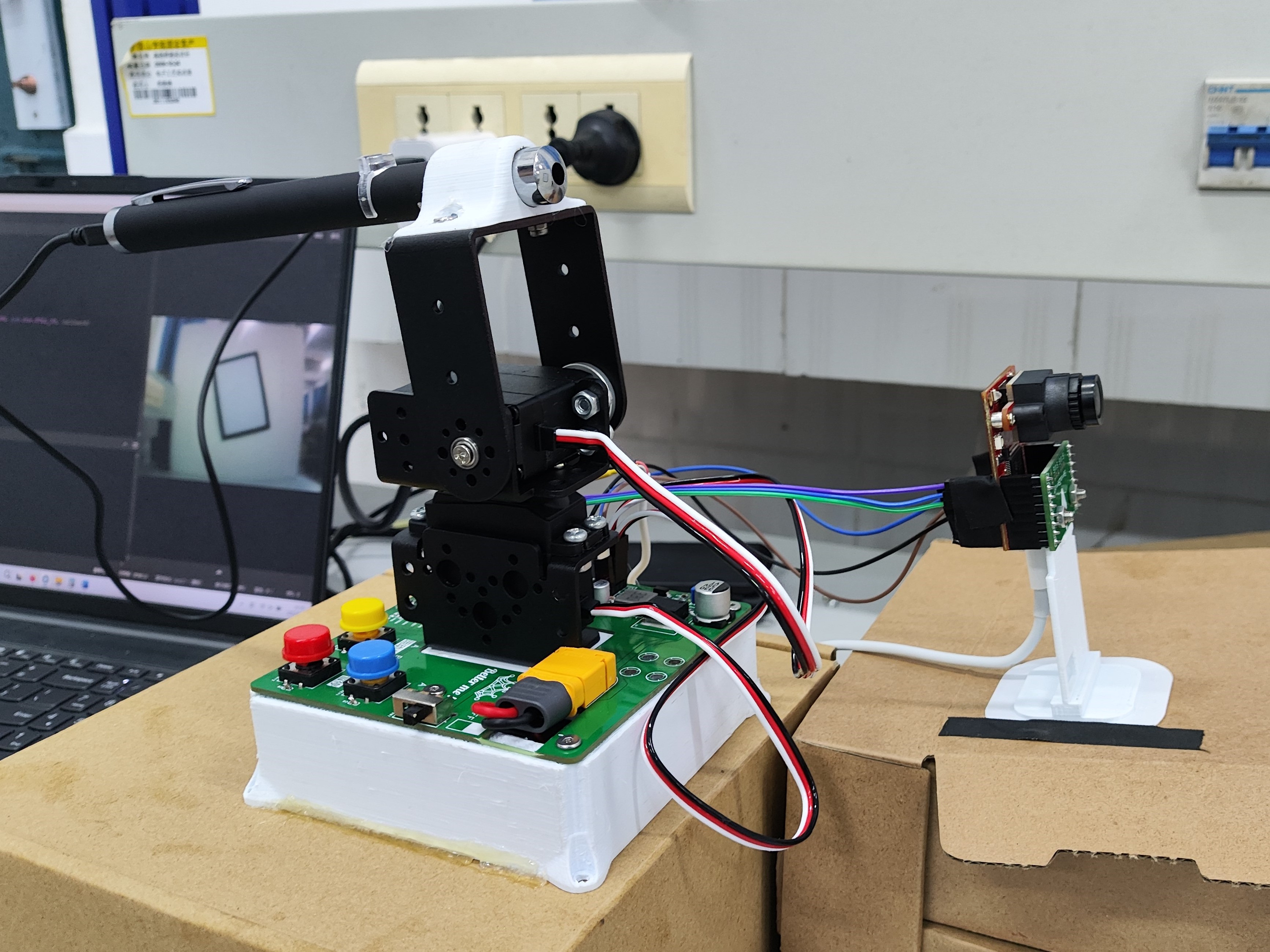
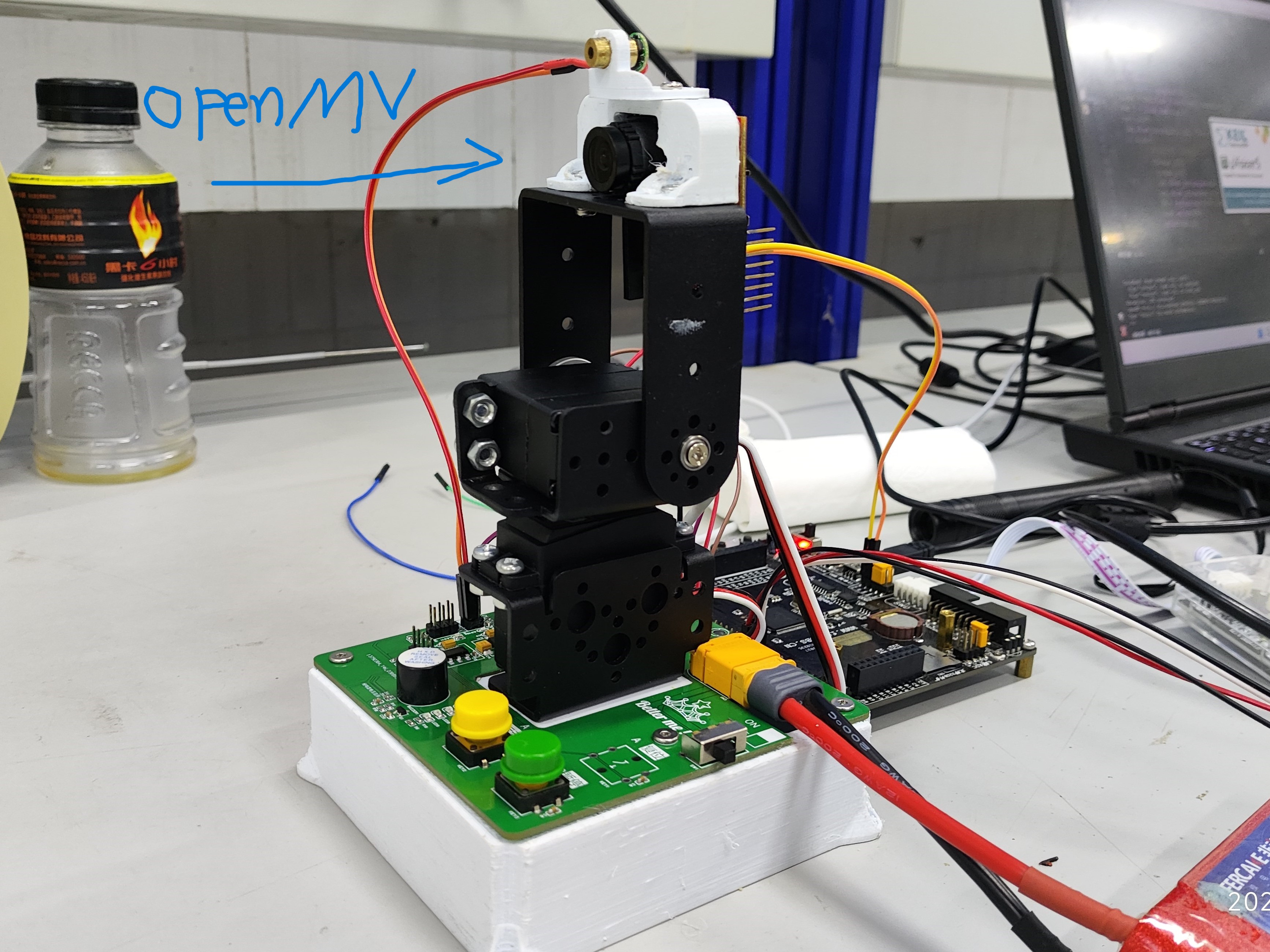
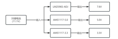
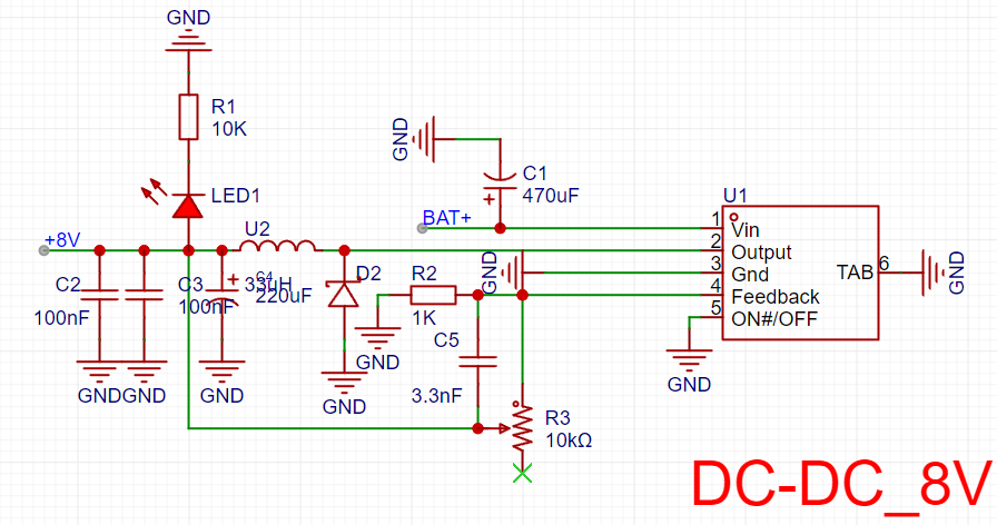
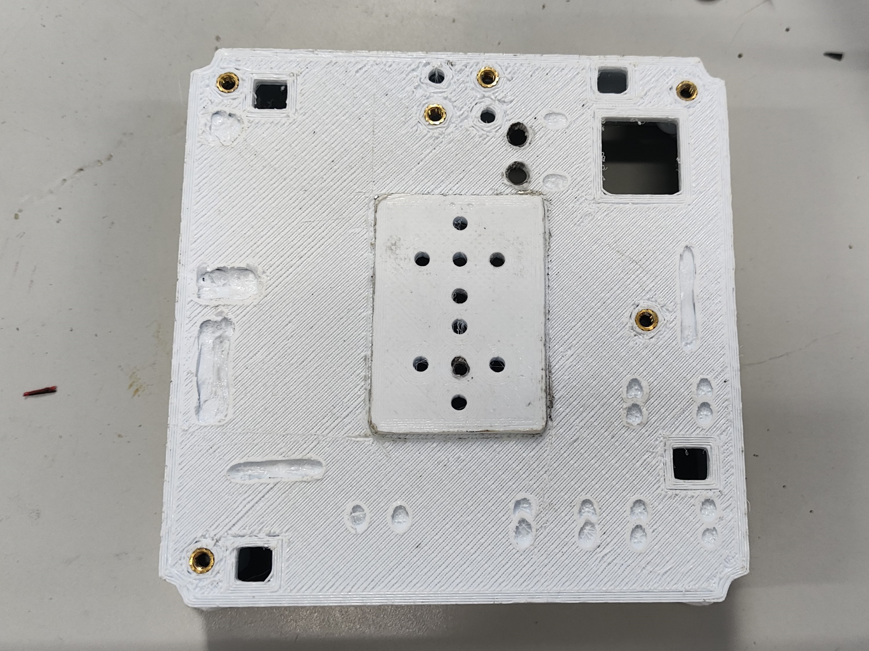
Overview: This PCB
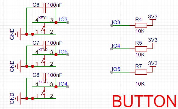
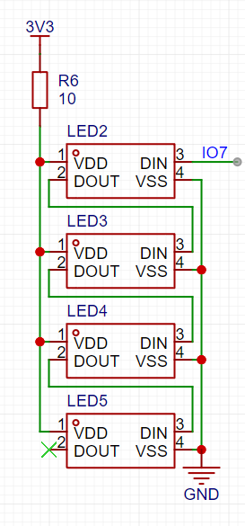
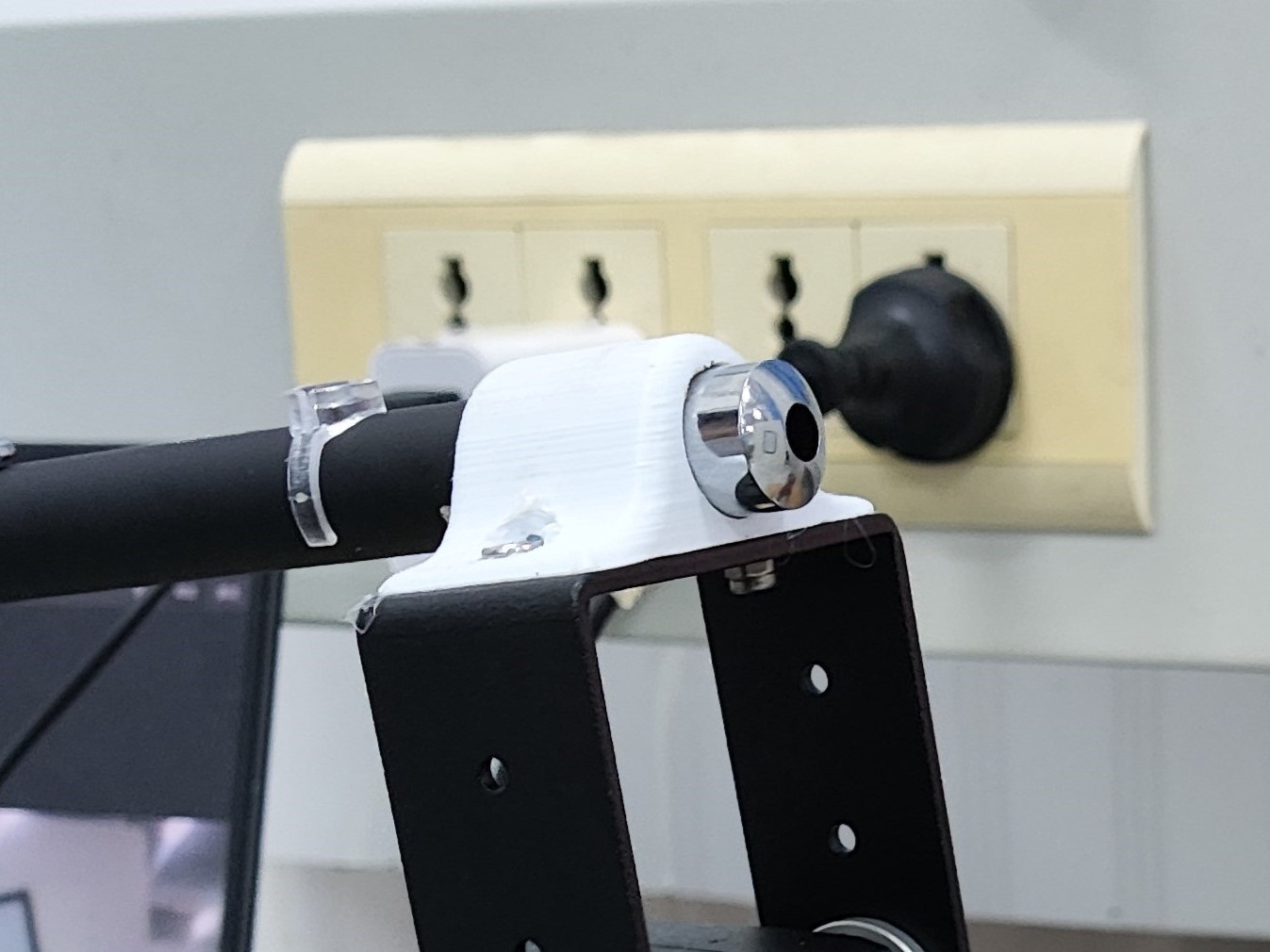
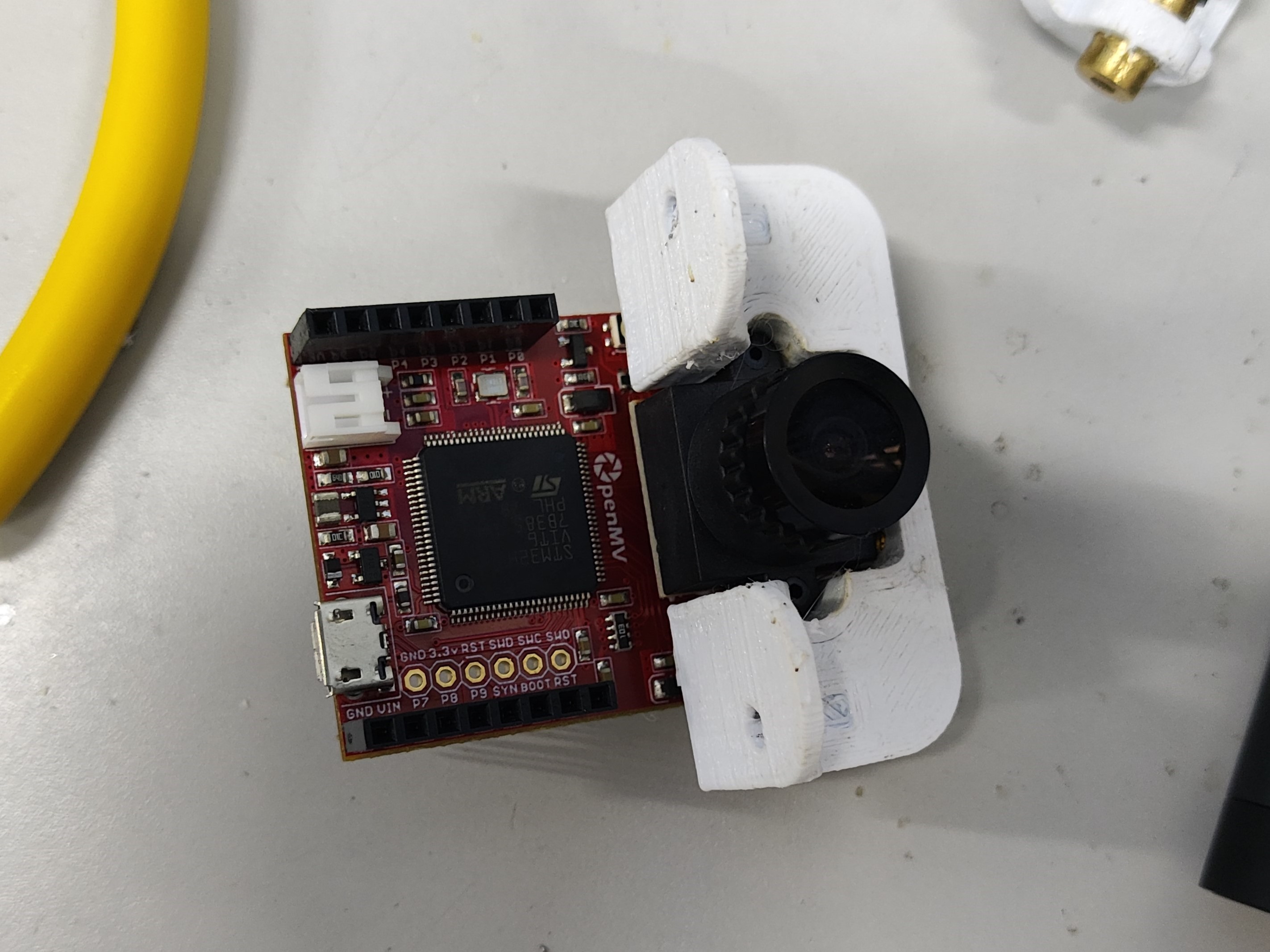
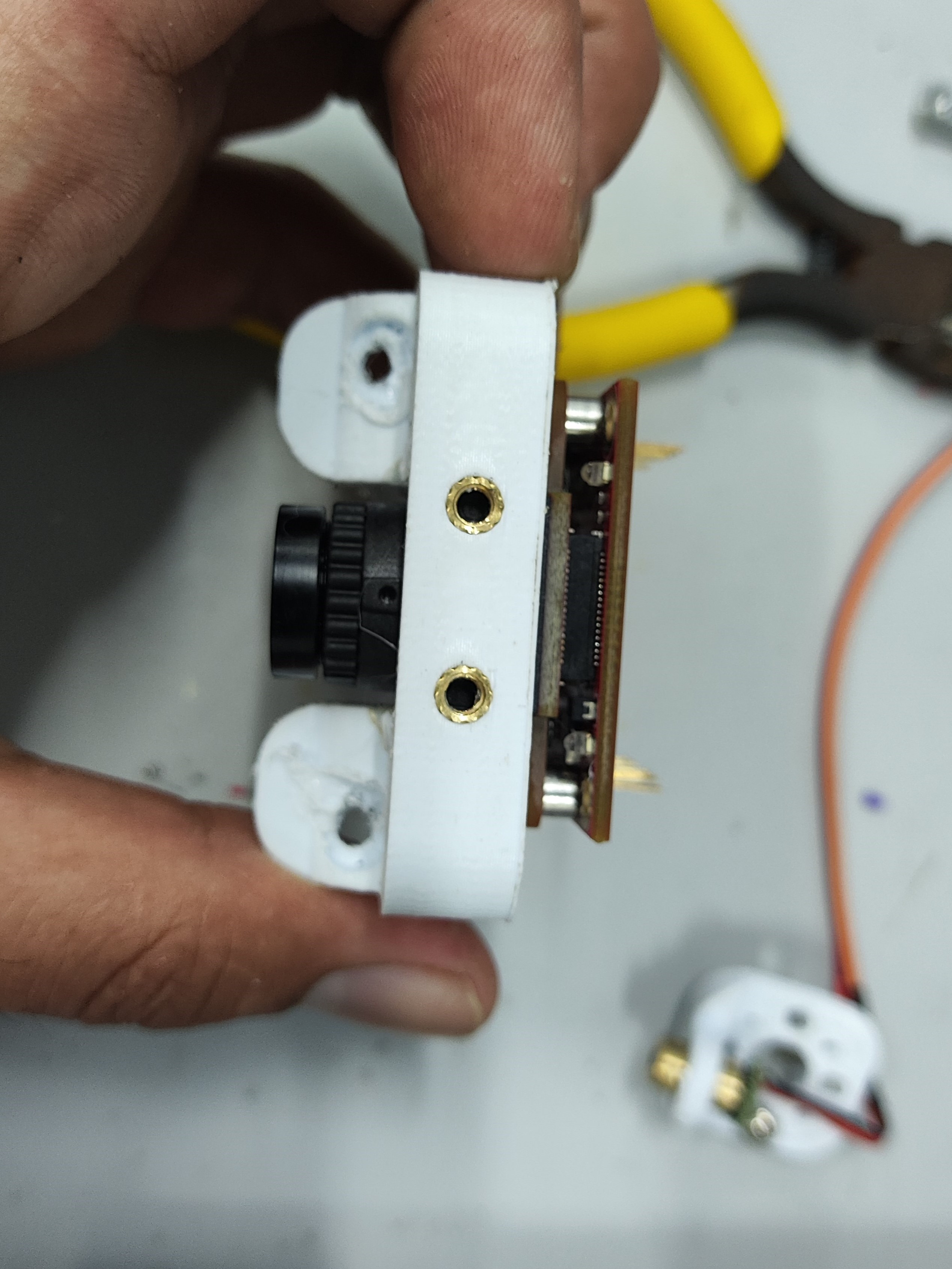
integrates three power supplies: one DC-DC (LM2596S) servo power supply, one 5V LDO (AMS117) OpenMV power supply, and one 3V3 (AMS117) power supply for other modules. It also integrates audible and visual alarms, buttons, and RGB lighting. Suitable for a simple electric 2D gimbal, as shown in Figure B (PCBA), which only requires two buttons. Circuit Module Design: Power supply is a 3S model aircraft battery. DC-DC : The DC-DC chip is LM2596S-ADJ, with a maximum output current of 3A and adjustable voltage, meeting the requirements for simple electric 2D gimbal operation. LDO: The LDO chip is AMS1117, with a maximum output of 1A, easily meeting the power requirements of the OpenMV circuit. The circuit is simple and easy to solder. R15 and R16 are 0Ω connected to a common ground, protecting the OpenMV from servo operation. Other Functional Module Design: Button Module: C6, C7, and C8 are for hardware debounce. Buttons are pulled up by default, and the level is low when pressed. The buzzer in the audible and visual alarm module is an active buzzer. In the design, the buzzer is connected in parallel with the LED, so only one IO needs to be controlled to achieve the audible and visual alarm function. R8 and R9 are shorting positions for 3V3 and 5V power supply, respectively; short one according to your needs. The RGB module design is purely for fun. If you want to use this, please choose a transparent material for the base printout, and place the RGB on the bottom layer of the PCB. The screw holes on the A and B device bases are injection-molded hot-melt copper nuts embedded after printing (some holes are designed relatively small, and the nuts contain printing material; the hole diameter should be enlarged before use). The final effect is excellent and looks very nice. Also, since some PCBAs are through-hole components, some space needs to be left on the printout (this was not considered or not planned during the design). Holes were drilled in the PCBA, and then a soldering iron was applied. For device A—the laser pointer— the laser pointer diameter is 14mm, which is perfect for fixing and also allows for easy removal. However, the distance between the two holes for mounting to the pan-tilt head is a bit too close; it should be increased by 2-3mm. The design was based on the simple electric 2D pan-tilt head 3D file provided by the vendor (blame me again). Device B - the OpenMV mounting bracket directly mounts the OpenMV camera; be careful when using it! If it doesn't fit, use a soldering iron to gently warm it up, but don't use force! However, the distance between the two holes for mounting to the pan-tilt head is a bit too close; it should be increased by 2-3mm. The design was based on the simple electric 2D pan-tilt head 3D file provided by the vendor (blame me again). An embedded injection-molded nut facilitates the next step of laser light installation. Device B - the laser light mounting bracket was initially designed to be mounted directly on the pan-tilt head, but later the space was given to the OpenMV, so it's now mounted above the OpenMV. Summary : 1. Prepare equipment in advance or immediately. We only received the OpenMV at noon on August 4th, resulting in insufficient development and debugging time, which was a huge loss. 2. We didn't conduct extensive testing before packaging. Before packaging, we needed to test in different locations and under different light intensities; we only tested it once, which was a huge loss! 3. Health is very important! During the days of the competition , I stayed up all night, mainly because I had nothing to work on and couldn't make any progress. The PCB design was completed on the first night of the competition. That night, around 3 or 4 AM, a small dog knocked on the door, then went out and barked in the hallway—something's up. There was also a large bug, about 5 centimeters long, covered in legs—creepy, but I didn't take a picture. The video shows the RGB testing, the appearance of device A and device B, and the little dog.


 京公网安备 11010802033920号

 240-0324-15SCG8J7-18L


