of the dc_redstone network clock, with an upgraded core and added peripherals.
uses the Espressif ESP32-S3-WROOM-1-N16R8 module, which utilizes the ESP32-S3 SoC with 8MB PSRAM and 16MB FLASH. The ESP32-S3 supports 2.4GHz Wi-Fi and BLE5 low-power Bluetooth, is powered by an Xtensa® 32-bit LX7 dual-core processor, and boasts a rich array of peripheral interfaces and GPIOs. Peripherals
(CH340), and an ESP USB .
has currently tested all peripherals except the microphone.
The code is open-source on GitHub, but it's poorly written.
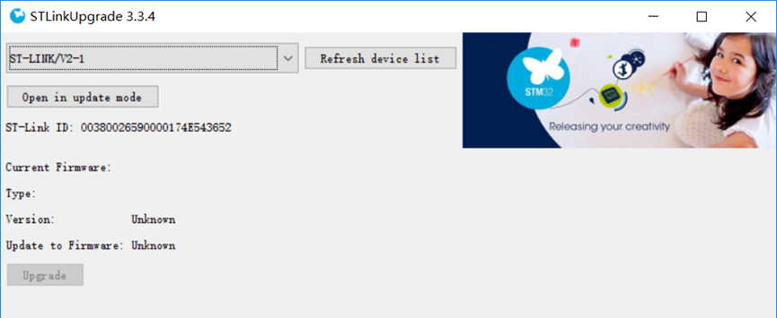
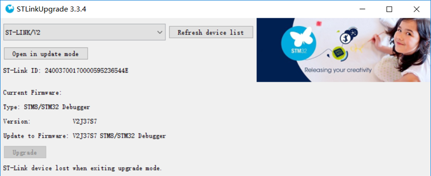
This is a universal ST-LINK adapter that uses an off-the-shelf casing, making it inexpensive.
Learning to design and build a digital voltmeter and ammeter is highly beneficial for improving one's professional skills. This project, undertaken with guidance from engineers at LCSC and Chipone Technology, as well as experts in the WeChat group, resulted in the creation of a simple digital voltmeter and ammeter. Sincere thanks are extended to all of them.
I. Design Background
Learning to design and build a digital voltmeter and ammeter is highly beneficial for improving one's professional skills. This simple digital voltmeter and ammeter project covers multiple aspects, including microcontroller circuit design and implementation, signal acquisition and processing circuit design, user interface development and optimization, and product appearance design. It integrates knowledge from multiple fields such as electronics, microcontroller programming, circuit design, and industrial design. This introductory digital voltmeter and ammeter project is very suitable for beginners in electronics and those who want to learn more about microcontroller applications. This project was completed under the guidance of engineers from LCSC, Chipsource, and experts in WeChat groups. Sincere thanks are extended to all the experts involved. This project has the following highlights:
It adopts a core board plus expansion board design concept, making learning simpler and exploration more in-depth;
the core board uses the domestic Wuhan Chipsource Semiconductor CW32 as the main controller, while also being compatible with other similar development boards; however, the CW32 has advantages.
The project is highly comprehensive and practical, and can be used as a desktop instrument after completion;
the project has abundant learning materials, including circuit design tutorials, PCB design, code programming learning, and training for engineers' debugging abilities.
II. Selection
1. MCU Selection Analysis

Clearly define project requirements: Understand the required computing power, including clock speed, processor core type, and whether a floating-point unit is needed.
Identify the required I/O ports and important peripherals, such as the ADC peripheral. Since this is a development board project, the main purpose is debugging and learning; therefore, there are no strict limitations on the number of I/O ports, i.e., cost issues are not considered.
Key advantages of CW32 in this project:
Wide operating temperature range: -40~105℃;
Wide operating voltage range: 1.65V~5.5V (STM32 only supports 3.3V systems)
; Strong anti-interference: HBM ESD 8KV; All ESD reliability reaches the highest international standard level (STM32 ESD 2KV);
Project focus - Better ADC: 12-bit high-speed ADC, achieving ±1.0LSB INL 11.3ENOB; Multiple Vref reference voltages... (STM32 only supports VDD=Vref);
Stable and reliable eFLASH technology.
2. Power Supply Circuit

: This project uses an LDO as the power supply. Considering that most voltmeter products are used in industrial scenarios with 24V or 36V power supplies, the SE8550K2 with a maximum input voltage of up to 40V was selected as the power supply.
3. Voltage Sampling Circuit : The voltage
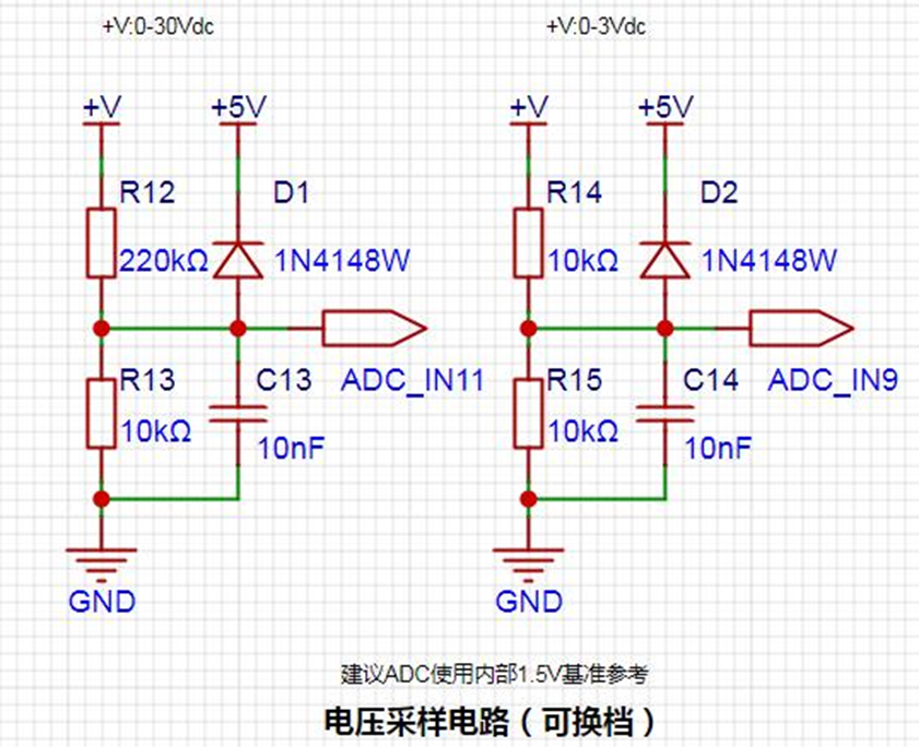
divider resistors in this project are designed to be 220K+10K, therefore the voltage division ratio is 22:1 (ADC_IN11).
The voltage divider resistor selection
is designed to measure the maximum voltage value; for safety reasons, this project uses 30V (the actual maximum display can be 99.9V or 100V).
The ADC reference voltage is 1.5V in this project, and this reference voltage can be configured through the program.
To reduce the power consumption of the sampling circuit, the low-side resistor (R13) is usually chosen as 10K based on experience.
Then, the high-side resistance of the voltage divider resistor can be calculated using the above parameters.
The required voltage division ratio is calculated, i.e., the ADC reference voltage. The input voltage is designed; using known parameters, 1.5V/30V = 0.05 can be calculated.
The high-side resistance is calculated as the low-side resistance/voltage division ratio; using known parameters, 10K/0.05 = 200K can be calculated.
A standard resistor is selected: a resistor slightly higher than the calculated value of 200K is chosen. We usually choose E24 series resistors; therefore, in this project, 220K, which is greater than 200K and closest to the calculated value, is selected.
If, in actual use, the voltage to be measured is lower than 2/3 of the module's design voltage (66V), the voltage divider resistor can be replaced and the program modified to improve measurement accuracy. The following example illustrates this:
Assuming the measured voltage is no higher than 24V and other parameters remain unchanged,
calculations show 1.5V/24V = 0.0625, 10K/0.0625 = 160K. 160K is a standard E24 resistor and can be directly selected, or a higher value 180K can be chosen with some redundancy.
If, in actual use, the voltage to be measured is higher than the module's 99V design voltage, a different resistor can be selected. To achieve a wider voltage measurement range, one can choose to replace the voltage divider resistor or modify the reference voltage. The following example illustrates this:
Assuming the measured voltage is 160V, the solution is to increase the voltage reference to expand the range.
Given that the voltage division ratio of the selected resistor is 0.0145, we can calculate 160V * 0.0145 = 2.32V using the formula. Therefore, we can choose a 2.5V voltage reference to expand the range (increasing the range will reduce accuracy).
Considering the potential fluctuations in the measured power supply, a 10nF filter capacitor is connected in parallel with the low-side voltage divider resistor to improve measurement stability.
Range switching:
In this project, an additional voltage sampling circuit was added. Therefore, we can discuss the significance of range switching for improving measurement accuracy. Multimeters often have multiple range settings for more accurate measurements. By adjusting different ranges, the optimal measurement accuracy of the measured point within the corresponding range can be obtained.
This project requires a combination of hardware and software to achieve this function. When we first use the ADC_IN11 channel mentioned earlier to measure voltages below 30V... If the measured voltage is within 0~3V, use the ADC_IN9 channel for measurement. In this case, the measurement accuracy is greatly improved due to the reduced voltage division ratio.
There are many ways to implement range switching; the development board design provides more design possibilities.
4. Current Sampling Circuit

Note: When learning, please do not solder R0!!!
The design analysis
for this project involves a sampling current of 3A, and the selected sampling resistor (R0) is 100mΩ.
The selection of the sampling resistor mainly considers the following aspects:
the maximum value of the pre-designed measurement current;
the voltage difference caused by
the 3A current sensing resistor in this project; and the power consumption of the current sensing resistor, which should generally not exceed 0.5V. A suitable package should be selected based on this parameter. Considering the power consumption (temperature) issue under high current, a 1W package resistor was chosen
. The voltage amplification factor across the current sensing resistor is 1 since no operational amplifier is used in this project.
The current sensing resistor value can then be calculated using the above parameters.
Since no amplifier circuit is used in this project, a larger sampling resistor is needed to obtain a higher measured voltage for measurement. However,
considering that a larger resistor will result in a larger voltage difference and higher power consumption, an unlimited selection of a larger resistor is not possible.
A 1W package resistor was chosen in this project, corresponding to a power consumption rise of 1W.
Based on the above data, a 100mΩ current sensing resistor was selected. According to the formula, 3A * 100mΩ = 300mV, 900mW.
To handle different usage environments, especially high-current scenarios, resistor R0 can be replaced with constantan wire or a shunt, allowing for selection based on the specific application. For safety and educational purposes, this project will not delve into measurements exceeding 3A, but the principle remains the same.
5. Digital Tube Display
This project uses digital tubes as the display unit.

In this project, actual testing showed that the current-limiting resistors (R1~R6) for the digital tubes were configured to 300Ω, resulting in good visibility and a soft, non-glaring brightness.
Strictly speaking, the current-limiting resistors should be added to the segments; adding them to the digits would affect the display effect. In our actual design, we added them to the digits, saving a few resistors, but the impact on the display is not significant, so we still added them to the digits.
When calculating the current required for the digital tubes,

it is important to ensure that the selected MCU has sufficient current-source/current-sinking capabilities.

6. TL431 Circuit Design for Voltage Measurement and Calibration:

This project adds an extra TL431 circuit to provide a 2.5V reference voltage. This can be used to provide an external voltage reference for the chip to calibrate the AD converter. From a product design perspective, due to the inherent ADC performance advantages of the CW32, this circuit is not necessary. This circuit is designed on the development board for learning related application principles.
The TL431 is a relatively "old" device, a classic, and widely used one, still found in many electronic products.
TI defines it as a "Precision Programmable Reference." On the first page of the references, we can focus on several key characteristics:
Precision: Precision indicates that its output voltage is very accurate. At room temperature, the measured voltage on the board is 2.495V. Compared to common Zener diodes, the accuracy is vastly different. In the application circuit diagram, the TL431 is represented by a Zener diode symbol.
Adjustable Output Voltage: The adjustable output voltage is between Vref and 36V. In this project, we use the output Vref voltage, which is approximately 2.5V. Therefore, we use 2.5V in the description, which is approximately equal to 1mA.
Sinking current capability: This refers to how much current the output voltage pin can provide, which is greatly related to the resistance value (R16) in the application circuit. It should not be less than 1mA. If there is no need for sinking current, do not design the current too high, causing unnecessary power consumption.
III. Optimization and Debugging
Accuracy Optimization: Appropriate resistors, capacitors, and other components can be selected, and the sampling rate and resolution of the ADC can be optimized to improve the measurement accuracy of voltage and current.
Stability Optimization: The power management circuit and reverse connection protection circuit can be optimized to ensure stable operation of the system under various working environments.
Software Debugging: The software can be debugged and optimized using debugging tools to ensure the correctness and stability of data acquisition, processing, and display functions.
Data Analysis: In special applications, the algorithm can be modified or selected according to the actual signal interference.
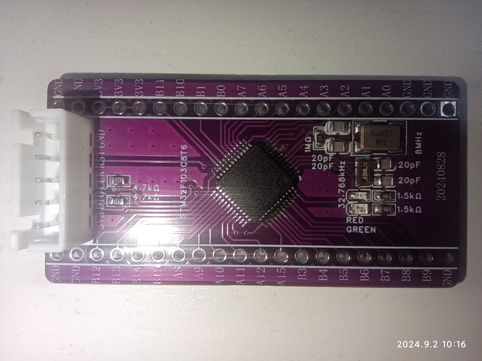
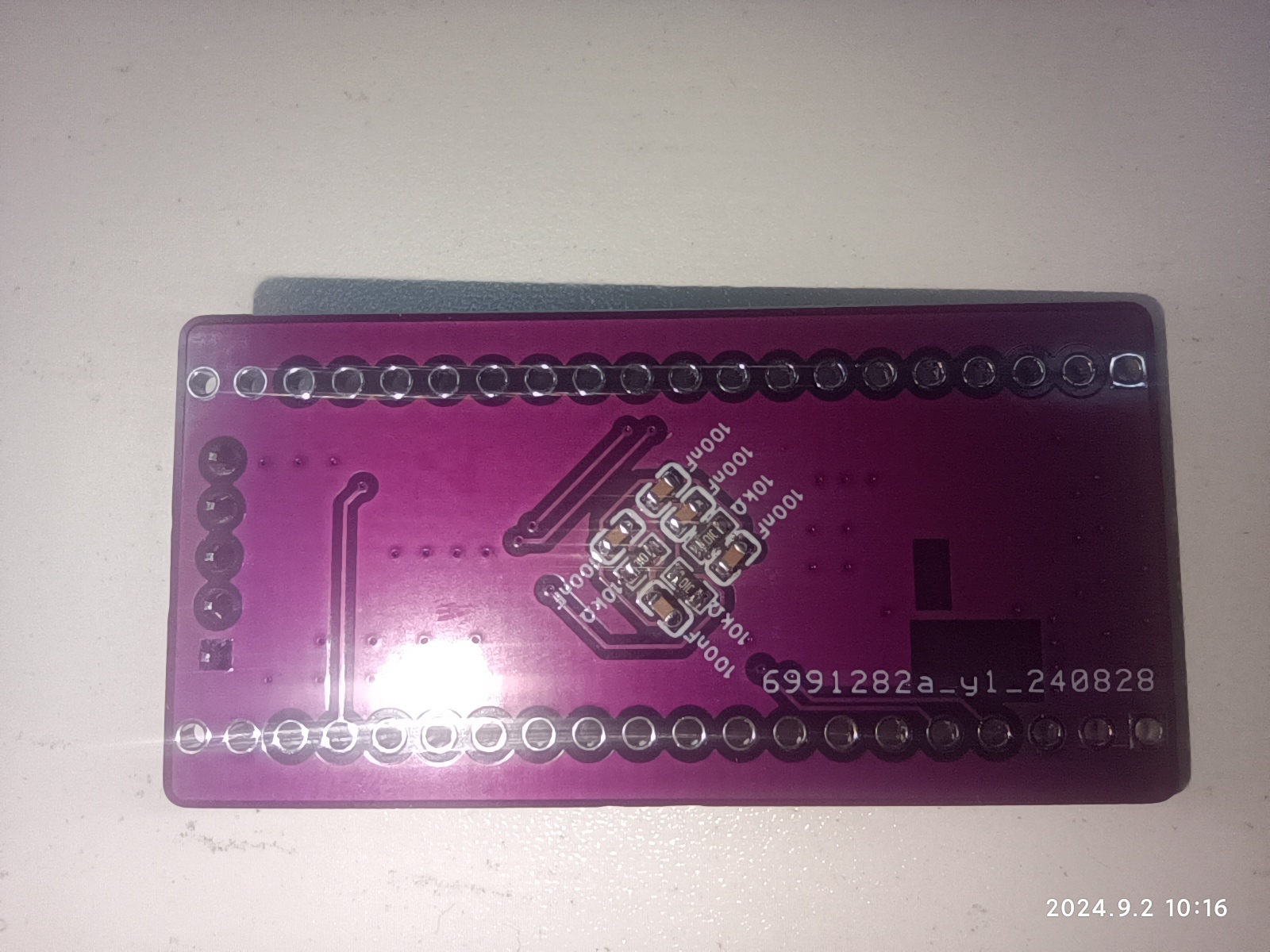
This is a minimum system board for the STM32F103C8T6, with few components, primarily used for learning and verification.
This project's functional
design is a minimum system board based on the STM32F103C8T6 microcontroller; all GPIO ports except PC13 are brought out;
physical diagram.
PDF_STM32F103C8T6 Minimum System Board.zip
Altium_STM32F103C8T6 Minimum System Board.zip
PADS_STM32F103C8T6 Minimum System Board.zip
BOM_STM32F103C8T6 Minimum System Board.xlsx
92559
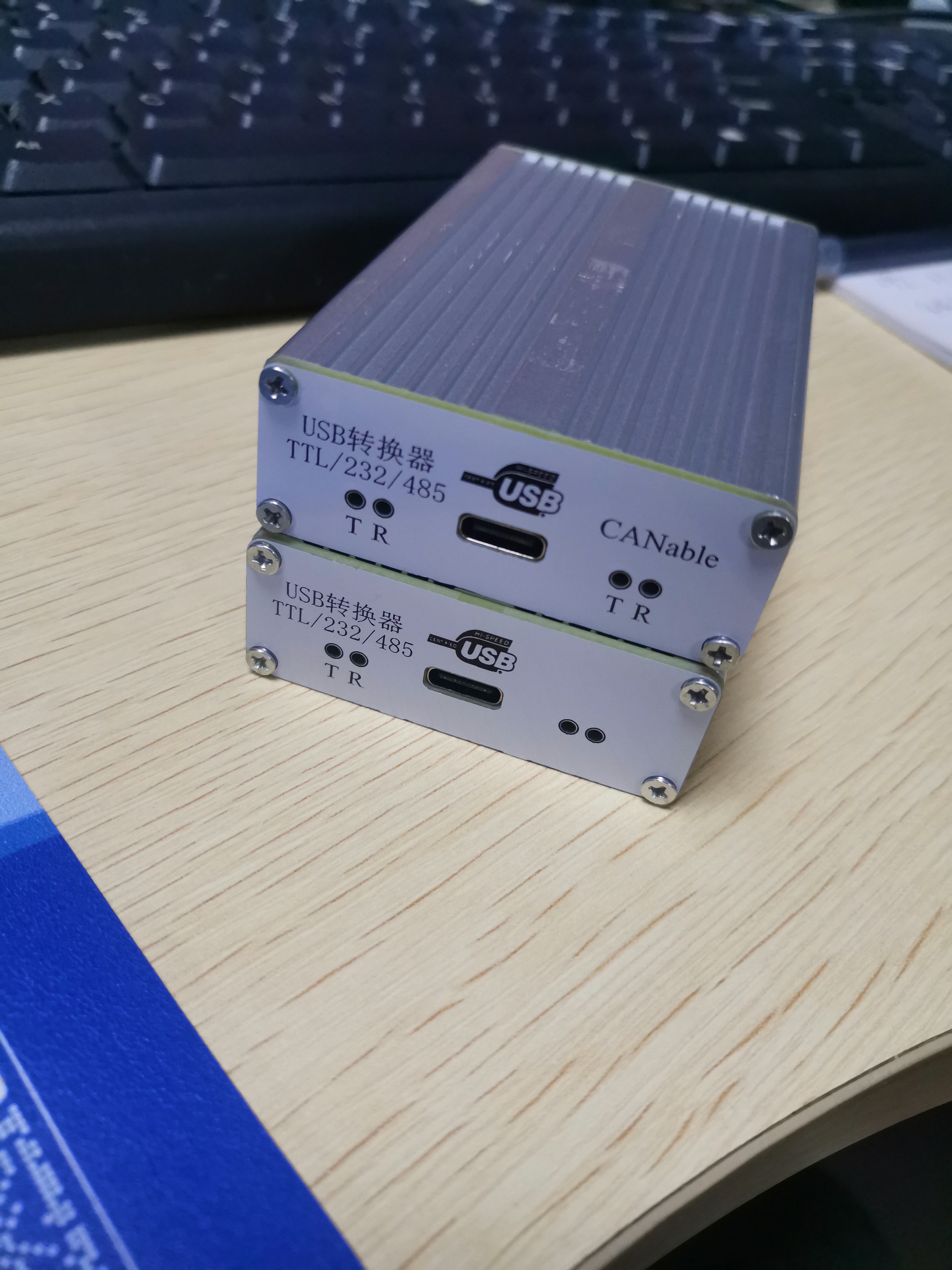
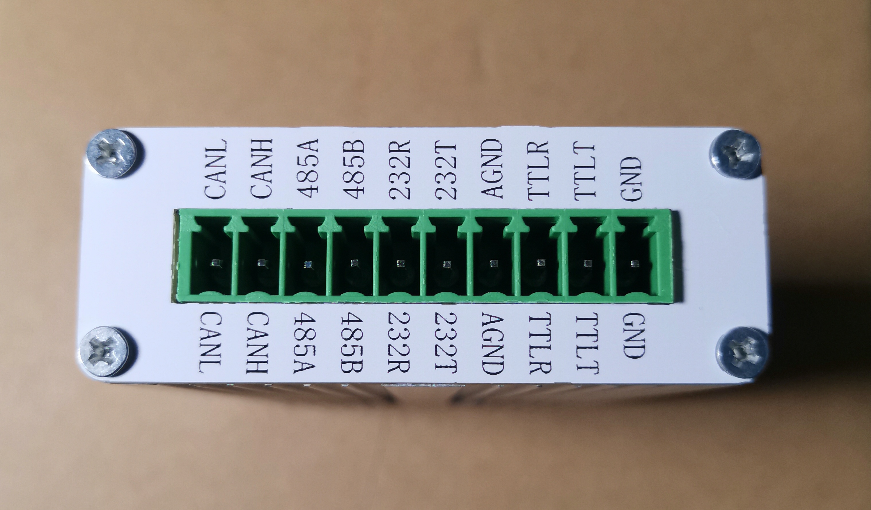
CANable and USB to TTL/RS232/RS485 combo
CANable and USB to TTL/RS232/RS485 combo
USB to CANable all-in-one USB to 485 module, USB to RS232 module, USB to TTL module.
Components can be soldered as needed: 1. USB converter TTL/RS232/RS485 non-isolated; 2. USB converter TTL/RS232/RS485 isolated; 3. USB converter TTL/RS232/RS485 & CANable, 2-in-1 non-isolated; 4. USB converter TTL/RS232/RS485 & CANable, 2-in-1 isolated.


Attached is the CANable firmware flashing
shell link: https://m.tb.cn/h.gW8qysKmCcEtYsf?tk=XPZYWEj8Txt
CANable_MKS_fw.zip
PDF_CANable and USB to TTL-RS232-RS485 2-in-1.zip
Altium_CANable and USB to TTL_RS232_RS485 combo zip
PADS_CANable and USB to TTL_RS232_RS485 combined package.zip
BOM_CANable and USB to TTL_RS232_RS485 combined.xlsx
92560
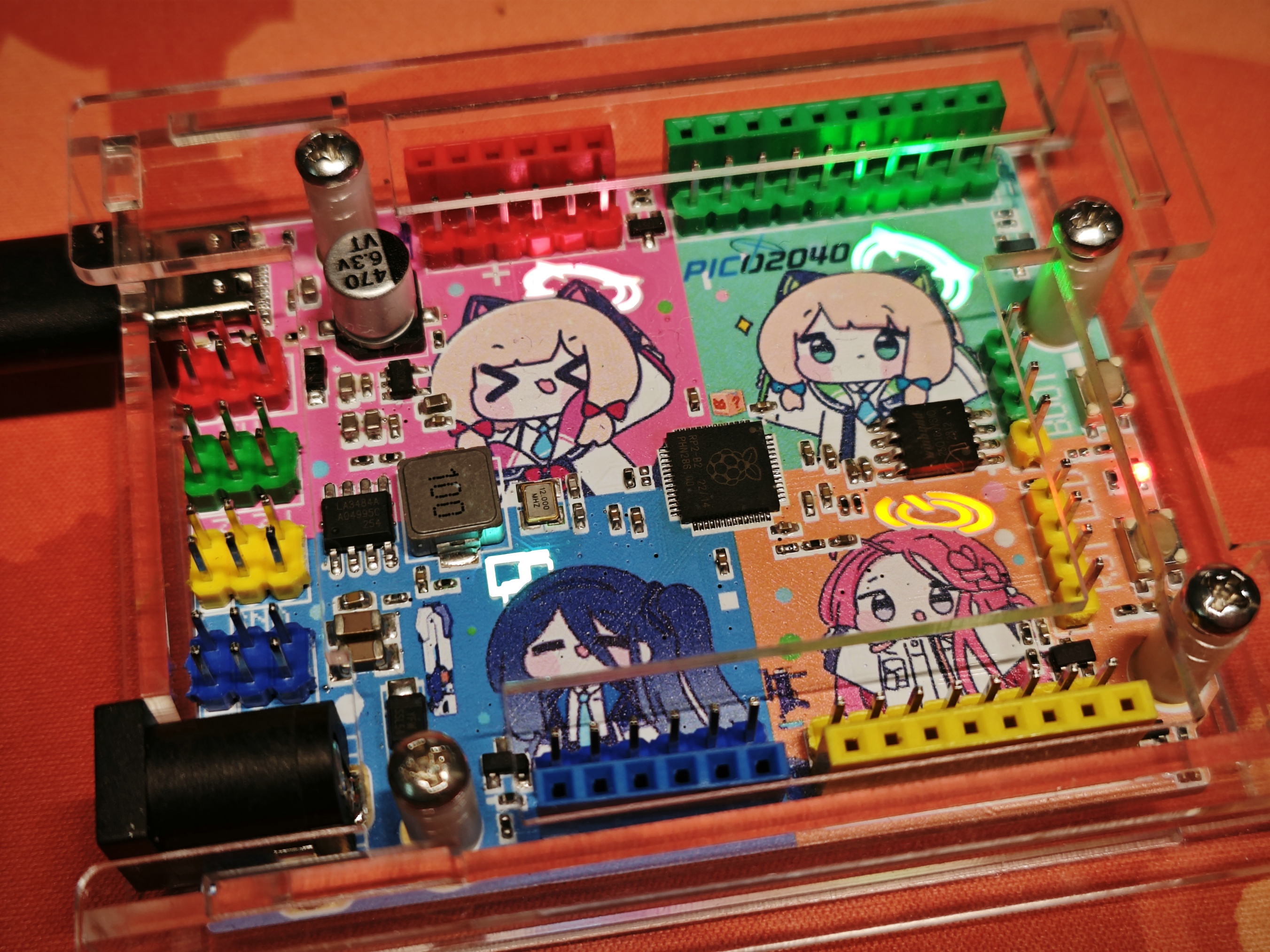
[Blue Archives] Raspberry Pi RP2040 Color Screen Printed Development Board
You're right, but *Azure Archives* is a mobile game developed by NEXON of South Korea and distributed by Yostar Interactive Entertainment Co., Ltd. of China. It was launched simultaneously on all platforms on November 9, 2021. The simplified Chinese version of the game was published by Ningbo East Coast Electronic Audio-Visual Publishing Co., Ltd., and distributed by Shanghai Xingxiao Network…
Considering the copyright issues associated with color silkscreen printing, and the potential for resale and commercial use, I will no longer provide complete designs. I will only provide copyright-free backgrounds or complete designs with full watermarks. If you need color silkscreen printing, you'll need to find the images yourself, assemble them, and then place them on the PCB. Alternatively, you can obtain authorization from the relevant copyright holders or companies, submit screenshots of the authorization, and I can provide the original source files.
Wow!
You're right, but *Azure Archives* is a mobile game developed by NEXON (Korea) and distributed by Yostar Interactive Entertainment Co., Ltd. in China. It was launched simultaneously on all platforms on November 9, 2021. The simplified Chinese version of the game is published by Ningbo East Coast Electronic Audio-Visual Publishing Co., Ltd., and operated by Shanghai Xingxiao Network Technology Co., Ltd. In the game, players will play the role of a teacher, leading students with diverse personalities through numerous trials, defeating enemies, and searching for the truth.
You're right, but *Let's Create! Electronic Designers' Assault* is a brand-new open-world sandbox game independently developed by JLCIC. The game takes place in a fantasy world called the "Workspace," where those chosen by the bear are granted the role of "Engineering Creator," guiding the arrangement and combination of components. You will play a mysterious character called "Engineering Member," encountering components with different packages and special requirements in the free wiring process. Together with them, you will defeat flying wire clues, find the lost "DRC Errors: 0"—and gradually uncover the truth of "OSHWHub."
Bilibili video: https://www.bilibili.com/video/BV1UF4m177QS/

1. Introduction: This
is a color silkscreen development
board It features a built-in halo light for four small characters from the game development department.
2. Schematic Diagram
: The schematic shows the most basic system.
GPIOs 0, 10, 16, and 25 are led out to the halo lights.

The LEDs on the back are reversed and surface-mounted . The colors are
pink, emerald green, blue-white, and orange.

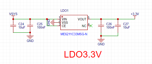
The DC-DC converter uses the domestic Jingyi LA3484, and the

LDO is the domestic Weimeng 6211.
3. Color Silkscreen
: JLC color silkscreen technology is used on both sides .


The original color silkscreen
files are available in the PSD file. Images are from Pixiv artists:
The following materials were used

: Top layer:
PID: 107030530 Artist: chamshheeooll
PID: 107064425 Artist: chamshheeooll
PID: 108664591 Artist: chamshheeooll
PID: 109625056 Artist: chamshheeooll
PID: 111148581 Artist: 아니아나 (Aniana)
Base layer:
PID: 114740261 Artist: Black dog
Please abide by the open source license and do not use it for commercial purposes!
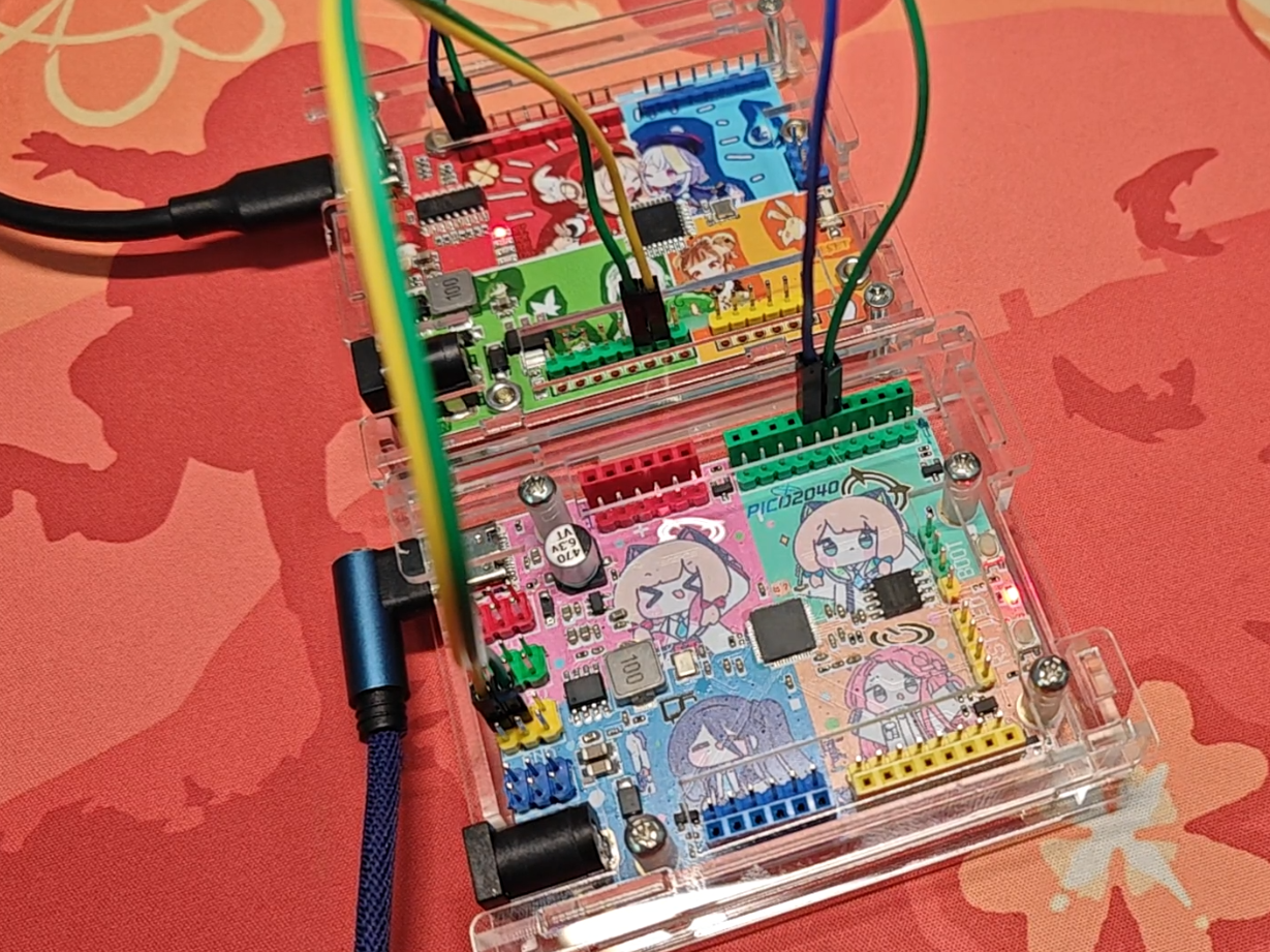
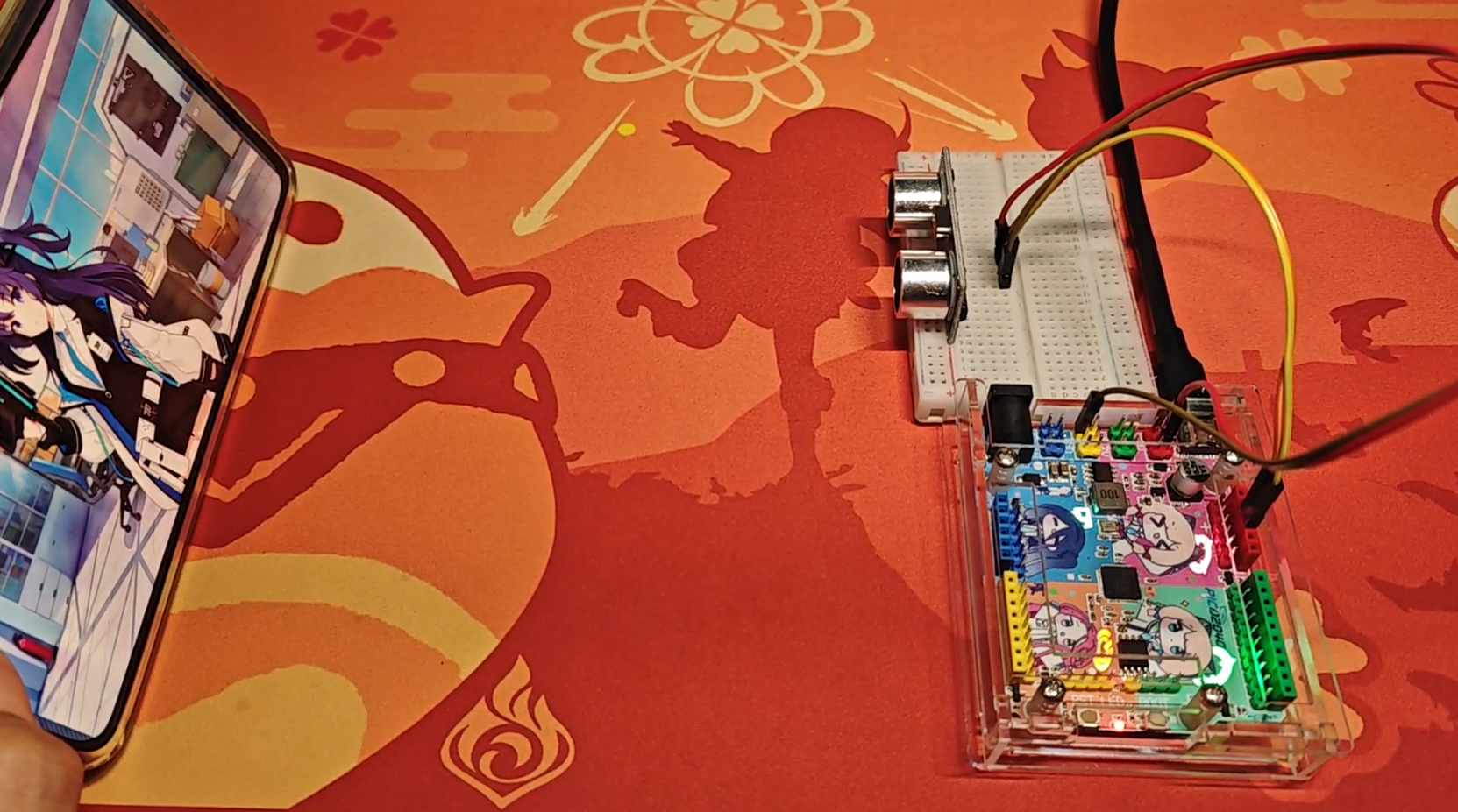
4. Usage Example
4.1 IIC Communication
Programming Host Slave


IIC receives the sent information and lights up the corresponding light
4.2 Email Mom's Defense War


Uses ultrasonic SR04 for distance measurement, light off when the distance is small, light on when the distance is large

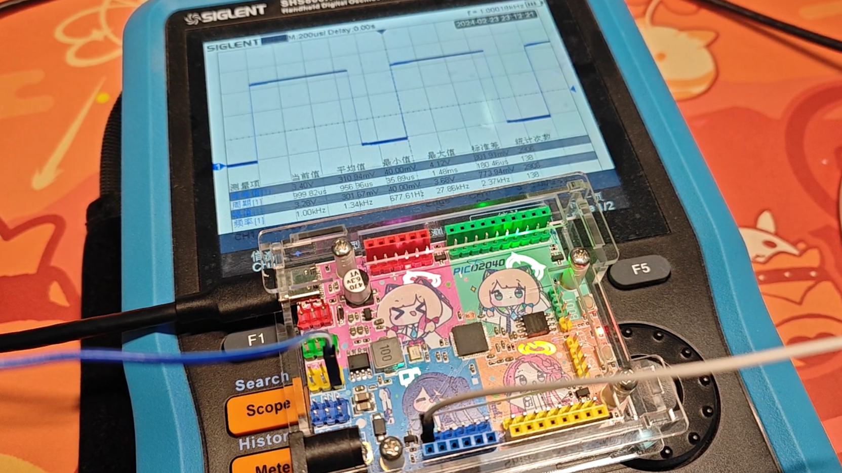
4.3 PWM
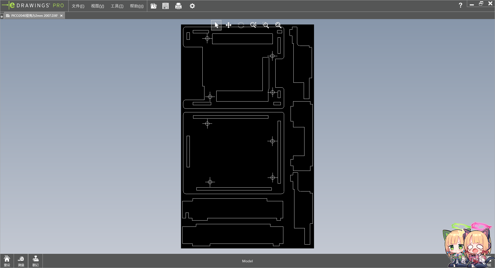
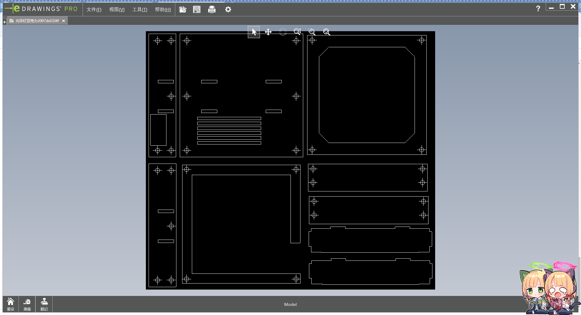
5. Acrylic Shell
Uses SW to draw
2mm thick acrylic
See the attached structure. 7z


has a file that can be ordered directly: PICO2040 Acrylic 2mm 2007.DXF
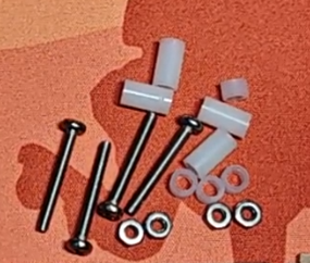
Assembly parts are as follows:
Name
Quantity
3.2*5*9 Plastic spacers
4
3.2*5*3 Plastic spacers
4
M2.5*20 Screws
4
M2.5 Nuts
4
Example.7z
Structure.7z
Acrylic front flash installed.mp4
Acrylic backlight installed.mp4
PICO2040 TOP .psd
PICO2040 BOTTOM.psd
PDF_【Azure Archives】Raspberry Pi RP2040 Color Silkscreen Development Board.zip
Altium_【Azure Archives】Raspberry Pi RP2040 Color Silkscreen Development Board.zip
PADS_【Azure Archives】Raspberry Pi RP2040 Color Silkscreen Development Board.zip
BOM_【Azure Archives】Raspberry Pi RP2040 Color Silkscreen Development Board.xlsx
92562
【Azure Archives】Caiyu Green Halo Night Light
Very delicious
Considering the copyright issues associated with color silkscreen printing, and the potential for resale and commercial use, I will no longer provide complete designs. I will only provide copyright-free background boards or complete designs with full watermarks. If you require color silkscreen printing, you will need to find the images yourself, assemble them, and then place them on the PCB. Alternatively, you can obtain authorization from the respective copyright holders or companies and submit screenshots of the authorization to me. I can provide the original source files.
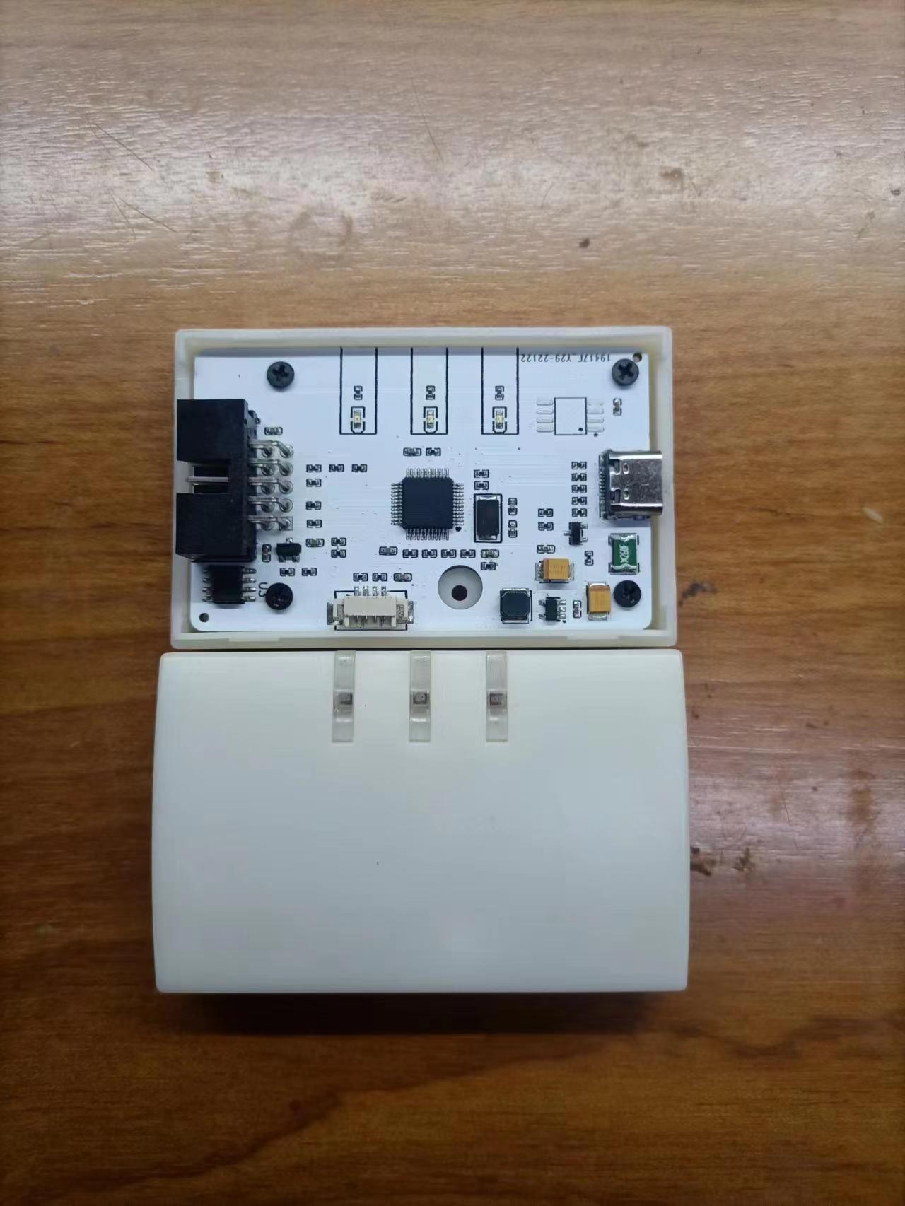
1. Introduction:
A night light using TTP223 for touch control, DY-SV17F for voice output, and ASRPRO for voice recognition is
also available from Xiaotao. A detailed tutorial can be found here: https://oshwhub.com/aknice/wei-lan-dang-an-cai-yu-tao-jing-guang-huan-xiao-ye-deng
The rear toggle switch allows you to choose between constant light or a light that illuminates for a period after touch/voice activation before turning off.

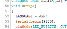
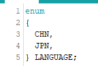
Code initialization allows you to select the playback language; the default is Japanese.
2. Material Purchase:
RGB diffused light board
: https://item.taobao.com/item.htm?_u=4qavhl8ad02&id=591506 453636&spm=a1z09.2.0.0.67002e8dE25jFb
Voice playback module
https://item.taobao.com/item.htm?_u=4qavhl8bedd&id=633220495389&spm=a1z09.2.0.0.67002e8dE25jFb
Voice recognition module + microphone + speaker
Voice recognition is not essential, optional. Speaker can be purchased with the same specifications
https://item.taobao.com/item.htm?spm=a1z09.2.0.0.67002e8dE25jFb&id=684816007765&_u=4qavhl8724f
3. Bilibili video
https://www.bilibili.com/video/BV1pe411i7Hj/
Xiao Lv Voice Control.hd
Green Voice.zip
Blink.7z
.7z casing
PDF_【Azure Archives】Caiyu Green Halo Night Light.zip
Altium_【Azure Archives】Talented Feather Green Halo Night Light.zip
PADS_【Azure Archives】Talented Feather Green Halo Night Light.zip
BOM_【Azure Archives】Caiyu Green Halo Night Light.xlsx
92563
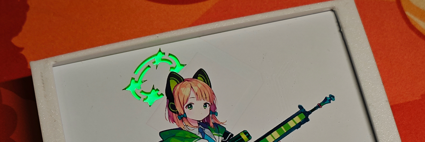
[Azure Archives] Saiwa Momoi Halo Night Light
Very delicious
Considering the copyright issues associated with color silkscreen printing, and the potential for resale and commercial use, I will no longer provide complete designs. I will only provide copyright-free background boards or complete designs with full watermarks. If you require color silkscreen printing, you will need to find the images yourself, assemble them, and then place them on the PCB. Alternatively, you can obtain authorization from the respective copyright holders or companies and submit screenshots of the authorization to me. I can provide the original source files.
1. Introduction:
The night light using TTP223 for touch, DY-SV17F for voice output, and ASRPRO for voice recognition
is basically the same as the green one, only the layout has been changed: https://oshwhub.com/aknice/azure-archives-only-feather-green
The back switch allows you to choose between constant light or a light that illuminates for a period after touch/voice activation before turning off.

Code initialization allows you to select the playback language; the default is Japanese.

2. Material Purchase:
RGB diffused light board
https://item.taobao.com/item.htm?_u=4qavhl8ad02&id=591506453636&spm =a1z09.2.0.0.67002e8dE25jFb
Voice playback module
https://item.taobao.com/item.htm?_u=4qavhl8bedd&id=633220495389&spm=a1z09.2.0.0.67002e8dE25jFb
Voice recognition module + microphone + speaker
Voice recognition is not essential, optional. Speaker can be purchased with the same specifications
https://item.taobao.com/item.htm?spm=a1z09.2.0.0.67002e8dE25jFb&id=684816007765&_u=4qavhl8724f
3. Code burning
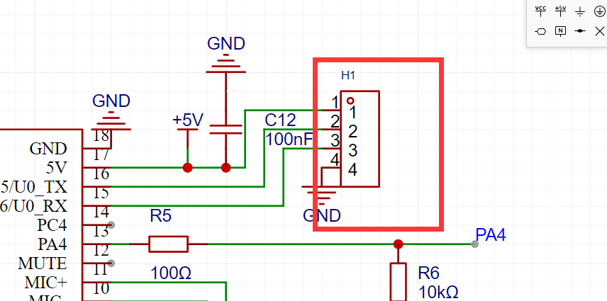
for the ESP8266 main controller: For the reserved serial port burning header,
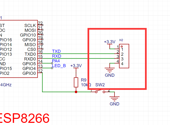
disconnect the serial port resistor connecting to the voice playback module before burning; otherwise, serial port interference will prevent input.

4. Offline voice burning
uses the Tianwen voice module. See the Tianwen voice module tutorial for details.

Install Tianwen Block, register an account,
open the Tao offline voice
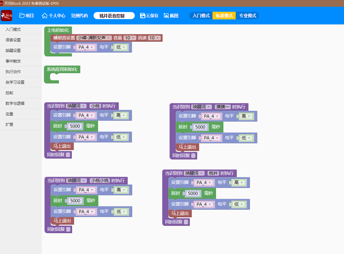
serial port, connect to the Tianwen serial port,
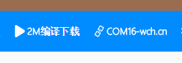
and click download.
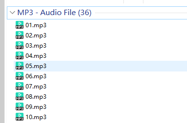
5. Voice package burning:
Connect the DY-SV17F voice output module using a microUSB. A 4MB USB drive will appear on the computer. Place all MP3 files on it.
OGG files are not recognized; use pre-transcoded MP3s instead.
6.
Directly print acrylic

with modeling files

: Acrylic six-sided nuts (10 per machine, 10x10 cm). Purchase:
https://item.taobao.com/item.htm?_u=qqavhl8f634&id=741904654013&spm=a1z09.2.0.0.67002e8dYgv4io
7. Bilibili video:
https://www.bilibili.com/video/BV1vN4y1J7Fy/
Momoi Voice Control.hd
Momoi Voice.7z
Blink.7z
Casing (New).7z
PDF_【Azure Archives】Saiyu Momoi Halo Night Light.zip
Altium_【Azure Archives】Taeba Momoi Halo Night Light.zip
PADS_【Azure Archives】Saiyu Momoi Halo Night Light.zip
BOM_【Azure Archives】Taeyu Momoi Halo Night Light.xlsx
92564
STM32F103C8T6 Multifunctional Development Board
A development board with a built-in programmer, supporting fully automatic downloading, compatible with both 5V and 3.3V microcontrollers.
Since conventional STM32 development boards require the purchase of a separate programmer, which can lead to jumper contact problems over time, and programmers are not inexpensive, this development board was designed. The main body of the board is the same as other development boards on the market, except for the addition of a programmer, greatly simplifying its use. Although the programmer uses the CH340 chip, it is completely different from those on the market. It not only features a TYPE-C interface, solving the problem of insufficient cable length in traditional programmers, making it very user-friendly for desktop users, but it also supports fully automatic downloading, compatible with both 5V and 3.3V microcontrollers, eliminating the need for manual reset; all reset functions are handled by hardware circuitry. It includes 5V and 3.3V overcurrent and short-circuit protection to prevent damage to the development board caused by reversed peripheral hardware connections or short circuits.
The pin definitions of this development board are exactly the same as the common C8T6 development board on the market; the only difference is the addition of a programmer board. This development board does not include pre-built code, but the code from Jiangxie Technology can be used. Please download the code from their official website if needed.
This section describes the software and hardware settings for fully automatic downloading
. Software settings: First, insert the development board into the computer, then click "Search Serial Ports" and select the CH340 serial port.

Hardware settings: Set boot0 to 1 and boot1 to 0. After downloading, you need to set boot0 to 0 and then press the reset button on the development board for the program to run normally.
Finally, if all settings are correct but automatic downloading occasionally fails, simply press the reset button on the downloader. (Note that the reset button on the downloader is only effective after clicking "Burning Code." Do not press the reset button on the downloader or development board when burning code normally, as this will cause the program download to fail.)
STM32F103C8T6 Multifunctional Development Board_v148_2024-08-15-16-20.zip
SCH_STM32F103C8T6103C8T6 Multifunctional Development Board_2024-08-30.pdf
PickAndPlace_STM32F103C8T6103C8T6 Multifunctional Development Board_2024-08-30.csv
Netlist_STM32F103C8T6103C8T6 Multifunctional Development Board_2024-08-30.tel
Gerber_STM32F103C8T6103C8T6 Multifunctional Development Board_2024-08-30.zip
BOM_STM32F103C8T6103C8T6 Multifunctional Development Board_STM32F103C8T6103C8T6 Multifunctional Development Board_2024-08-30.xlsx
PDF_STM32F103C8T6 Multifunctional Development Board.zip
Altium_STM32F103C8T6 Multifunctional Development Board.zip
PADS_STM32F103C8T6 Multifunctional Development Board.zip
BOM_STM32F103C8T6 Multifunctional Development Board.xlsx
92565
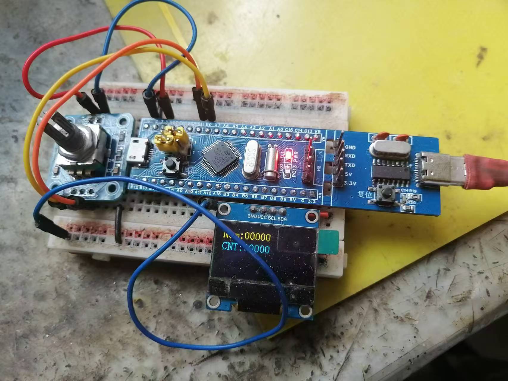
Based on CW32 voltage and current meter
A voltage and current meter was replicated based on the CW32 geospatial development board, realizing a simple voltage and current measurement function.
I. Project Introduction
Input DC 5-35V, power circuit incorporates 1N5819 with reverse connection protection. This project achieves the following functions: 1. Voltage measurement: 0-30V 2. Current measurement: 0-3A 3. Voltage calibration: 3V, 8V, 15V 4. Current calibration: 0.5A
, 1.5A II. Button and Mode Introduction
SW1: Switch Mode SW2: Calibration SW3: Return to
Mode 0 Function: General measurement. Left digital tube displays voltage value, right digital tube displays current value.
Mode 1 Function: 3V calibration. Left digital tube displays V.03, right digital tube displays voltage value.
Mode 2 Function: 8V calibration. Left digital tube displays V.08, right digital tube displays voltage value.
Mode 3 Function: 15V calibration. Left digital tube displays V.15, right digital tube displays voltage value.
Mode 4 Function: 0.5A calibration. Left digital tube displays A.0.5, right digital tube displays current value.
Mode 5 Function: 1.5A calibration. Left digital tube displays A.1.5.
When calibrating the current value displayed on the right digital tube, do not solder R0.
When calibrating the voltage, use a jumper cap connected to H5. Use a multimeter in voltage mode, connect the red probe to T_V and the black probe to TGND. Adjust RP1 and press the calibration button. For example, to calibrate 3V, connect the multimeter, power on the board, and adjust RP1 until the multimeter displays 3V. Press the calibration button. Repeat this process for subsequent
calibrations. When calibrating the current, use a jumper cap connected to H6. Use a multimeter in voltage mode, connect the red probe to TI+. Connect the black probe to TGND and adjust RP2 so that the multimeter reading multiplied by 10 equals the current to be calibrated, for example, to calibrate 0.5A. Connect the multimeter, power on the board, and adjust RP2 until the multimeter displays 0.05V. Press the calibration button and repeat the process. When
measuring voltage, connect the jumper cap to H5 and H3 sockets. The left side is negative and the right side is positive. Connect the jumper cap to the object being measured, and the voltage value will be displayed on the left digital display.
When measuring voltage, connect the jumper cap to H6 and CH1 sockets. The left side is negative and the right side is positive. Connect the jumper cap to the object being measured, and the current value will be displayed on the right digital display.
III. Firmware Burning
1. Firmware: Project.hex in the attachment
2. If using Keil to burn the .hex file:
Step 1: Create a CW32 project
Step 2: Click the magic wand and find output
Step 3: In output, click Select Folder for Objects... on the left and set the path to the downloaded .hex file
in the attachment Step 4: In output, click Name of Enter the full name of the downloaded .hex file in the Executable box (remember to include the filename extension).
Step five is the normal burning process.
A demonstration video is available in the attachment.
Project.hex
Voltage demonstration.mp4
PDF_Based on CW32 Voltage and Current Meter.zip
Altium_Based on CW32 Voltage and Current Meter.zip
PADS_Based on CW32 Voltage and Current Meter.zip
BOM_Based on CW32 Voltage and Current Meter.xlsx
92566
electronic


 京公网安备 11010802033920号

 3SMAJ5927B


