
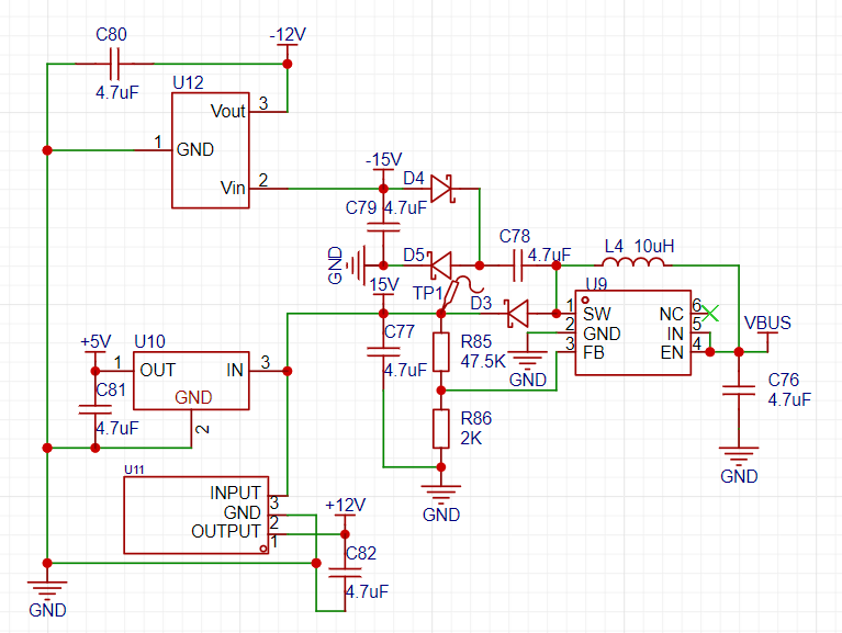
 positive and negative power supplies for the op-amp section are provided by this part.
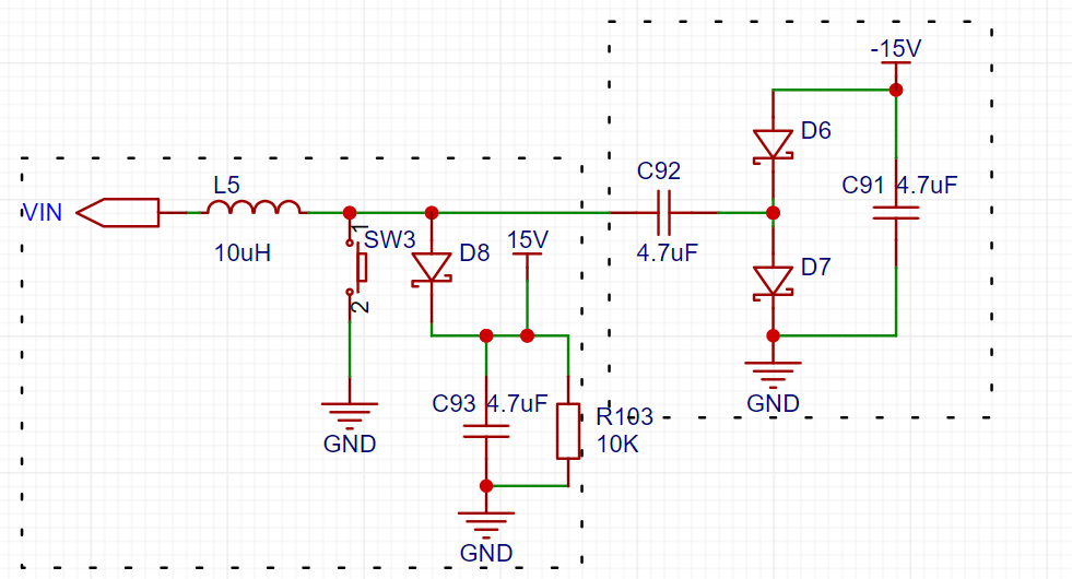 left box is a simplified BOOST section, which will not be analyzed here. Let's look at the circuit in the right box. Because the high-speed switching of the switch on the left side turns the power supply on the left side of C92 into a pulse signal. When the signal goes from low to high, the capacitor C92 charges (left +, right -). When the signal goes from high to low, the left side of C92 becomes 0 volts, but the voltage difference across the capacitor cannot change abruptly, causing the voltage on its right side to become -V. This allows the current to flow through GND->C91->D6->C92->GND. The final result is that the voltage at the positive terminal of D6 is a negative voltage slightly higher than -V.
 This is the 3.3V power supply of my system, which includes both the switching power supply and the LDO. In actual soldering, I only soldered the switching power supply.
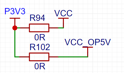 In my initial version, I only made a jumper to 3.3V for the signal relay power supply, but the signal relay I bought was a 5V power supply specification, which was a careless oversight. Therefore, two power supply options were added here.
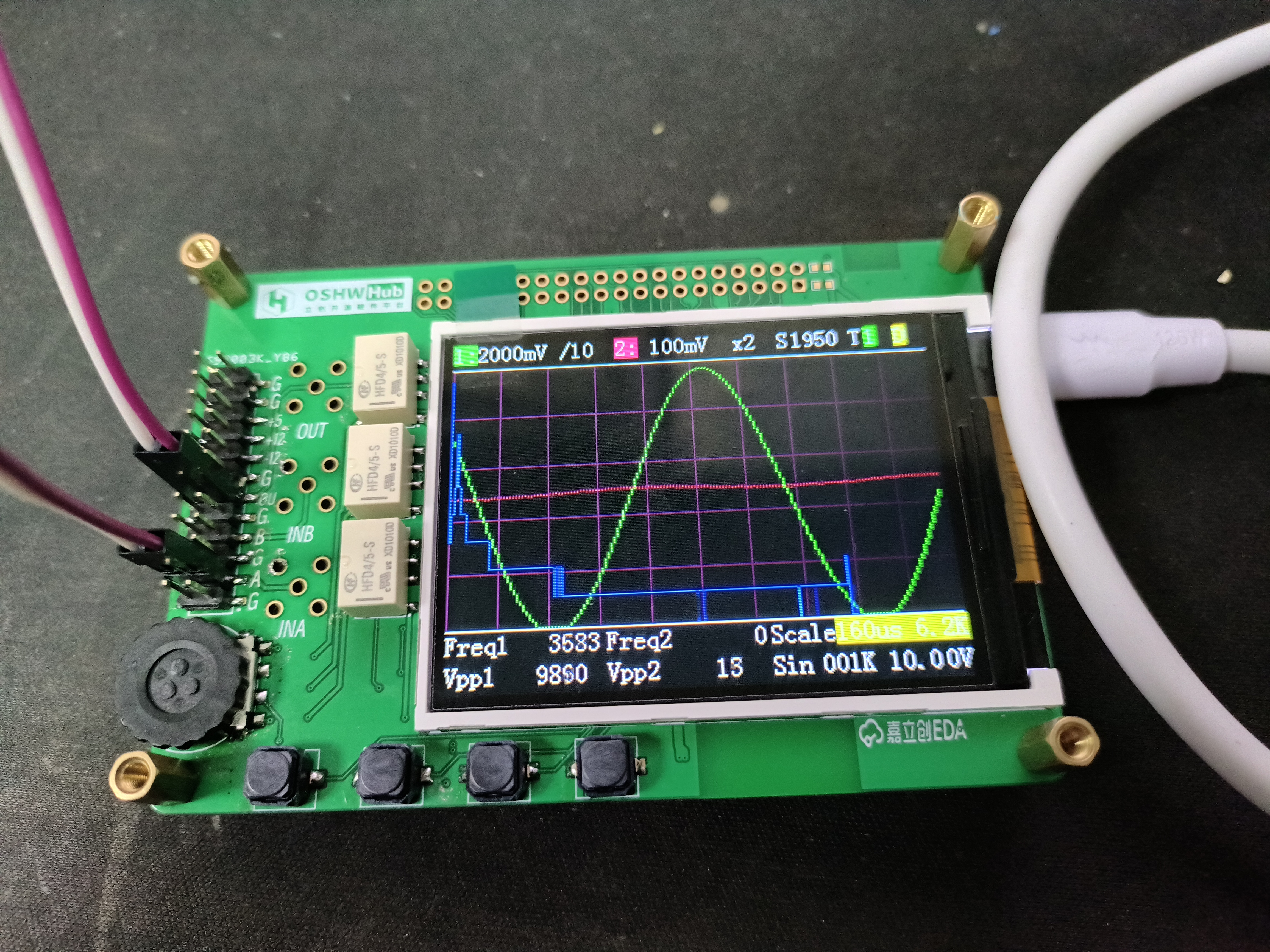
 The official documentation for the oscilloscope's analog front-end clearly explains attenuation, gain, DC bias, and comparator triggering.
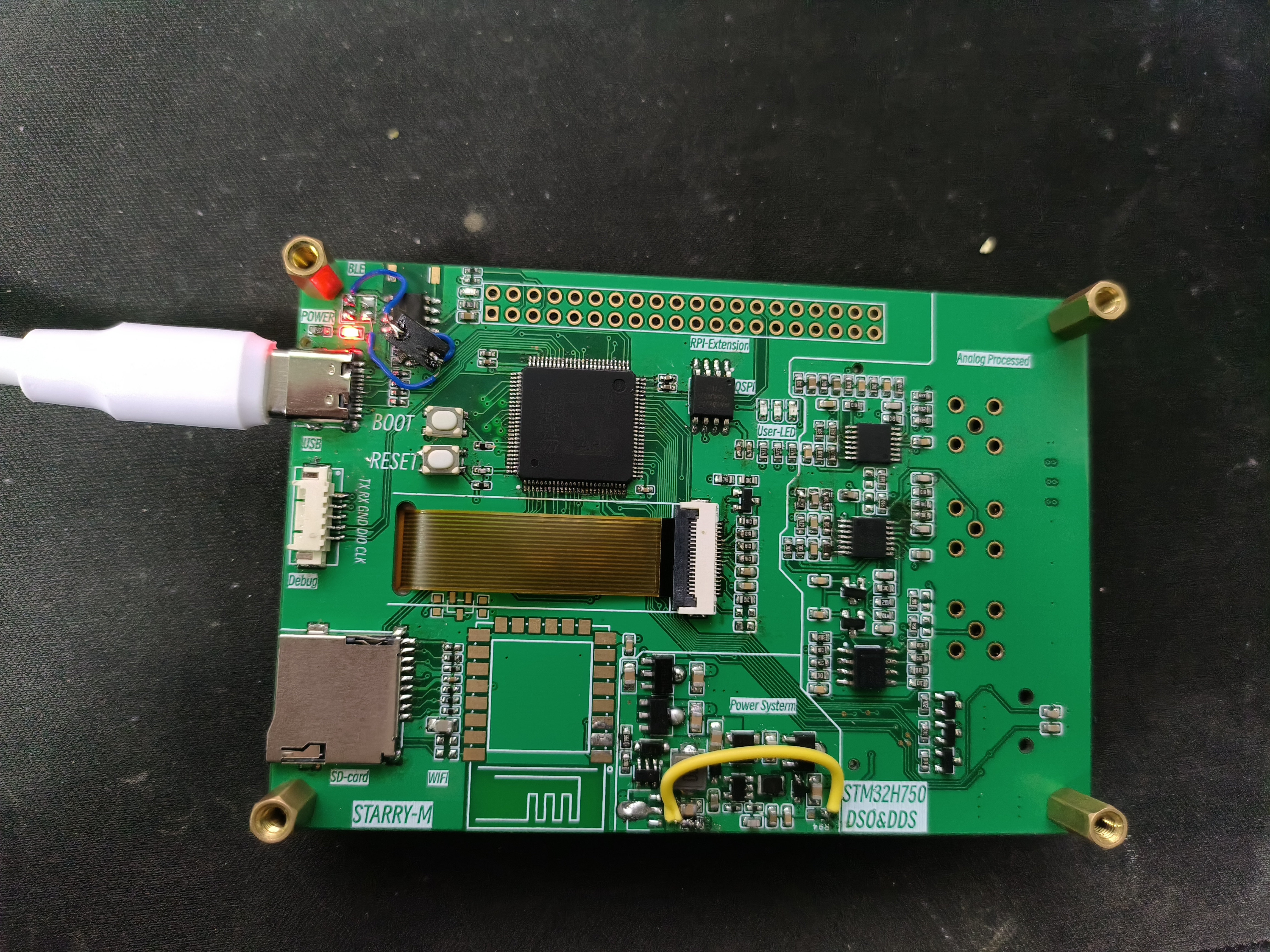
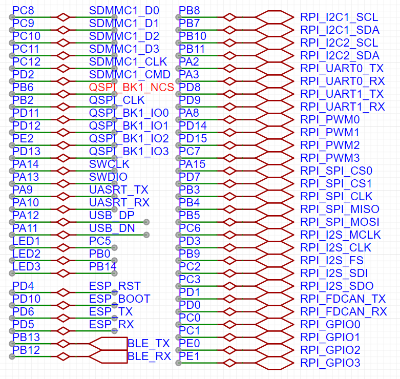 I added some peripherals to the board, such as a TF card for expanding waveform capture functionality; QSPI for external FLASH; and KT6368A Bluetooth and ESP8266WIFI for remote control and display. For the remaining pins, I chose the Raspberry Pi expansion interface, which has the most compatible modules, allowing for easy direct connection of various modules. To simplify layout and routing, I modified some interface pins


All reference designs on this site are sourced from major semiconductor manufacturers or collected online for learning and research. The copyright belongs to the semiconductor manufacturer or the original author. If you believe that the reference design of this site infringes upon your relevant rights and interests, please send us a rights notice. As a neutral platform service provider, we will take measures to delete the relevant content in accordance with relevant laws after receiving the relevant notice from the rights holder. Please send relevant notifications to email: bbs_service@eeworld.com.cn.
It is your responsibility to test the circuit yourself and determine its suitability for you. EEWorld will not be liable for direct, indirect, special, incidental, consequential or punitive damages arising from any cause or anything connected to any reference design used.
Supported by EEWorld Datasheet
EEWorld
subscription
account

EEWorld
service
account

Automotive
development
community

Robot
development
community

About Us Customer Service Contact Information Datasheet Sitemap LatestNews


Room 1530, 15th Floor, Building B,
No.18 Zhongguancun Street,
Haidian District,
Beijing, Postal Code: 100190
China
Telephone: 008610 8235 0740
 京公网安备 11010802033920号

 CL100A


