Design Purpose:
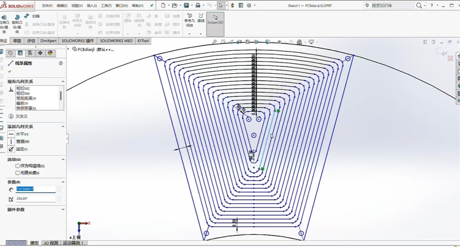
To adapt to certain special application scenarios, such as those requiring extremely small size and thickness, a brushless motor with axial flux is a good choice. Therefore, I designed this PCB motor, with an overall thickness of less than 1cm, using a 12N16P design. Testing showed it can start and run normally even without sensors, with low operating noise. It is made using a 6-layer board, allowing for direct prototyping.
PCB Design:
Drawing the PCB motor coils on EDA software is difficult. It was first drawn using CAD software, then exported as a DXF file to JLCPCB EDA for coil design.

Structural Design:
The magnets used here are rectangular, arranged in an NSNSNSNSNS... pattern.

Operational
Testing: It requires only 18V to start normally and is ready for use.

PCB motor.mp4
PDF_PCB Motor-12N16P.zip
Altium_PCB Motor-12N16P.zip
PADS_PCB Motor-12N16P.zip
92601
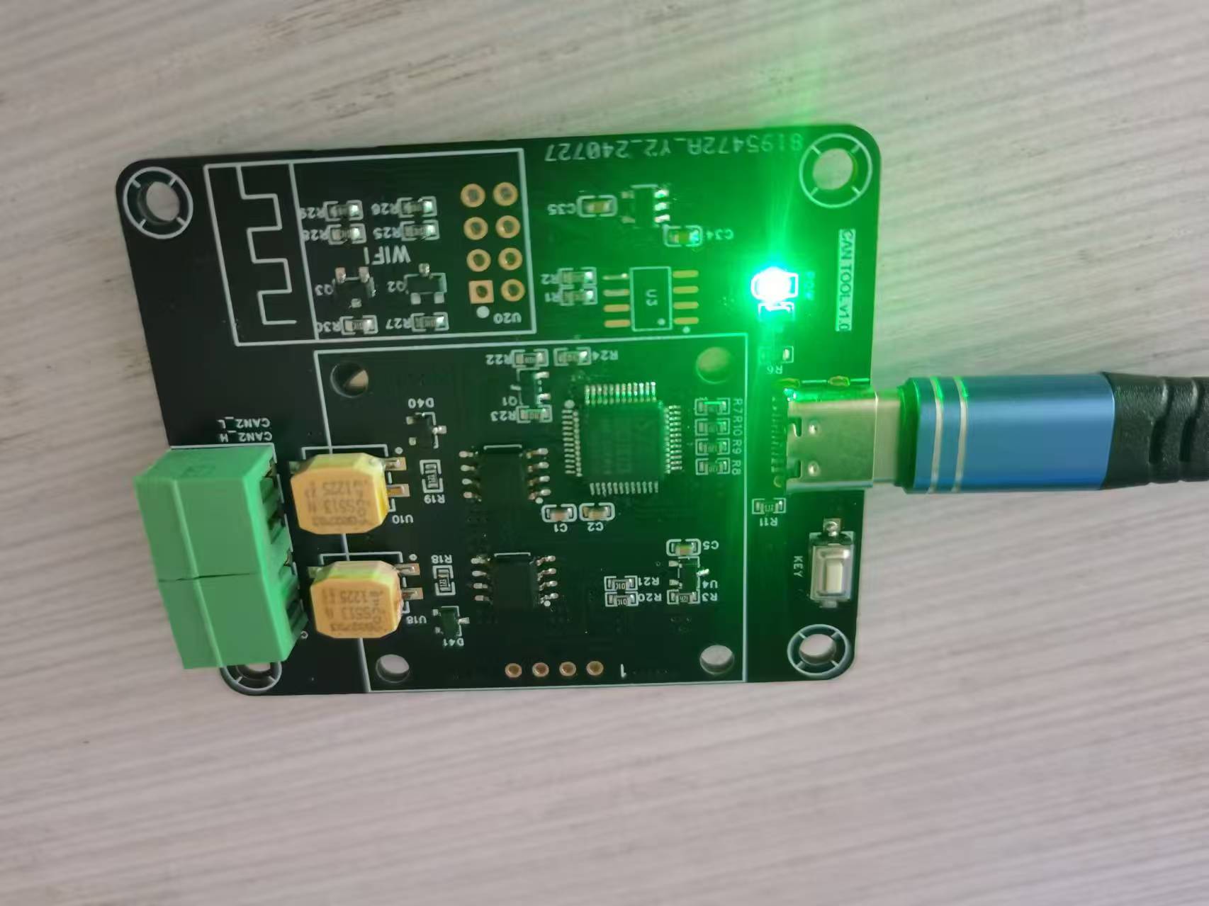
STC32 USB-CAN Communication Module
USB to CAN converter
Project Description
Main Functions:
1. USB-CAN communication module
2. Message display with OLED
3. WIFI module, can connect to host computer via WIFI
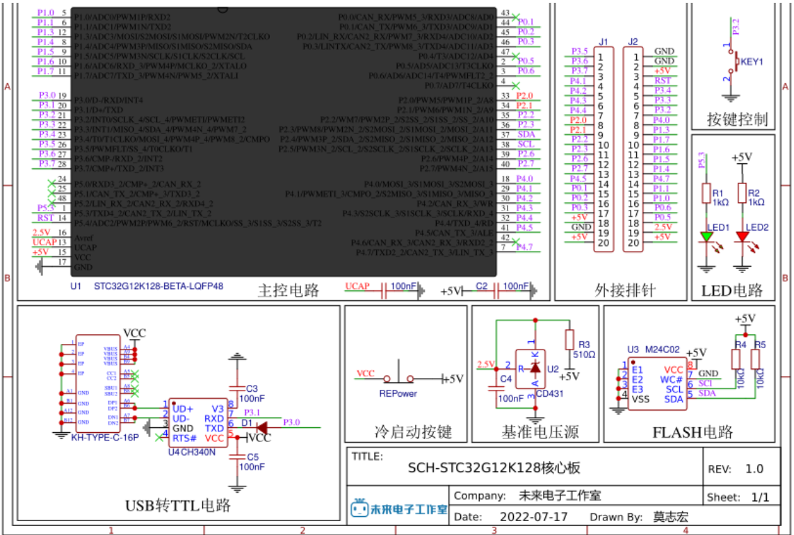
Schematic:
Core peripheral circuit Future Studio's reference minimum system, no serial port version
https://oshwhub.com/wei-lai-dian-zi-gong-zuo-shi/zui-xiao-xi-tong-stc32g12k128-hid-xia-zai
WIFI interface, ESP01S

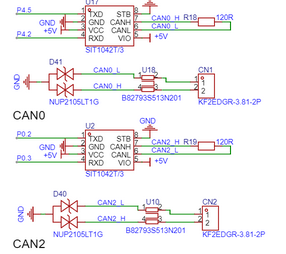
uses two CAN channels, the chip is the domestic SIT1042T.
Verification effect, power supply test OK, using STC-ISP software, operation is consistent with the manual, but it is not recognized, and the STC USB Writer is not displayed. The board was resoldered once, but it is still the same. However, I am using the same chip. I suspect that the chip may be broken. I have been struggling with it for a long time, so I gave up on
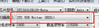
the physical pictures.
PDF_STC32 USB-CAN Communication Module.zip
Altium_STC32 USB-CAN communication module.zip
PADS_STC32 USB-CAN communication module.zip
BOM_STC32 USB-CAN Communication Module.xlsx
92603
The STM32F103 flight controller uses Naza firmware.
Based on the STM32F103 flight controller, the pins are designed according to the Naza firmware.
Reserved PWM (unverified)
onboard brushed driver (verified and test-flown)
with 1s power supply.
d0fbc65634c04c299ae3df69699b200f.mp4
betaflight_3.2.5_NAZE.hex
PDF_stm32f103 flight controller using Naza firmware.zip
Altium_stm32f103 flight controller uses Naza firmware.zip
PADS_stm32f103 flight controller uses Naza firmware.zip
BOM_stm32f103 flight controller uses Naza firmware.xlsx
92604
Minimum system and procedures for controlling servo motors
It can control four servos, plus a P0 expansion port.
Project Functionality This design is based on the STC89C51/52 microcontroller and is a minimum system software code
for controlling a servo motor. #include "reg52.h" #include "intrins.h" #include "TMER0.H" sbit S1=P0^0; sbit S2 =P0^1; sbit SG_PWM1=P2^0; sbit SG_PWM2=P2^1; sbit SG_PWM3= P2^2; sbit SG_PWM4=P2^3; unsigned char count=0; unsigned char PWM1_count=0; unsigned char PWM2_count=0; unsigned char PWM3_count=0; unsigned char PWM4_count=0; void Delay1ms(unsigned int xms ) //@11.0592MHz { while(xms) { unsigned char data i, j; i = 15; j = 90; do { while (--j); } while (--i); xms--; } } void main() { Timer0_Init(); S1 = 1 ; PWM1_count=1; Delay1ms ( 100) ; Delay1ms(100); PWM1_count=3; Delay1ms (100) ; PWM2_count=3; Delay1ms (100); PWM3_count = 3 ; Delay1ms ( 100 ) ; PWM1_count=3; PWM4_count=3; } else { PWM1_count=1; PWM4_count=1; Delay1ms(100); PWM2_count=3; PWM3_count=3; } } } unsigned int T0Count; void Timer0_Routine() interrupt 1 { TL0 = 0x33; //??????? TH0 = 0xFE; //??????? count++; count%=40; if(count<PWM1_count) { SG_PWM1=1; } else { SG_PWM1=0; } if(count<PWM2_count) { SG_PWM2=1; } else { SG_PWM2=0; } if(count<PWM3_count) { SG_PWM3=1; } else { SG_PWM3=0; } if(count<PWM4_count) {
SG_PWM4=1;
}
else
{
SG_PWM4=0;
}
}
Note:
For cold start downloading of the microcontroller, when using the P0 serial port, you need to solder pull-up resistors yourself. Also,
please note
that the Comtasia company logo is from the Cyberpunk 2077 game; any resemblance is purely coincidental.
Servo control program.txt
PDF_Minimum System and Programs for Controlling Servo Motors.zip
Altium_Minimum System and Programs for Controlling Servo Motors.zip
PADS_Minimum System and Programs for Controlling Servo Motors.zip
92605
electronic


 京公网安备 11010802033920号

 DS1868E-10


