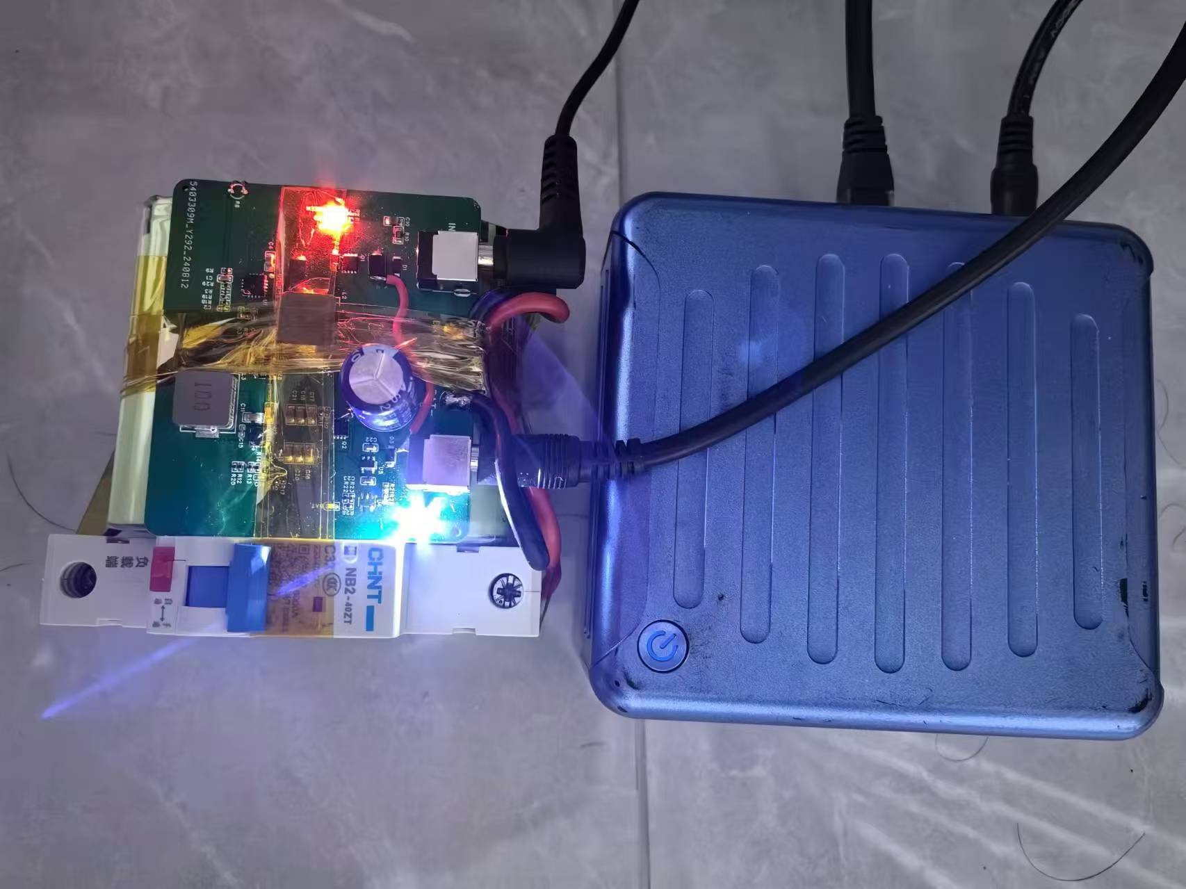
The input uses the original 19V adapter from the computer, and the output terminals use standard 5525DC terminals.
The MP26123DR-LF-Z chip charges three 12.6V lithium batteries in series. The chip has built-in over-temperature and overheat protection. The chip can be configured to charge two (8.4V) or three (12.6V) batteries. This project uses three batteries in series, so R3 does not need to be soldered.
A Panasonic 28650 lithium battery pack with three series and two parallel configurations is used. The finished product includes a protection board and an equalization board. You can choose a suitable capacity lithium battery pack according to your needs. Handle lithium batteries with caution; illegal modification of lithium battery packs is strictly prohibited.
The battery voltage is boosted to approximately 18.5V using a TPS61178RNWR as a backup power source. The output voltage is adjustable. Please refer to the chip datasheet to calculate the feedback resistor. Theoretically, the chip can output 10A, but this project only verified the hardware was working correctly at 3A. For higher current requirements, please recalculate the inductance value and thicken the corresponding traces to meet the high current requirements.
The power path management is manually implemented. When the adapter's 19V is available, the power supply charges the battery and supplies power to the output terminals through a D5-SS54 Schottky diode. At an output current of 1A, the Schottky diode's voltage drop is approximately 0.7V. At this time, the 18.5V supplied by the battery through the boost chip is controlled by PMOS-Q2 to remain non-conductive, and the load current is entirely provided by the power adapter.
When the adapter's 19V is disconnected, Q2 automatically conducts, and the 18.5V supplies power to the load through Q2.
Chip temperature: At a charging current of 2A, the MP26123DR-LF-Z chip surface temperature is approximately 60 degrees Celsius.
When powered by the battery, at a discharging current of 2A, the TPS61178RNWR surface temperature is approximately 80 degrees Celsius. For chips with higher currents, additional heat dissipation measures should be taken.
After 72 hours of high-temperature aging, all components operate stably.
The solution has been verified; please feel free to replicate it.
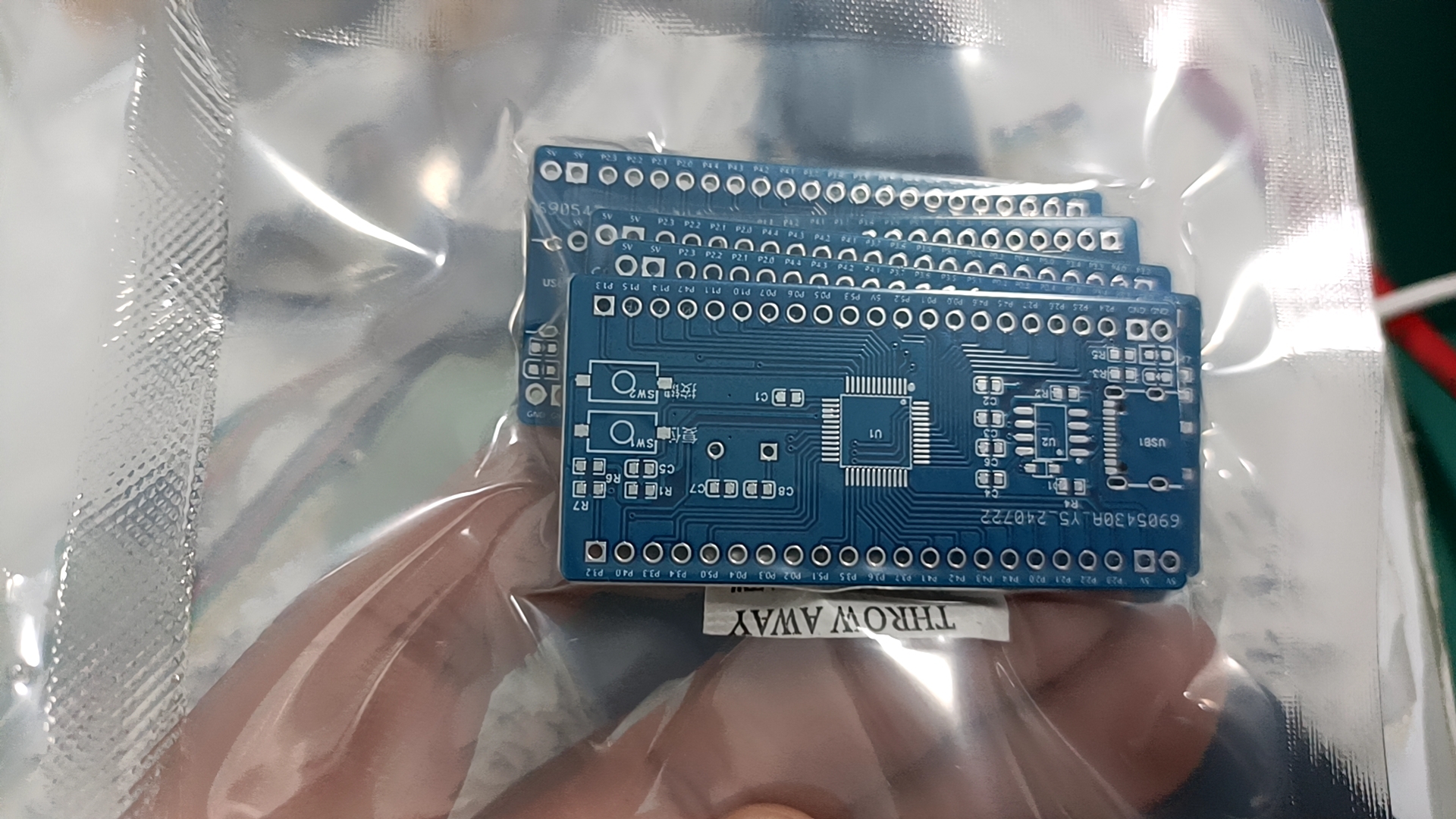
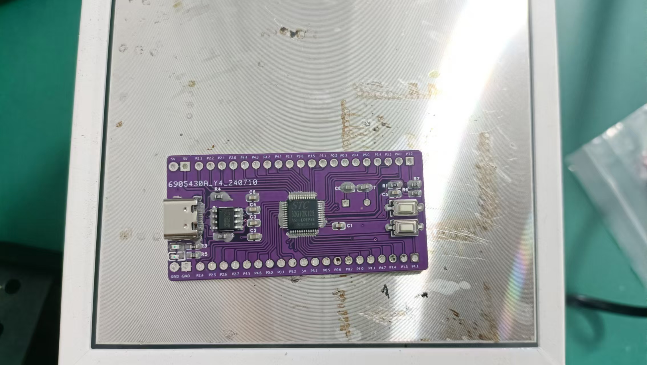
The STC32G12K128 small development board I designed is based on a high-performance 32-bit ARM Cortex-M3 core microcontroller launched by STC (Semiconductor Technology Corporation).
The STC32G12K128 series microcontrollers are 32-bit 8051 microcontrollers with a wide operating voltage range, launched by STC in 2022. The operating voltage of this series of microcontrollers is 1.9V~5.5V. Compared with the STC8H3K64S4 series microcontrollers, the STC32G12K128 series microcontrollers have added peripherals such as DMA, RTC, and CAN.
This small development board based on the STC32G12K128 has the following features:
1. All I/O pins are brought out via headers
. 2. Three separate 5V and three GND header interfaces are added.
3. Powered by a USB interface at 5V.
4. Downloads via USB interface, simple and easy to use.
5. Built-in power indicator; includes a programmable LED indicator.
6. Built-in 32768Hz crystal for easy debugging of the internal RTC.
(Third board test attempt
, second board test attempt failed
! [WeChat image_20240726085525.jpg]
First board test attempt failed
! [WeChat image_20240726085530.jpg]
![WeChat image_20240726085533.jpg])

PDF_STC32G12K128 Mini Development Board.zip
Altium_STC32G12K128 small development board.zip
PADS_STC32G12K128 small development board.zip
BOM_STC32G12K128 Mini Development Board.xlsx
92627
CW32-Voltage and Current Meter
Voltage and current meters based on LCSC development board-CW32F030
Video Link:
Bilibili Video -- Function Demonstration and Introduction
Description
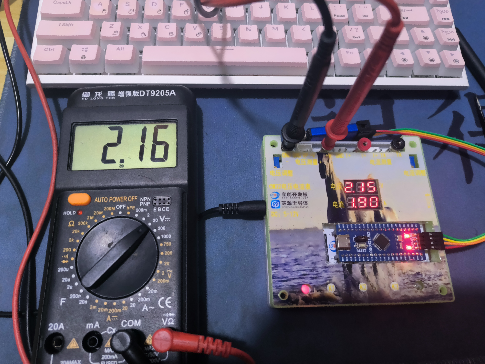
This project is a voltage and current meter based on CW32F030, with voltage and current measurement functions.
Approximate voltage measurement range: 0-30V (can be simulated for testing)
Approximate current measurement range: 0-3A (can be simulated for testing)
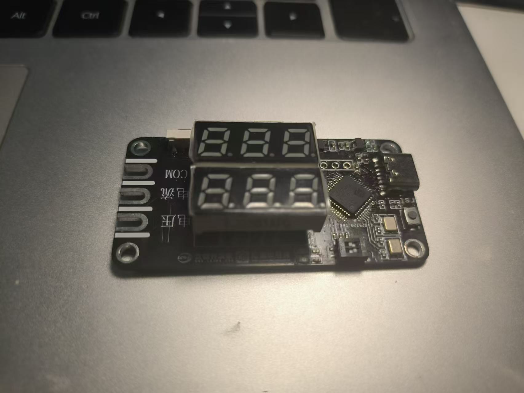
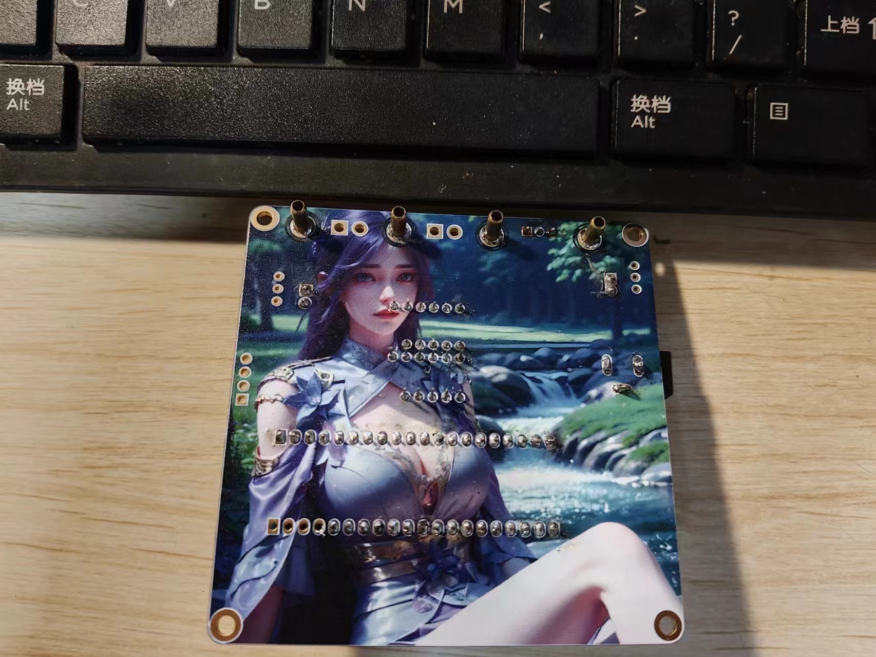
Photos of the finished product are shown below. This was
my first time using 3D printing and panel printing, and there were some minor mishaps, but thankfully it didn't affect the overall result much.
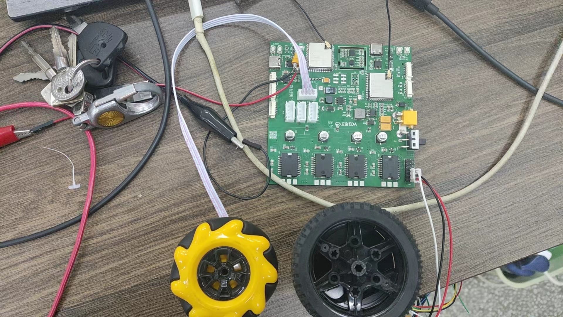
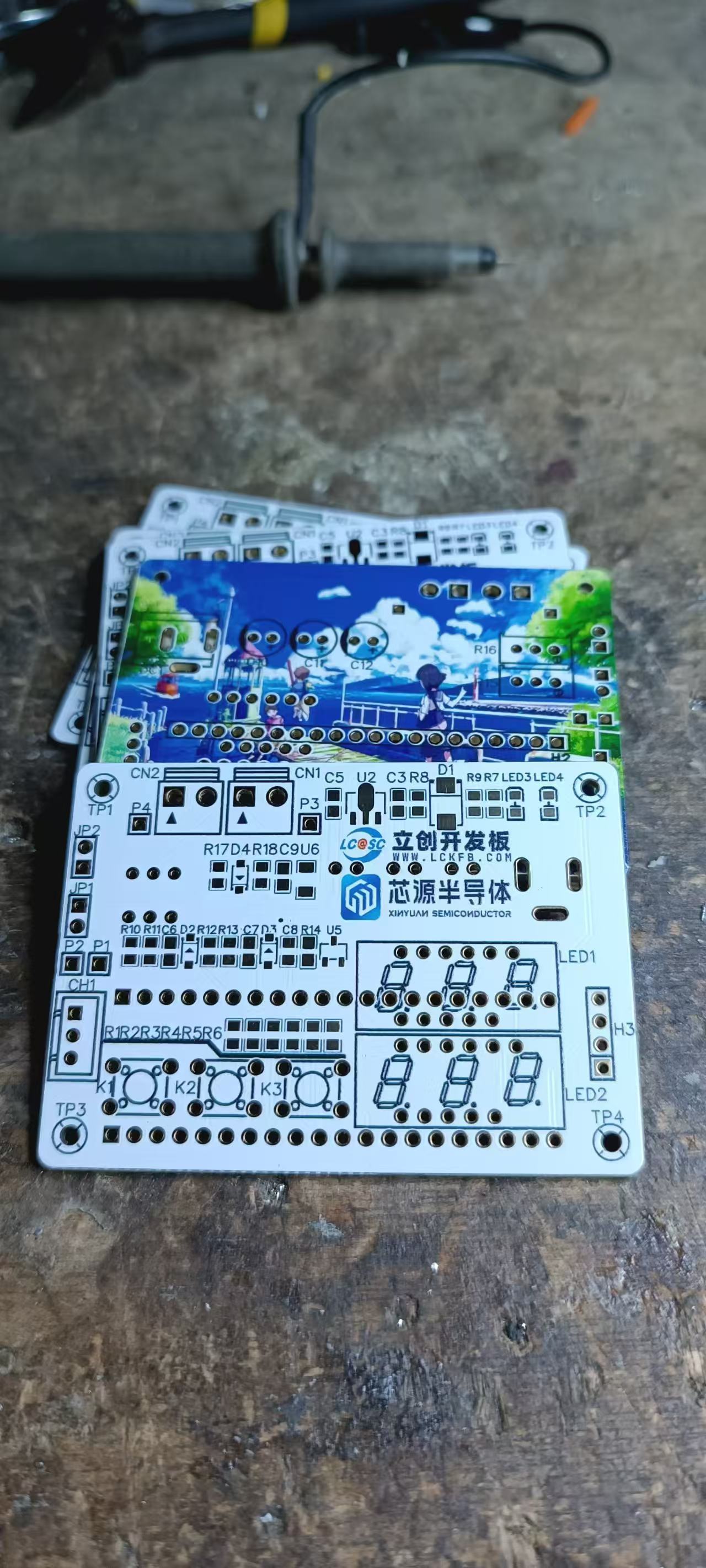
All the components used this time are plug-in type. Below are pictures of my soldering process. A family photo
of all the components connected
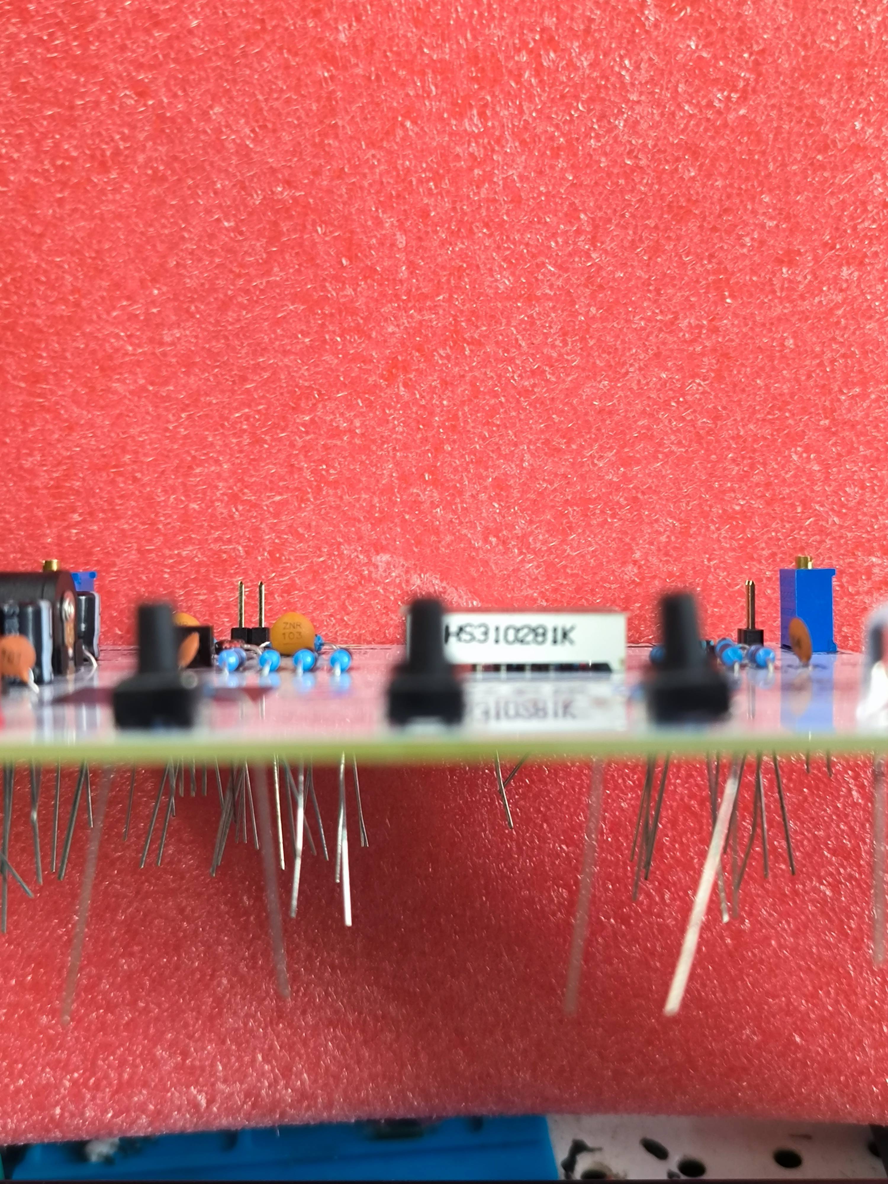
. No! A few plug-ins are still missing

because they haven't arrived. The design is quite casual, and the color silkscreen function is only reserved for the LCSC development board and Sinyuan Semiconductor.
The PCB is basically based on the official design, including the placement, layout, and routing.
The hardware power supply uses DC-DC input voltage of 5V-12V. Now
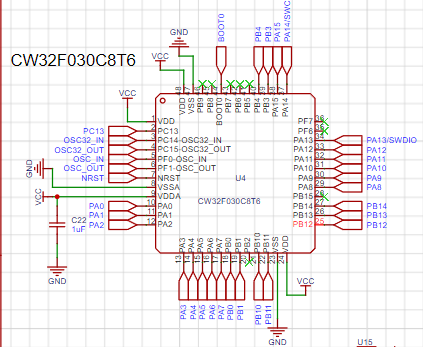
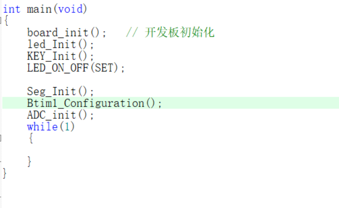
for the key point: This 32-bit chip has: a 12-bit high-speed ADC that can reach ±1.0LSB INL 11.3ENOB, and multiple Vref reference voltages. The STM32 we commonly use only supports VDD=Vref. This system uses a built-in 1.5V reference voltage, which can be configured via the program. However
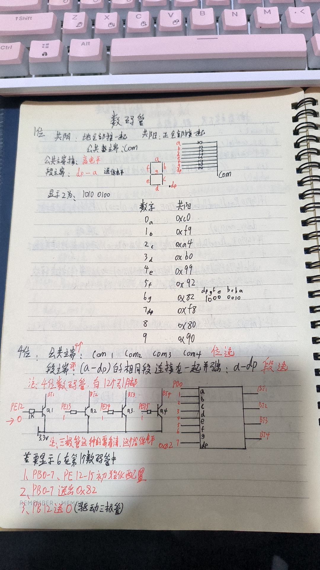
, a mistake was made in component procurement; common-cathode digital tubes were intended, but common-anode ones were mistakenly purchased. I mentioned that the digital tubes were malfunctioning after downloading the program, and after investigation, the problem turned out to be the incorrect procurement. The following is a modified part of the program for a common anode digital tube:
/* Common anode digital tube encoding table:
0xc0 0xf9 0xa4 0xb0 0x99 0x92 0x82 0xf8 0x80 0x90
0 1 2 3 4 5 6 7 8 9
0x40 0x79 0x24 0x30 0x19 0x12 0x02 0x78 0x00 0x60
0. 1. 2. 3. 4. 5. 6. 7. 8. 9.
0x3f 0xbf
0 0 1 1 1 1 1 1 1 1011 1111
dp GFEDCBA
*/
uint8_t Seg_Table[21] = {0xc0, 0xf9, 0xa4, 0xb0, 0x99, 0x92, 0x82, 0xf8, 0x80, 0x90,
0x40, 0x79, 0x24, 0x30, 0x19, 0x12, 0x02, 0x78, 0x00, 0x60,0x08};// 0x08:A.
// Common terminal settings:
/**
* @brief Close all common terminals
*
*/
void Close_Com(void)
{
GPIO_WritePin(CW_GPIOA,GPIO_PIN_8,GPIO_Pin_RESET);
GPIO_WritePin(CW_GPIOB,GPIO_PIN_3,GPIO_Pin_RESET);
GPIO_WritePin(CW_GPIOB,GPIO_PIN_4,GPIO_Pin_RESET);
GPIO_WritePin(CW_GPIOA,GPIO_PIN_11,GPIO_Pin_RESET);
GPIO_WritePin(CW_GPIOA,GPIO_PIN_12,GPIO_Pin_RESET);
GPIO_WritePin(CW_GPIOA,GPIO_PIN_15,GPIO_Pin_RESET);
} // Modification switch(Pos)
in Seg_Dis function { case 0: GPIO_WritePin(CW_GPIOA,GPIO_PIN_8,GPIO_Pin_SET); //PA8,COM1 break; case 1: GPIO_WritePin(CW_GPIOA,GPIO_PIN_11,GPIO_Pin_SET); //PA9,COM2 break; case 2: GPIO_WritePin(CW_GPIOA,GPIO_PIN_12,GPIO_Pin_SET); //PA10,COM3 break; case 3: GPIO_WritePin(CW_GPIOA,GPIO_PIN_15,GPIO_Pin_SET); //PA11,COM4 break; case 4: GPIO_WritePin(CW_GPIOB,GPIO_PIN_3,GPIO_Pin_SET); //PA12,COM5 break; case 5: GPIO_WritePin(CW_GPIOB,GPIO_PIN_4,GPIO_Pin_SET); //PA15,COM6 break; default: break; } Just change all of them to common cathode and it's OK.
Actually, understanding digital tube displays is quite simple. I'll paste some notes from my school days. Back then, I used I/O ports to drive transistors, and the transistors drove the digital tubes. I also used the STM32's PB4 pin, which needs to be configured for multiplexing to be used as a regular GPIO.
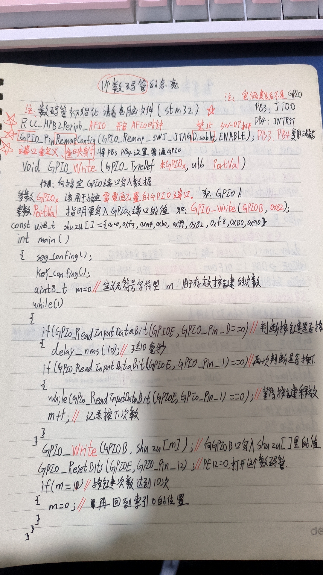
The program is fully commented to make it easier for beginners to understand. Please download the attached program for reference.
That's about it. I wish myself and everyone else continued success!
Voltage and Ammeter Project.zip
Demo video.mp4
PDF_CW32-Voltage and Current Meter.zip
Altium_CW32-Voltage and Current Meter.zip
PADS_CW32-Voltage and Current Meter.zip
BOM_CW32-Voltage and Current Meter.xlsx
92629
CW32 Voltmeter and Ammeter Training Camp Project
A CW32 voltage and current meter replica based on the CW32 voltage and current meter training camp.
Project Introduction: This project
describes a miniaturized (all-surface-mount design) integrated voltage and current meter based on the CW32 voltmeter and ammeter training program. We hope this successful experience will provide a unique perspective for enthusiasts.
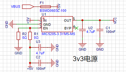
1. The power supply circuit
uses a common 3.3V linear regulated power supply to power the chip and digital display.
2. Advantages of CW32
: Wide operating temperature range: -40~105℃;
Wide operating voltage: 1.65V~5.5V (STM32 only supports 3.3V systems)
; Strong anti-interference: HBM ESD 8KV; All ESD reliability reaches the highest international standard level (STM32 ESD 2KV)
; Project focus - Better ADC: 12-bit high-speed ADC, achieving ±1.0LSB INL 11.3ENOB; Multiple Vref reference voltages... (STM32 only supports VDD=Vref);
Stable and reliable eFLASH technology. (Flash0 pending)
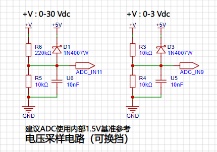
3. The voltage sampling circuit
uses a voltage divider circuit to achieve high voltage acquisition. It is designed to acquire up to 100V, but the current configuration allows for acquisition of 0-30V.
4. The current sampling circuit
uses a low-side current sampling circuit for current detection. The low-side of the sampling circuit shares a common ground with the development board's meter interface .

5. The digital tube driver
uses a digital tube as the display unit.

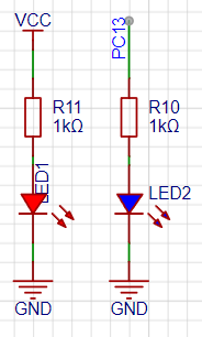
6. Indicator lights:
An additional power indicator and an IO working indicator light are designed.
7. Button circuit.

8. TL431 circuit design for voltage measurement calibration:
An additional TL431 circuit is added to provide a 2.5V reference voltage, which can be used to provide an external voltage reference for calibrating the AD converter.

Voltage Testing:
1. 5V charger voltage test (error approximately 0.3V)

2. Battery voltage measurement test (error approximately 0.4V)

PDF_cw32 Voltmeter and Ammeter Training Camp Project.zip
Altium_cw32 Voltmeter and Ammeter Training Camp Project.zip
PADS_cw32 Voltmeter and Ammeter Training Camp Project.zip
BOM_cw32 Voltage and Current Meter Training Camp Project.xlsx
92630
electronic
 If the design is sound, I feel this is the coolest circuit I've ever designed. It took about half a month to complete, uses a four-layer board, isolates the drive and control layers, and retains debugging interfaces for easy debugging. I hope someone can verify this; it should be fine. At least I've tested each module individually without problems.
 Video Link:
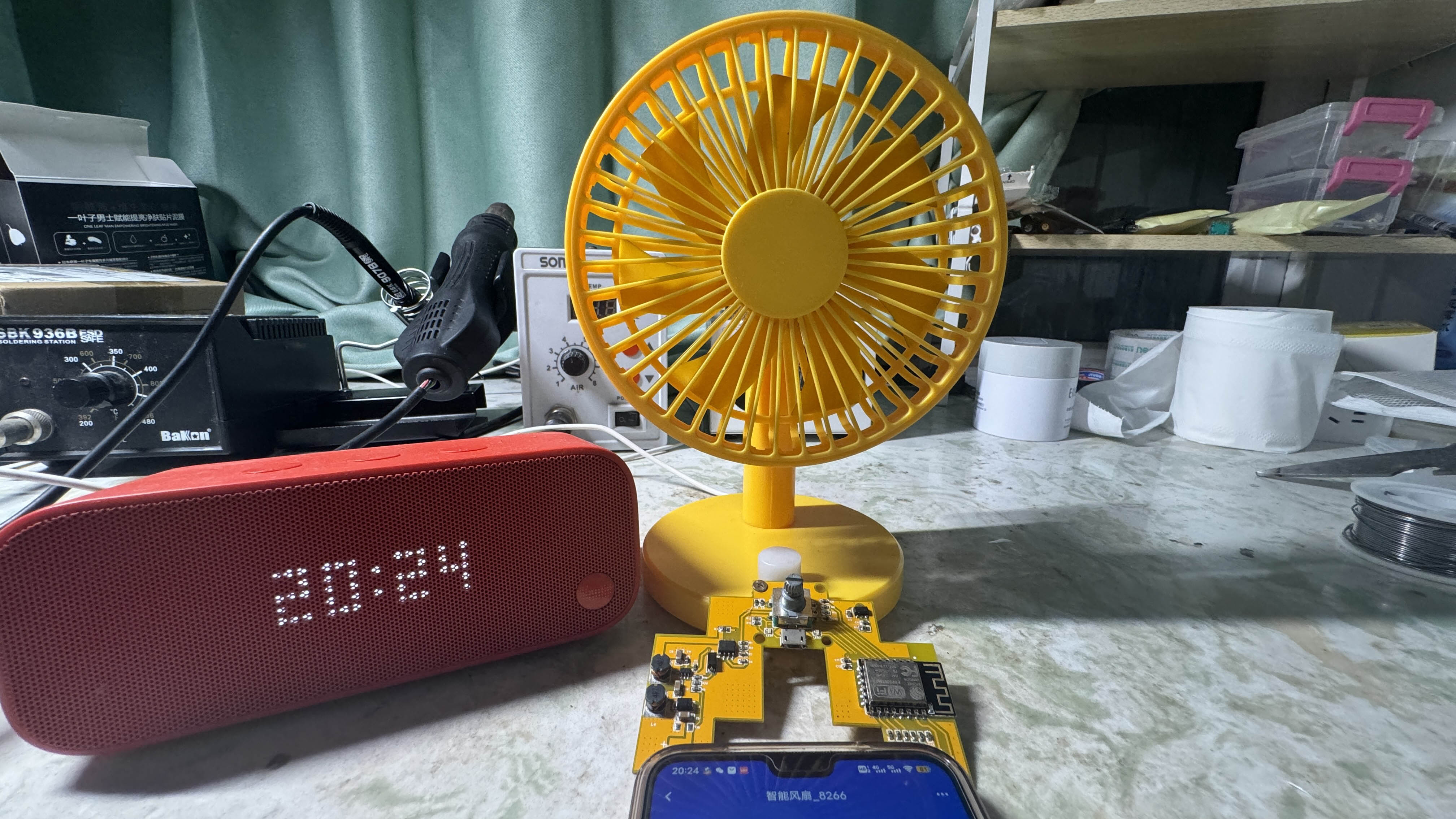
 So how can we control it with a microcontroller?
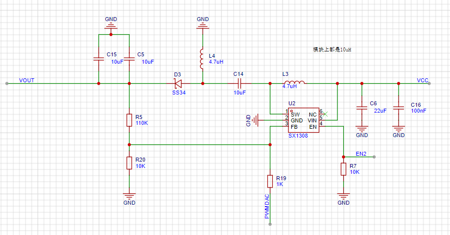 the microcontroller only needs to change the voltage at FB, and the SX1308 can adjust the output voltage to achieve the boost effect.
  The software
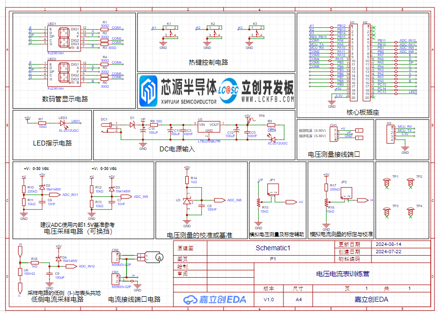
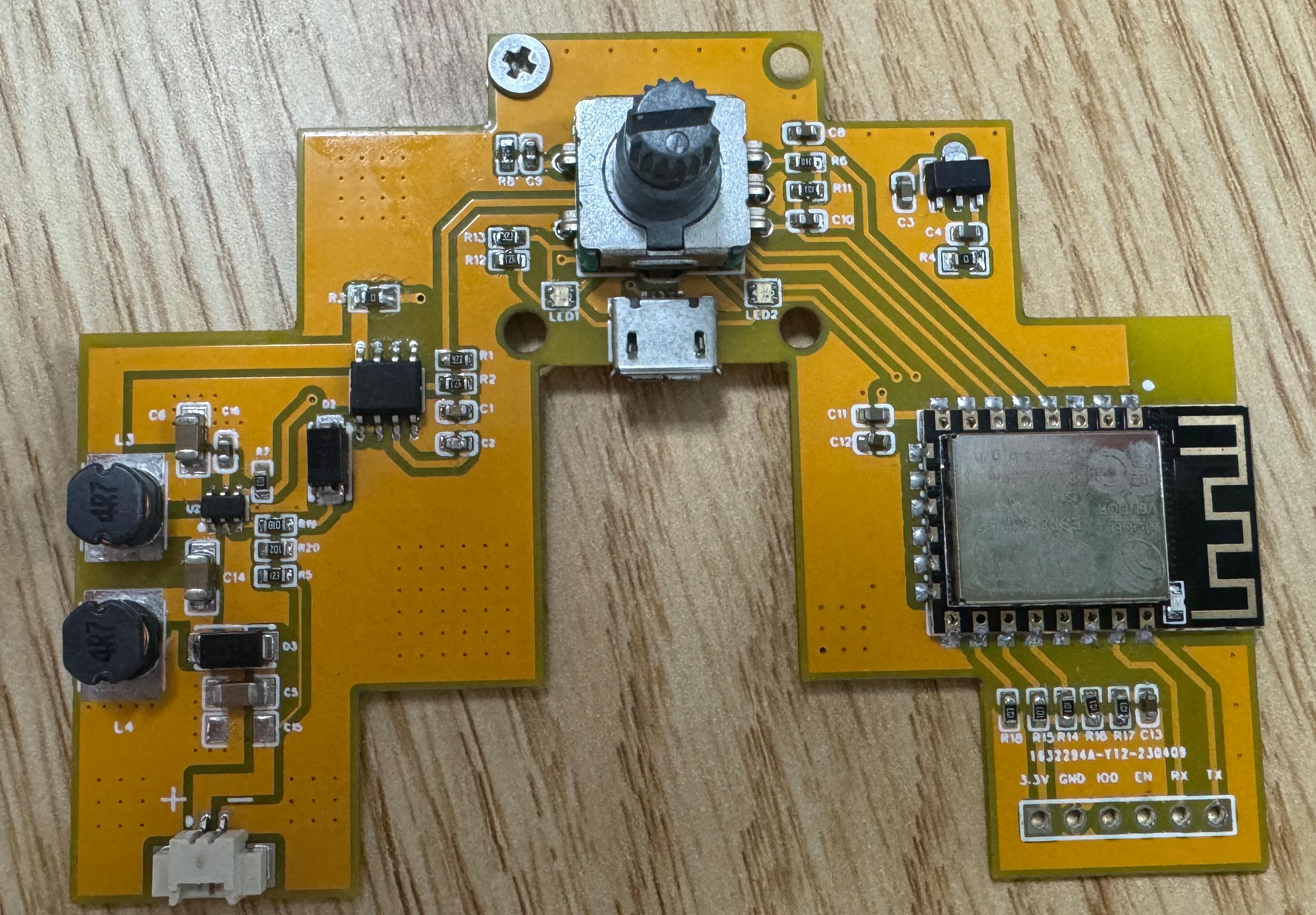
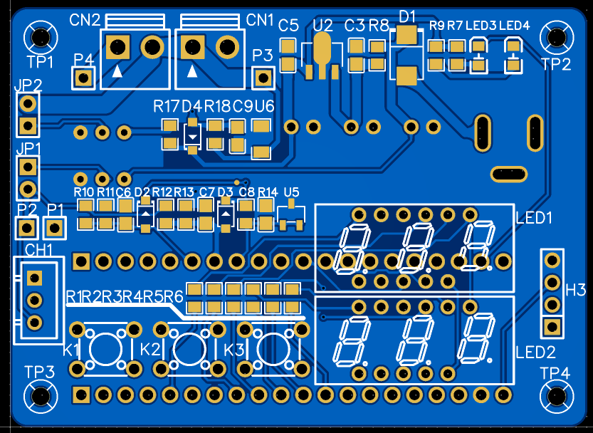 This design primarily uses 0805 surface-mount packages, significantly reducing the size of the product.
  The development board is placed on the back of the board; due to a momentary oversight, the orientation is reversed, but this does not affect its practical use.
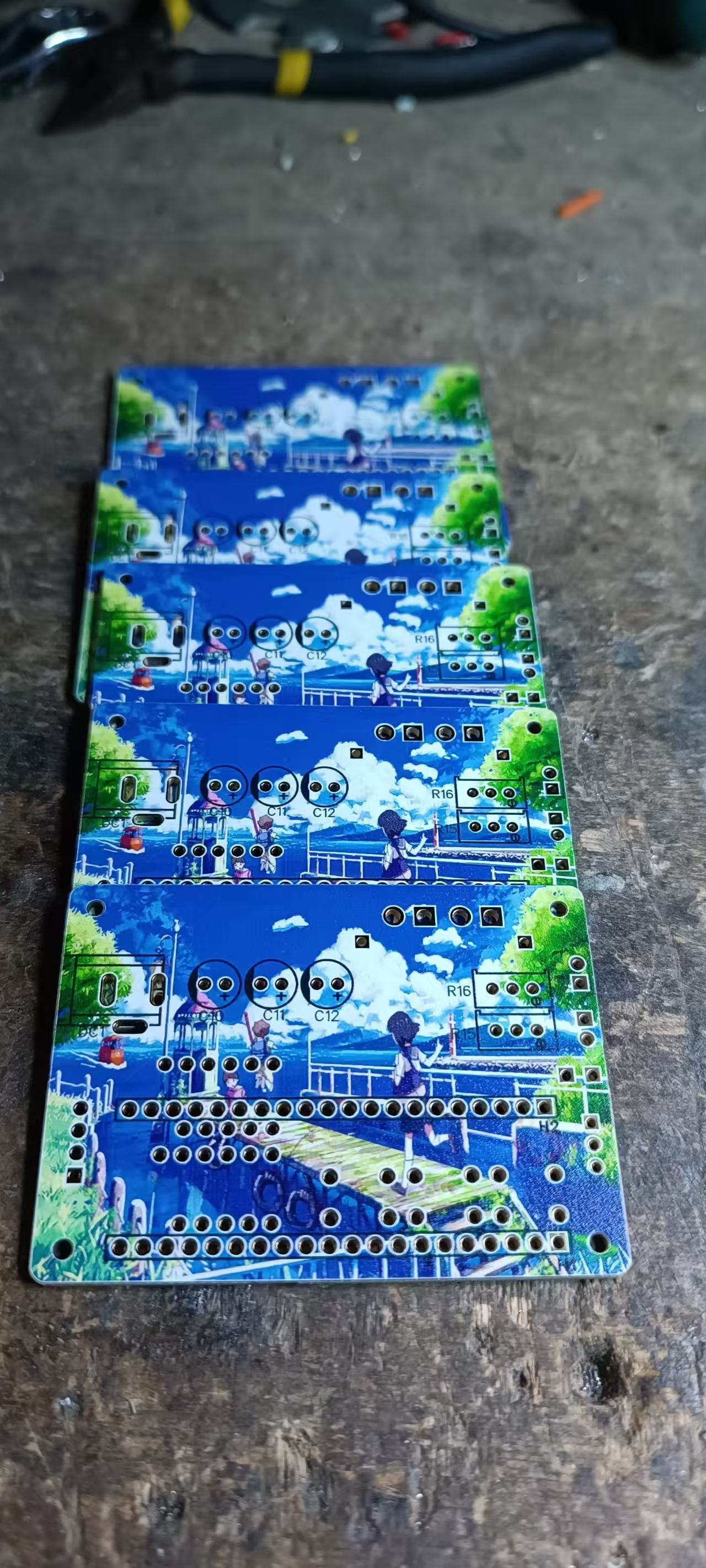
 Notes
Notes 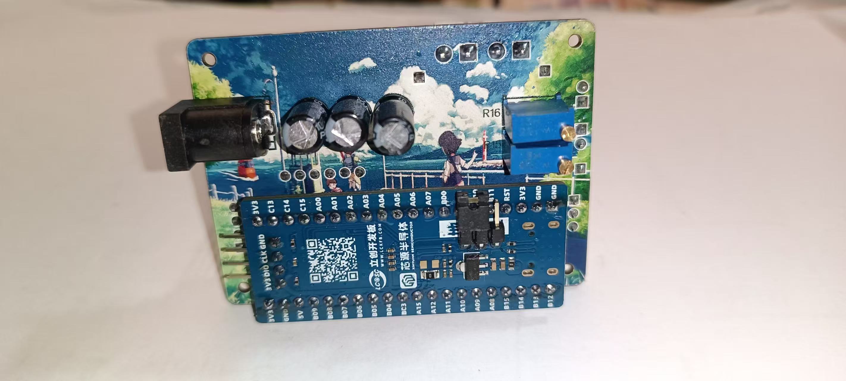 : This section explains some precautions to take during the creation of the project (optional).
 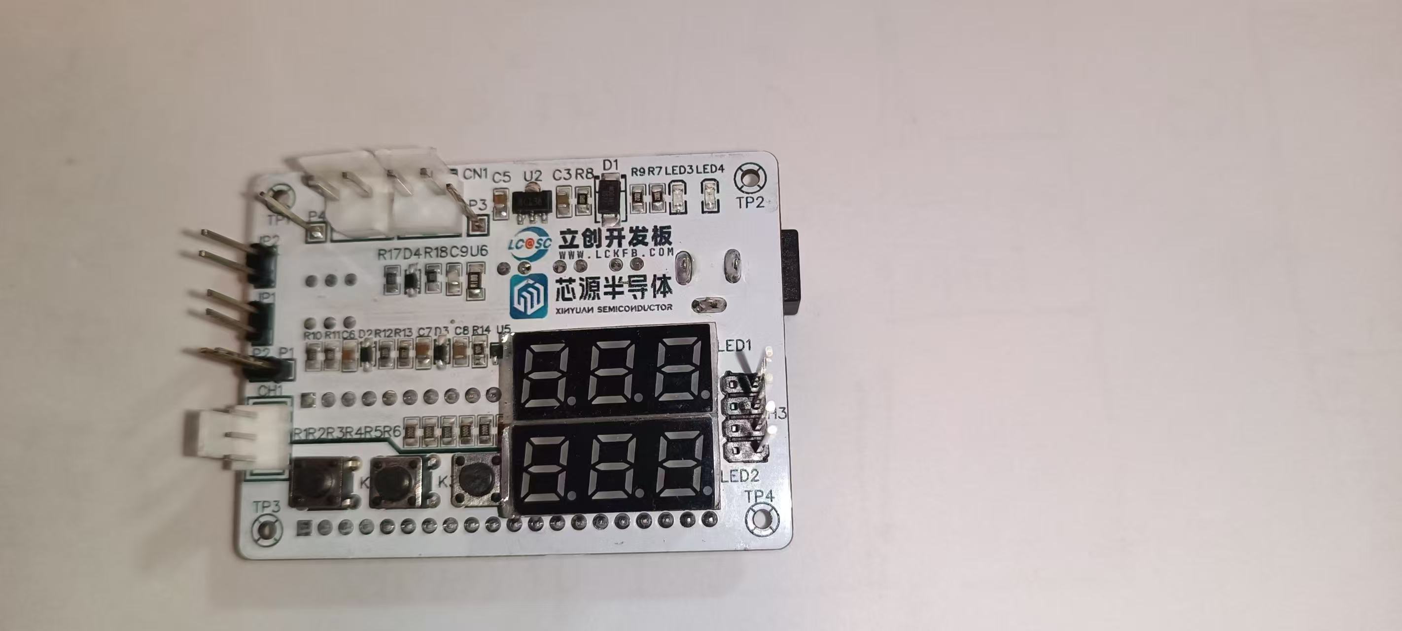 Demo Video
 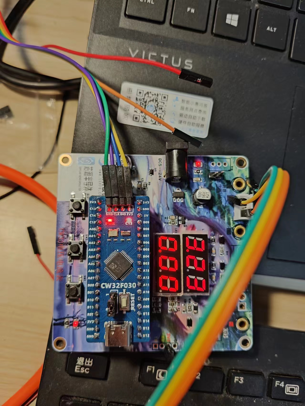 The hardware of the voltage and current meter based on SW32F030 is as follows:
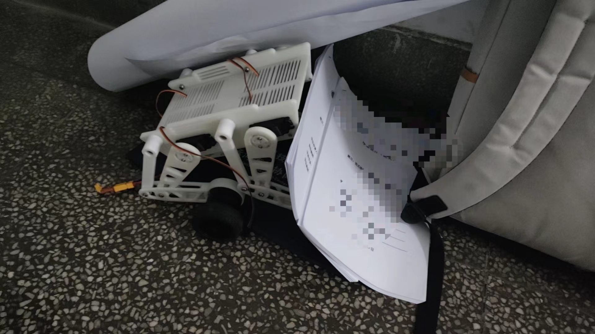
 The project doesn't involve circuitry and comes in two sizes, compatible with most development boards on the market.
 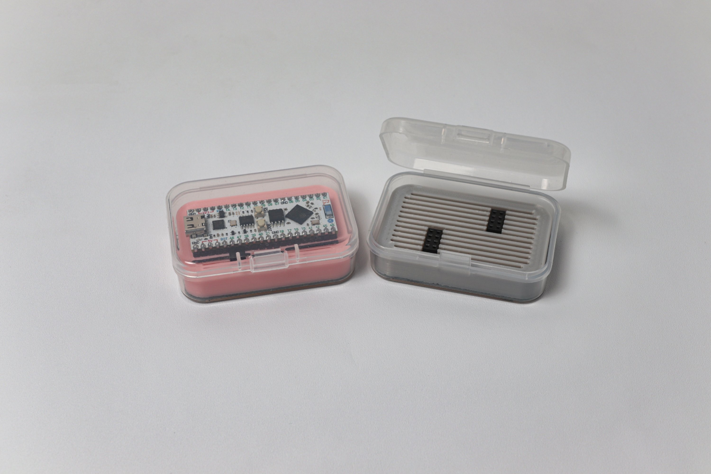 The storage box consists of a transparent plastic box, a 3D-printed support, and a PCB base with surface-mount headers.
  Care should be taken to control the temperature of the 3D-printed parts to prevent stringing and cleaning difficulties.
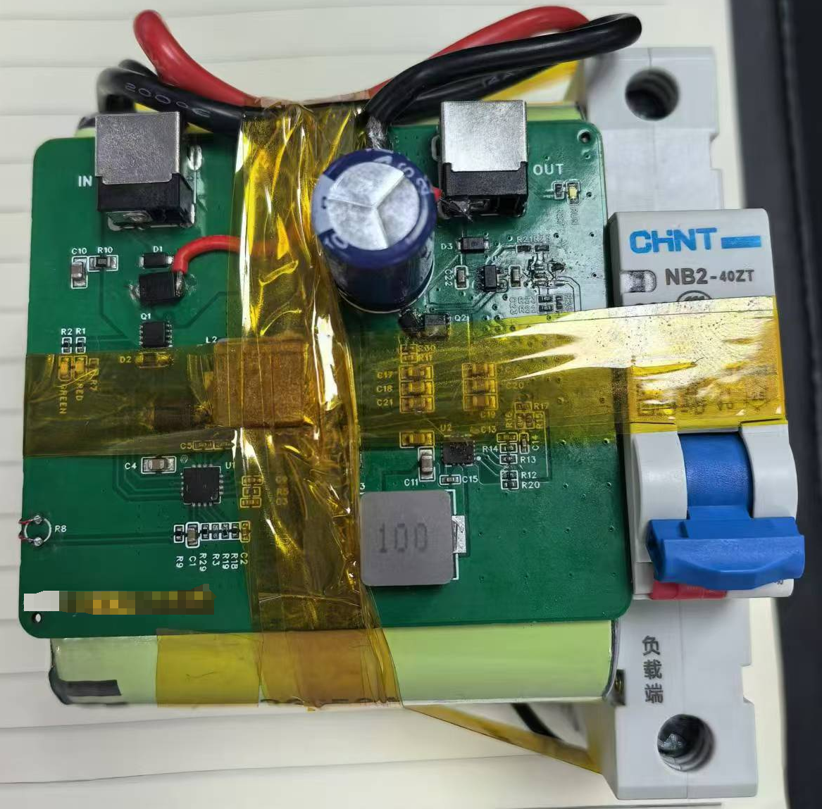


 京公网安备 11010802033920号

 M37150MC


