I. Design Background
An ADC (Analog-to-Digital Converter) is an indispensable key component in electronic systems. It converts continuous analog signals into digital signals, enabling digital processing and analysis. ADCs play a crucial role in signal conversion, measurement and data acquisition, control system input, and communication and signal processing. Their widespread application promotes the intelligent and precise control of electronic equipment across various industries, and is one of the key factors driving modern technological progress.
Digital voltmeters and ammeters combine ADC technology with circuit measurement principles, accurately converting analog voltage and current signals into digital displays for easy reading and analysis by electronic engineers. This device not only improves the accuracy and efficiency of circuit measurements but also helps engineers better understand circuit behavior, serving as a powerful tool for electronic design and troubleshooting, and playing a vital supporting role in the work of electronic engineers. In product applications, digital voltmeters ensure the accuracy and safety of circuit design, while also providing strong support for product quality control and subsequent maintenance.

Learning to design and build a digital voltmeter and ammeter is highly beneficial for improving one's professional skills. This digital voltmeter and ammeter project covers multiple aspects, including microcontroller circuit design and implementation, signal acquisition and processing circuit design, user interface development and optimization, and product appearance design. It integrates knowledge from multiple fields such as electronics, microcontroller programming, circuit design, and industrial design. Considering the learning pace and knowledge absorption capacity of beginners, we have specially launched this introductory-level digital voltmeter and ammeter project, which is very suitable for beginners in electronics and those who want to learn more about microcontroller applications. This project has the following highlights:
it adopts a core board plus expansion board design concept and uses plug-in device design, making learning simpler and exploration more in-depth;
the core board uses the domestic Wuhan Xinyuan Semiconductor CW32 as the main controller, while also being compatible with other similar development boards; however, the CW32 has advantages.
The project is highly comprehensive and practical, and after completion, it can be used as a desktop instrument;
the project has abundant learning materials, including circuit design tutorials, PCB design, code programming learning, and training for engineers' debugging skills.
II. Hardware Design
1. Power Supply Circuit
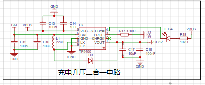

Powered by a lithium battery and USB. Supports charging and discharging.
2. MCU Selection Analysis
When selecting an MCU (Microcontroller Unit) for this project, multiple aspects need to be considered to ensure that the selected MCU meets the project requirements.
Clearly define your project requirements: Understand clearly how much computing power the project needs, including clock speed, processor core type, and whether a floating-point unit is required.
Identify the required I/O ports and important peripherals, such as ADC peripherals. Since this is a development board project, the main purpose is debugging and learning; therefore, there are no strict limitations on the number of I/O ports: i.e., the resulting cost issues are not considered.
Key advantages of CW32 in this project
: Wide operating temperature range: -40~105℃;
Wide operating voltage range: 1.65V~5.5V (STM32 only supports 3.3V systems);
Strong anti-interference: HBM ESD 8KV; All ESD reliability reaches the highest international standard level (STM32 ESD 2KV);
Project focus - Better ADC: 12-bit high-speed ADC, achieving ±1.0LSB INL 11.3ENOB; Multiple Vref reference voltages... (STM32 only supports VDD=Vref);
Stable and reliable eFLASH technology. (Flash0 pending).
A detailed explanation of these advantages will be provided in the chapters on ADC sampling and related extensions.

3. Voltage Sampling Circuit:
This project uses a voltage divider circuit to achieve high voltage acquisition. The design can acquire voltages up to 100V, and the current configuration acquires voltages from 0-30V.

The voltage divider resistors in this project are designed to be 220K+10K, therefore the voltage division ratio is 22:1 (ADC_IN11).
The voltage divider resistor selection
is based on the maximum measured voltage; for safety reasons, this project uses 30V (the actual maximum display value can be 99.9V or 100V).
The ADC reference voltage in this project is 1.5V, which can be configured through the program.
To reduce power consumption in the sampling circuit, the low-side resistor (R7) is usually selected as 10K based on experience.
The high-side resistance of the voltage divider resistors can then be calculated using the above parameters.
The required voltage division ratio is calculated as follows: ADC reference voltage: Design input voltage, calculated using known parameters as 1.5V/30V=0.05.
The high-side resistance is calculated as: Low-side resistance/voltage division ratio, calculated using known parameters as 10K/0.05=200K.
A standard resistor is selected: A resistor slightly higher than the calculated value is chosen; the calculated value is 200K. We usually choose E24 series resistors, therefore in this project, 220K is selected, which is greater than 200K and closest to the calculated value.
If, in actual use, the voltage to be measured is lower than 2/3 of the module's design voltage (66V), the voltage divider resistor can be replaced and the program modified to improve measurement accuracy. The following example illustrates this:
Assuming the measured voltage is no higher than 24V and other parameters remain unchanged,
calculations show 1.5V/24V = 0.0625, 10K/0.0625 = 160K. 160K is a standard E24 resistor and can be directly selected, or a higher value 180K can be chosen with some redundancy.
If, in actual use, the voltage to be measured is higher than the module's 99V design voltage, a different resistor can be selected. To expand the voltage measurement range, you can choose to replace the voltage divider resistor or modify the reference voltage. Here's a case study:
Assuming the measured voltage is 160V, we can choose to increase the voltage reference to expand the range.
Given that the voltage division ratio of the selected resistor is 0.0145, we can calculate 160V * 0.0145 = 2.32V using the formula. Therefore, we can choose a 2.5V voltage reference to expand the range (increasing the range will reduce accuracy).
Considering the potential fluctuations in the measured power supply, a 10nF filter capacitor is connected in parallel with the low-side voltage divider resistor to improve measurement stability.
Diode clamping ensures MCU safety
. In designing this project, I added an additional 1N4148 (D1, etc.) as a clamping diode to the sampling circuit. This helps avoid damage to the chip pins due to incorrect voltage input during learning and debugging. Diode clamping is an important electronic circuit design technique; its main function is to protect the circuit by limiting the voltage amplitude, preventing damage or malfunction caused by excessively large or small signals.
In circuit design, clamping refers to limiting voltage. Diode clamping specifically refers to the technique of using a diode to limit the potential at a point in a circuit.
Diode clamping primarily utilizes the unidirectional conductivity of a diode. When the voltage across the positive terminal of a diode is greater than the voltage across its negative terminal and the diode is turned on, the voltage across the diode is limited to its voltage drop across the diode. Typically, the voltage drop across a silicon diode is about 0.7V.
The clamping process involves forcibly pulling the clamped potential towards the reference terminal through the clamping action of the diode, thereby limiting the potential. Clamping does not change the waveform of the original signal; it only raises or lowers the reference potential of the signal.
Depending on the diode connection method, clamping circuits can be divided into positive clamping circuits and negative clamping circuits. This project only designs positive clamping.
Positive clamping circuit: When the positive terminal of the diode is grounded, it is a positive clamping circuit. During the positive half-cycle, the diode is cut off; during the negative half-cycle, the diode conducts, and the capacitor is charged to a certain voltage, limiting the output voltage within a certain range.
Negative clamping circuit: When the negative terminal of the diode is grounded, it is a negative clamping circuit. The working principle is the opposite of the positive clamping circuit.
Adding a voltage sampling circuit to achieve range switching:
In this project, an additional voltage sampling circuit was added. Therefore, we can discuss the significance of range switching for improving measurement accuracy. Multimeters often have multiple range settings to achieve more accurate measurements. By adjusting different ranges, the optimal measurement accuracy of the measured point within the corresponding range can be obtained.
This project requires a combination of hardware and software to achieve this function. When we first use the ADC_IN11 channel mentioned earlier to measure voltages below 30V... If the measured voltage is within 0~3V, use the ADC_IN9 channel for measurement. At this time, due to the reduced voltage division ratio, the measurement accuracy is greatly improved.
There are many ways to implement gear shifting, and the development board design provides more design possibilities.
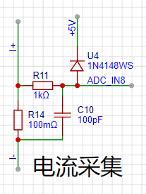
4. Current Sampling Circuit This project uses a low-side current sampling circuit for current detection. When
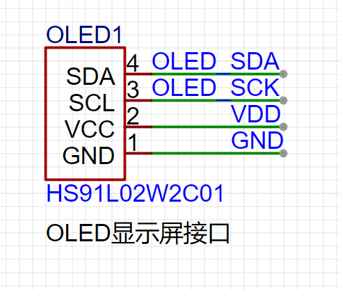
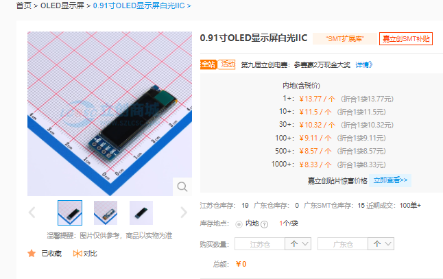
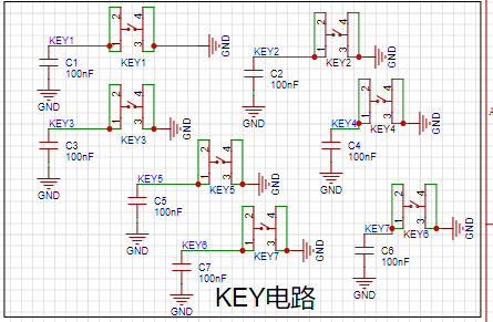
the low-side of the sampling circuit shares a common ground with the development board's meter interface , please do not solder R14!!! Design Analysis: The sampling current designed in this project is 3A, and the selected sampling resistor (R0) is 100mΩ. The sampling selection mainly needs to consider the following aspects: the maximum value of the pre-designed measurement current, which in this project is the voltage difference brought by the 3A current sensing resistor. It is generally not recommended to exceed 0.5V. The power consumption of the current sensing resistor should be selected according to this parameter. Considering the power consumption (temperature) problem under high current, a 1W packaged metal wire-wound resistor was selected in this project. The voltage amplification factor on the current sensing resistor: No operational amplifier was used to build the amplification circuit in this project, so the factor is 1. Then, the current sensing resistance value can be calculated using the above parameters. Selection: Since this project... Since no amplifier circuit is used, a larger sampling resistor is needed to obtain a higher measured voltage for measurement. Considering that a larger resistor would result in a larger voltage drop and higher power consumption, an unlimited selection of a larger resistor is not feasible. This project uses a 1W package resistor, corresponding to a power rise of 1W. Based on the above data, a 100mΩ current sensing resistor was chosen. According to the formula, 3A * 100mΩ = 300mV, 900mW. To handle different operating environments, especially high-current scenarios, the R0 resistor can be replaced with constantan wire or a shunt. The choice of alternative can be based on the actual application scenario. For safety and educational purposes, this project will not discuss measurements exceeding 3A, but the principle remains the same. 5. OLED Driver: This project uses a digital tube as the display unit. A 0.91-inch 128x32 monochrome screen is used here because it is suitable for displaying data. We recommend purchasing from LCSC Mall. The circuit diagram is shown below: Plug and play! This screen is basically the cheapest. 7. Button Circuit Design There are various design methods for the button control circuit. Thanks to the CW32's internal I/O ports which can be configured with pull-up and pull-down resistors, the button control circuit on the outside of the chip does not need to be configured. One end of the button is connected to the MCU's I/O, and the other end is grounded. When the button is pressed, the I/O is pulled low. 8. TL431 Circuit Design for Voltage Measurement and Calibration This project adds an extra TL431 circuit to provide a 2.5V reference voltage, which can be used to provide the chip with an external voltage reference for calibrating the AD. From a product design perspective, due to the inherent ADC performance advantages of the CW32, this circuit is not necessary. This circuit is designed on the development board for learning related application principles. III. Software Design 3.1. Software Development Overview 3.1.1. Essential Embedded Knowledge Points Embedded software development, as an interdisciplinary field of computer science and electrical engineering, requires developers to possess a range of professional knowledge and skills. Essential knowledge for CW32-based embedded software development includes the following: Programming Languages: Proficiency in C (C++) is crucial, as it's the most commonly used programming language in embedded systems due to its direct hardware access capabilities and high code execution efficiency. Understanding of assembly language is necessary for writing low-level drivers, interrupt handlers, and high-performance code segments. A basic understanding of other programming languages such as Python and Java is required for specific situations. Familiarity with the CW32 standard library is essential. Data Structures and Algorithms: Familiarity with various data structures, such as arrays, linked lists, stacks, and queues, as well as common algorithms like sorting, searching, and recursion. The ability to select appropriate data structures and algorithms based on the resource constraints of the embedded system is required. Computer Architecture: Understanding of processor architectures, such as ARM and x86, as well as instruction sets and memory management is essential. Familiarity with the hardware components of embedded systems, such as microcontrollers, FPGAs, and DSPs, is required. The ability to readily refer to the CW32 embedded chip's datasheet and user manual to understand the operating principles of required peripherals is also essential. Embedded Operating Systems (In-depth Knowledge): Master commonly used embedded operating systems such as μC/OS and FreeRTOS, and understand their kernel, process management, memory management, device management, and file system principles. Be able to design and manage operating system tasks to meet the needs of specific applications. Hardware Interfaces and Peripherals: Be familiar with common hardware interfaces such as GPIO, serial ports, SPI, and I2C, and be able to write corresponding drivers. Understand commonly used hardware devices in embedded systems, such as sensors, actuators, and communication modules, and be able to interact with them. Development Tools and Environment: Be proficient in using integrated development environments (IDEs) such as KEIL, IAR, and Visual Studio for software development and debugging. Master the use of cross-compilers to compile programs that can run on target hardware on the development computer. Be familiar with the use of debuggers, and be able to perform software breakpoint debugging, single-step execution, and variable viewing. System Analysis and Design: Be able to perform project requirements analysis and transform requirements into software functional requirements. Master the principles and methods of software architecture design, and be able to design efficient and maintainable software systems. Understand the real-time requirements of embedded systems and be able to design software systems that meet these requirements. Testing and Verification: Master the methods and techniques of unit testing, integration testing, and system testing, and be able to perform comprehensive testing of software to ensure its correctness and stability.

Understanding the reliability requirements of embedded systems and being able to perform software reliability testing and verification are essential. Only by fully mastering this knowledge and possessing the ability to continuously learn can one become an excellent embedded software developer.
3.1.2 Getting Started
Install the development environment (MDK 5.33 is recommended), DAPLINK downloader, and firmware library. The firmware library can be downloaded from the official website: www.whxy.com. Common debuggers such as STLINK, DAPLINK, PWLINK, WCHLINK, JLINK, etc., that support Cortex-M are acceptable.
3.2. Setting up the Development Environment
3.2.1 Installing Keil
Recently, Keil officially announced a new version of Keil MDK: the MDK Community Edition. This version has the following main features:
It is available for non-commercial free evaluation and use by electronics enthusiasts, students, scholars, and other groups.
There are no code size limitations.
It supports Arm Compiler 6: providing streamlined code and powerful performance for all Arm Cortex-M based products.
Access to over 9,500 microcontroller devices supporting Cortex-M processors.
The CMSIS standard framework for Arm-based microcontrollers.
A large number of free middleware options (keil RTX5, lwIP, CMSIS-FreeRTOS, etc.).
3.2. Code Writing
The program is written in C language. The main program implementation code is as follows:
int main()
{
RCC_Configuration(); //System clock 64M
KEYGPIO_Init();
GPIO_WritePin(CW_GPIOC,GPIO_PIN_13,GPIO_Pin_RESET);
OLED_Init();
OLED_Clear();
OLED_DisplayTurn(1);
Btim1_Init();
ADC_init();
read_vol_cur_calibration();
ComputeK();
while(1)
{
if(BrushFlag==1)
{
DisplayBuff();
OLED_Refresh();
BrushFlag=0;
}
if(timecount>= 200) //Change the digital tube display value once every 300ms//
{
timecount=0;
Volt_Cal();
BrushFlag=1;
}
}
III
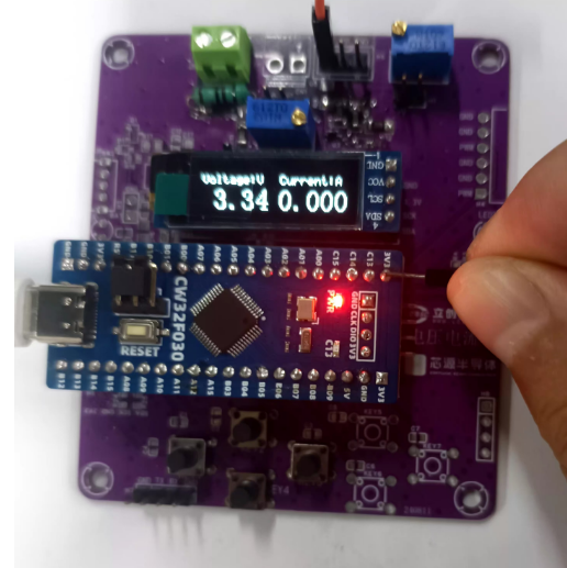
. Results Demonstration:
Initial values are very accurate:

There is a certain deviation when measuring a current of 1.4A,

and there is also a deviation when measuring a voltage of 3.3V.
A complete video demonstration can be found on Bilibili:
https://www.bilibili.com/video/BV1wbWreBEg3/?vd_source=24f1befd6441a33d7b240715cb07c7b5


 京公网安备 11010802033920号

 RFM0947-10


