 To avoid introducing DC-DC ripple interference and reduce project costs due to the high voltage difference, this replication project uses an LDO as the power supply, specifically the SE8550K2-HF. Due to my oversight, the actual power supply used was the SE8533K2-HF, the difference being that the output voltage changes from 5V to 3.3V. Initial assessment suggests this will not significantly affect subsequent circuitry. Compared to the original project, only the current-limiting resistor at the TL431 reference voltage needs to be replaced from 1kΩ to 800Ω.
  In this project, a TL431 is chosen to provide a 2.5V reference voltage to the CW32 ADC. Since the CW32 has built-in 1.5V and 2.5V reference voltages that can be configured in the program, the main purpose of this circuit design is to learn the relevant principles.
 Since the LDO provides a voltage of 3.3V in this project, based on the above calculation, resistors with an Ω or lower and a package size greater than 0.08W should be selected.
 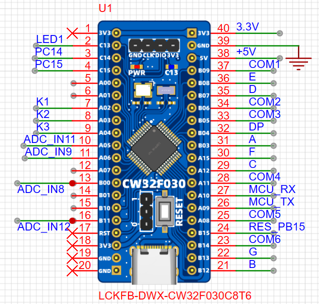 In this project, the CW32F030C8T6 has a wide operating voltage range of 1.65V~5.5V, a 12-bit successive approximation ADC, and four reference voltage sources (VDDA power supply voltage, PB0 pin voltage, built-in 1.5V reference voltage, and built-in 2.5V reference voltage). The voltage
 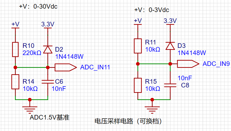 is shown in the figure. The voltage measurement circuit has two ranges to choose from. During measurement, according to the program settings, the more suitable measurement result is selected to improve the measurement accuracy. When the ADC internal reference voltage is selected as 1.5V, the maximum measurement voltage at the high range is calculated based on the voltage divider resistors, and the maximum measurement voltage at the low range is 3V.
 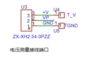 In the figure, U4, U5, U8, and U9 correspond to the 2mm banana plug interface on the PCB, used to insert multimeter probes for easy verification of measurement accuracy and calibration. U3, CN1, and CN2 are the corresponding connection ports for the measured values. +V connects to the voltage to be measured, T_V connects to the red probe of the multimeter, and TGND connects to the black probe. CN2 is connected to the current to be measured; the current flows in from I+ and out from I- on CN2. The red probe of the multimeter is inserted into TI+, and the black probe is inserted into TGND .
 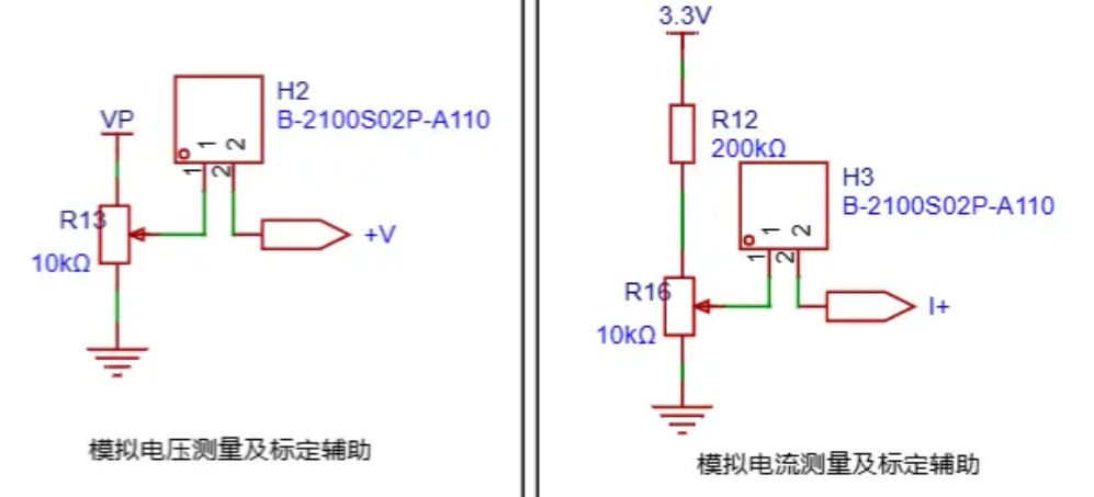 An analog voltage is obtained through an adjustable potentiometer for measuring ADC accuracy and for calibration. A jumper cap needs to be connected during use. When using analog current measurement, the 100mΩ sampling resistor cannot be soldered
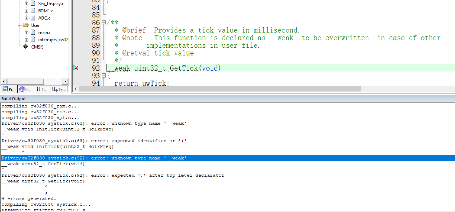
 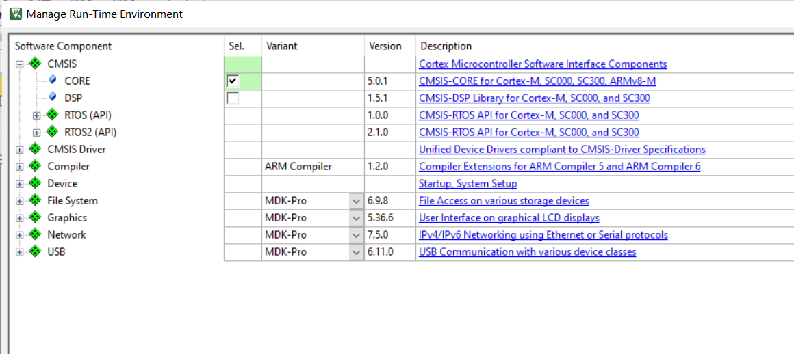 for this project may encounter errors during compilation. Removing __weak will stop the errors. Due to the lack of a DC power line and the fact that the PCB was not traced from the 3.3V power supply, the voltage measurement cannot be verified at this time.

All reference designs on this site are sourced from major semiconductor manufacturers or collected online for learning and research. The copyright belongs to the semiconductor manufacturer or the original author. If you believe that the reference design of this site infringes upon your relevant rights and interests, please send us a rights notice. As a neutral platform service provider, we will take measures to delete the relevant content in accordance with relevant laws after receiving the relevant notice from the rights holder. Please send relevant notifications to email: bbs_service@eeworld.com.cn.
It is your responsibility to test the circuit yourself and determine its suitability for you. EEWorld will not be liable for direct, indirect, special, incidental, consequential or punitive damages arising from any cause or anything connected to any reference design used.
Supported by EEWorld Datasheet
EEWorld
subscription
account

EEWorld
service
account

Automotive
development
community

Robot
development
community

About Us Customer Service Contact Information Datasheet Sitemap LatestNews


Room 1530, 15th Floor, Building B,
No.18 Zhongguancun Street,
Haidian District,
Beijing, Postal Code: 100190
China
Telephone: 008610 8235 0740
 京公网安备 11010802033920号

 LPS-100-24


