This project , a voltage and current meter based on the CW32F030 development board, is part of the LCSC Development Board Training Camp .
I. Project Description
: This project follows the LCSC training camp. As a liberal arts student, this is my first systematic encounter with PCB design and programming. The aim is to cultivate my relevant knowledge and connect with other developers. The circuit design largely follows the official schematic, with simplifications made to the current and voltage sampling circuitry. The current sampling resistor is designed to be pluggable, facilitating initial debugging and allowing for later replacement to increase the range. However, due to my limited programming skills, multiple attempts to program the current sampler failed, and I used the official program instead. I am currently still writing the relevant code. The replaceable sampling resistor design is only shared as an example of a design concept.
Compared to the official example, this design replaces many components with surface-mount components and places the development board on the back of the PCB to reduce the overall area.
I was a bit lazy and used a heating table when soldering surface-mount components.
For detailed schematic design references, please see:
1. https://oshwhub.com/li-chuang-kai-fa-ban/cw32-shu-zi-dian-ya-dian-liu-biao-kai-fa-ban-tao-jian
2. https://wiki.lckfb.com/zh-hans/dwx-cw32f030c8t6/question/
II. Circuit Design
1. Power Supply Circuit
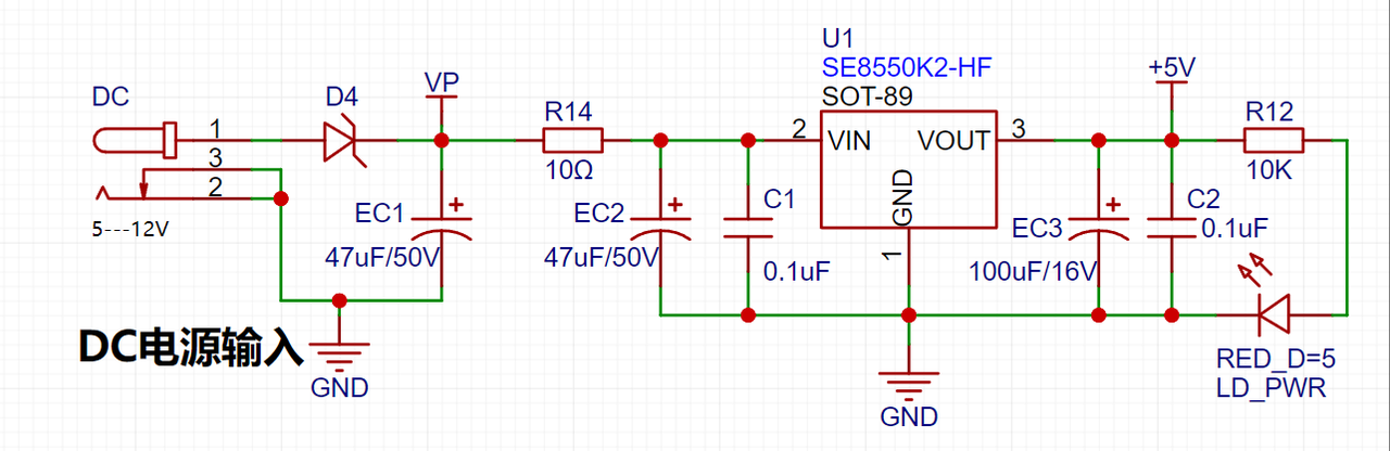
LDO (Low Dropout Linear Regulator) Selection This project uses an LDO as the power supply. Considering that most voltmeter products are used in industrial scenarios with 24V or 36V power supplies, this project selected the SE8550K2, which has a maximum input voltage of up to 40V, as the power supply. The main reason for not using a DC-DC buck converter to handle the large voltage drop is to avoid introducing DC-DC ripple interference during the design process; a secondary reason is to reduce project costs.
2. MCU Selection Analysis
To reduce the learning curve, this project uses the LCSC CW32F030C8Tx development board (core board) as the main controller. However, this doesn't mean we'll discuss this section less. From an engineer training perspective, proper main controller selection is crucial, as it affects the overall project performance. Regarding voltage and current meters, I conducted debugging and testing using STM32/CW32 and some other 32-bit microcontrollers. Here, we only compare it with the STM32F103C8T6 as a reference for device selection, primarily to provide ideas and improve understanding.
Avoid Blind Selection When selecting the MCU (microcontroller unit) for this project, multiple aspects need to be considered to ensure the chosen MCU meets project requirements.
Clearly define your project needs: Understand the required computing power, including clock speed, processor core type, and whether a floating-point unit is needed. Clearly define
the required I/O ports and important peripherals, such as ADC peripherals. Since this is a development board project, the main purpose is debugging and learning. Therefore, there are no strict limitations on the number of I/O pins; cost and other related issues are not considered.
The key advantages of the CW32 in this project include
: wide operating temperature range (-40~105℃);
wide operating voltage range (1.65V~5.5V; STM32 only supports 3.3V systems)
; strong anti-interference capability (HBM ESD 8KV); all ESD reliability meets the highest international standard (STM32 ESD 2KV)
; and a better ADC (12-bit high-speed ADC with ±1.0LSB INL 11.3ENOB, multiple Vref reference voltages... ...; (STM32 only supports VDD=Vref); and
stable and reliable eFLASH technology.
A detailed explanation of these advantages will be provided in the chapters on ADC sampling and related extensions.
The main characteristics of the CW32 ADC: This project requires a focus on the 4 reference voltage sources. (Content from the "CW32x030 User Manual")

3. Voltage Sampling Circuit:
The voltage divider resistors in this project are designed to be 220K+10K, therefore the voltage division ratio is 22:1 (ADC_IN11).
The voltage divider resistor selection
is designed to measure the maximum voltage. For safety reasons, this project uses 30V (the actual maximum display value can be 99.9V or 100V).
The ADC reference voltage is 1.5V in this project, and this reference voltage can be configured through the program.
To reduce the power consumption of the sampling circuit, the low-side resistor (R7) is usually chosen as 10K based on experience.
Then, the high-side resistance of the voltage divider resistor can be calculated using the above parameters.
The required voltage division ratio is calculated, i.e., the ADC reference voltage. The input voltage is designed; using known parameters, 1.5V/30V = 0.05 can be calculated.
The high-side resistance is calculated as the low-side resistance/voltage division ratio; using known parameters, 10K/0.05 = 200K can be calculated.
A standard resistor is selected: a resistor slightly higher than the calculated value of 200K is chosen. We usually choose E24 series resistors; therefore, in this project, 220K, which is greater than 200K and closest to the calculated value, is selected.
If, in actual use, the voltage to be measured is lower than 2/3 of the module's design voltage (66V), the voltage divider resistor can be replaced and the program modified to improve measurement accuracy. The following example illustrates this:
Assuming the measured voltage is no higher than 24V and other parameters remain unchanged,
calculations show 1.5V/24V = 0.0625, 10K/0.0625 = 160K. 160K is a standard E24 resistor and can be directly selected, or a higher value 180K can be chosen with some redundancy.
If, in actual use, the voltage to be measured is higher than the module's 99V design voltage, a different resistor can be selected. To achieve a wider voltage measurement range, one can choose to replace the voltage divider resistor or modify the reference voltage. The following example illustrates this:
Assuming the measured voltage is 160V, the solution is to increase the voltage reference to expand the range.
Given that the voltage division ratio of the selected resistor is 0.0145, we can calculate 160V * 0.0145 = 2.32V using the formula. Therefore, we can choose a 2.5V voltage reference to expand the range (increasing the range will reduce accuracy).
Considering the potential fluctuations in the measured power supply, a 10nF filter capacitor is connected in parallel with the low-side voltage divider resistor to improve measurement stability.
Range switching:
In this project, an additional voltage sampling circuit was added. Therefore, we can discuss the significance of range switching for improving measurement accuracy. Multimeters often have multiple range settings for more accurate measurements. By adjusting different ranges, the optimal measurement accuracy of the measured point within the corresponding range can be obtained.
This project requires a combination of hardware and software to achieve this function. When we first use the ADC_IN11 channel mentioned earlier to measure voltages below 30V... If the measured voltage is within 0~3V, the ADC_IN9 channel is used for measurement. In this case, the measurement accuracy is greatly improved due to the reduced voltage division ratio. There are many ways to implement range switching, and the development board design provides more design possibilities.
4. Current Sampling Circuit
This project uses a low-side current sampling circuit for current detection. When the low-side of the sampling circuit shares a common ground with the development board's meter interface, please do not solder R0!

The
sampling current designed for this project is 3A, and the selected sampling resistor (R0) is 100mΩ. The following aspects should be considered when selecting the sampling resistor:
the maximum value of the pre-designed measurement current;
the voltage difference caused by the 3A current sensing resistor in this project; generally, it is not recommended to exceed 0.5V;
the power consumption of the current sensing resistor; a suitable package should be selected based on this parameter; considering the power consumption (temperature) issue under high current, a 1W packaged metal wire-wound resistor was selected ;
the voltage amplification factor of the current sensing resistor: no operational amplifier is used to build the amplification circuit in this project, so the factor is 1. The
current sensing resistor value can then be calculated using the above parameters.
Since no amplifier circuit is used, a larger sampling resistor is needed to obtain a higher measured voltage for measurement.
Considering that a larger resistor would result in a larger voltage drop and higher power consumption, an unlimited selection of a larger resistor is not feasible.
This project uses a 1W package resistor, corresponding to a power consumption of 1W.
Based on the above data, a 100mΩ current sensing resistor was selected. According to the formula, 3A * 100mΩ = 300mV, 900mW can be calculated.
To cope with different operating environments, especially high-current scenarios, the R0 resistor can be replaced with constantan wire or a shunt. The replacement can be selected according to the actual application scenario. For safety and educational purposes, this project will not discuss measurements exceeding 3A in detail, but the principle is the same.
5. Digital Tube Display
This project uses a digital tube as the display unit.
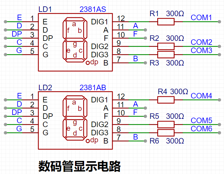
This project uses two 0.28-inch three-digit common-cathode LED displays as the display device. Compared to a display screen, LED displays offer better visibility in complex environments. The brightness of the LED displays can be increased by using smaller current-limiting resistors, depending on the specific needs of the application environment. Furthermore, LED displays have better mechanical properties and are not as easily damaged by external forces as display screens. They are widely used in industrial applications where stability and reliability are crucial. From a development board learning perspective, this makes it easier to learn electronic measurement principles and related development in a targeted manner.
In this project, actual testing showed that the current-limiting resistors (R1~R6) for the LED displays were configured to 300Ω. The corresponding brightness for both red and blue LED displays was good and the brightness was soft and not glaring.
Strictly speaking, the current-limiting resistors should be added to the segments; adding them to the digits would affect the display effect. Our actual design places them in the digits to save a few resistors, but the impact on the display is not significant. Therefore, we add them to the digits for convenience.
The
driving principle of LED displays mainly involves controlling the switching state of each segment of the LED display to display numbers, letters, or symbols. The following is a detailed explanation of the driving principle:
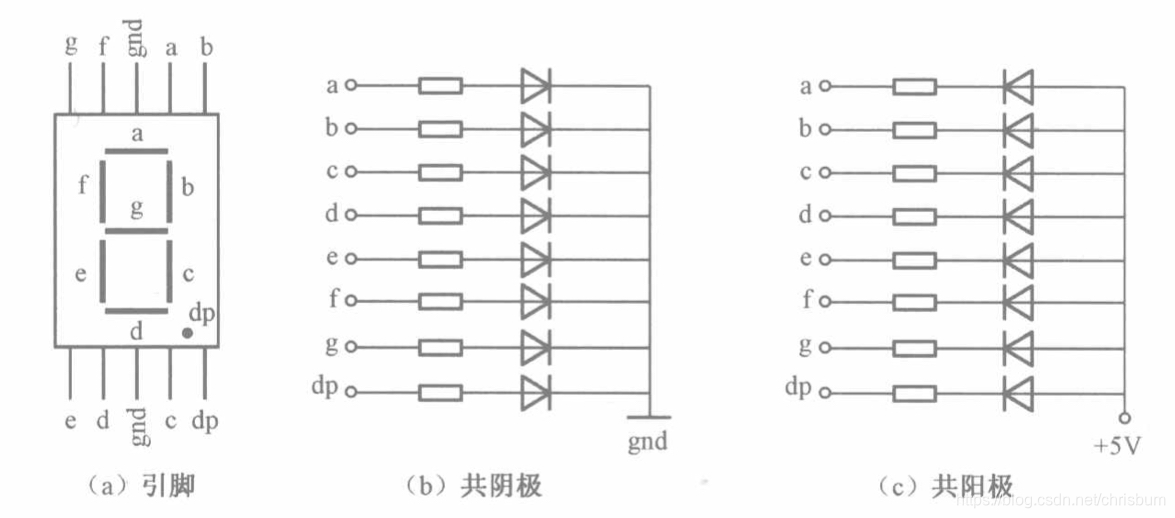
Basic Structure of a Digital Tube:
A digital tube typically consists of seven or eight LED segments (eight segments in this project). Each segment represents a part of the digital tube and can display numbers 0-9, letters AF, etc.
Digital tubes come in two types: common cathode and common anode. The difference lies in whether the common terminal COM (the end connecting all LEDs) is connected to the negative or positive terminal of the power supply.
Driving Methods:
Segment Selection: The desired number or character is displayed by controlling the on/off state of each segment of the digital tube. Each segment corresponds to a control signal; when the control signal is on, the segment lights up, and vice versa. (a, b, c, d, e, f, g, dp)
Bit Selection: The digital tube to be displayed is selected by controlling the bit lines of the digital tube. Bit line control sets the bit line of the digital tube to be displayed to a high level, and the bit lines of other digital tubes to a low level. By continuously switching the state of the bit lines, the display switching between multiple digital tubes can be achieved.
Driving Circuit:
The driving circuit for a digital tube can be implemented using hardware circuits, such as integrated circuits like digital signal processors (DSPs), microcontrollers (MCUs), or shift registers, to generate control signals suitable for the LEDs.
These control signals can be in the form of pulse width modulation (PWM) signals, serial data signals, etc. By controlling the frequency, width, and amplitude of these signals, the brightness of the digital tube can be controlled, thereby displaying the desired numbers or letters.
Software Control:
In addition to hardware driving circuits, the driving of digital tubes can also be implemented through software control. By programming to generate control signals suitable for the digital tubes, more flexible and complex display effects can be achieved, such as scrolling or alternating display of numbers.
Driving Common Cathode and Common Anode Digital Tubes:
For common cathode digital tubes, the common cathode pin is connected to the negative terminal of the power supply, and the control pin is connected to the output pin of the control chip. When a certain number needs to be displayed, the control chip outputs the corresponding encoded signal to the control pin, causing the corresponding LED segment to light up.
For common anode digital tubes, the working principle is similar to that of common cathode digital tubes, except that the common anode pin is connected to the positive terminal of the power supply, and the control pin is connected to the output pin of the control chip.
Encoded Display:
In order for the digital tube to display the corresponding numbers or characters, the segment data port must output the corresponding character encoding. For example, to display the number "0", the character code for a common anode seven-segment display is 11000000B (i.e., C0H), while the character code for a common cathode seven-segment display is 00111111B (i.e., 3FH). The specific code depends on the actual seven-segment display.
Dynamic and Static Display:
Seven-segment displays can use either static or dynamic display methods. In static display, each of the eight segments of each seven-segment display is connected to an 8-bit I/O port address. As long as the I/O port outputs a segment code, the corresponding character is displayed and remains unchanged. Dynamic display, on the other hand, lights up each segment of the seven-segment display one by one, achieving simultaneous visual display through rapid switching.
In summary, the driving principle of seven-segment displays is to control the switching state of each segment of the seven-segment display to display numbers, letters, or symbols, and to achieve display switching between multiple seven-segment displays through segment selection and digit selection. Furthermore, the driving of seven-segment displays can be implemented through hardware circuits or software control, and common cathode or common anode seven-segment displays can be selected as needed.
This project actually uses dynamic scanning display to drive the seven-segment display.
Calculate the required current for the digital tube.
This project actually uses dynamic scanning to drive the digital tube, so at any given time, only a maximum of 8 segments of the digital tube (or LEDs) can be lit, or in other words, only one digit can be lit. According to the design, the required driving current is approximately 11mA (3.3V ÷ 300Ω ≈ 11mA).
At this point, it's important to ensure that the selected MCU has sufficient current sinking/pulling capability.
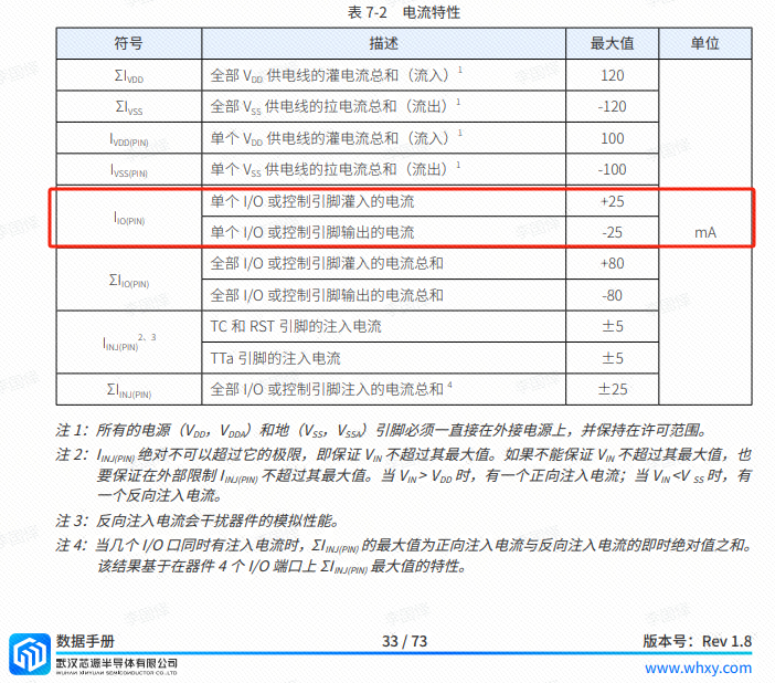
Analysis of the datasheet shows that CW32 is fine. (Some chips are not suitable.)
6. LED Indicator Lights
This project additionally designed a power indicator light and an IO operation indicator light.
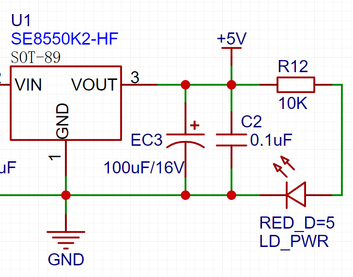
LD_PWR is the power operation indicator light .

Since chip I/O often has a greater current sinking capability than current pulling capability, LED1 is designed to be active low (on).
To reduce the current consumption of the LEDs, some LED brightness is sacrificed, the component parameter types are reduced, and the LED current-limiting resistor is selected as 10K.
7. Button Circuit Design

There are multiple design options for the button control circuit. Thanks to the CW32's internal I/O ports which can be configured with pull-up and pull-down resistors, the button control circuit on the chip's periphery does not require configuration. One end of the button is connected to the MCU's I/O, and the other end is grounded. When the button is pressed, the I/O is pulled low.
8. TL431 Circuit Design for Voltage Measurement and Calibration:
This project adds an extra TL431 circuit to provide a 2.5V reference voltage, which can be used to provide an external voltage reference for calibrating the AD converter. From a product design perspective, due to the CW32's inherent ADC performance advantages, this circuit is not necessary. This circuit is designed on the development board for learning related application principles.

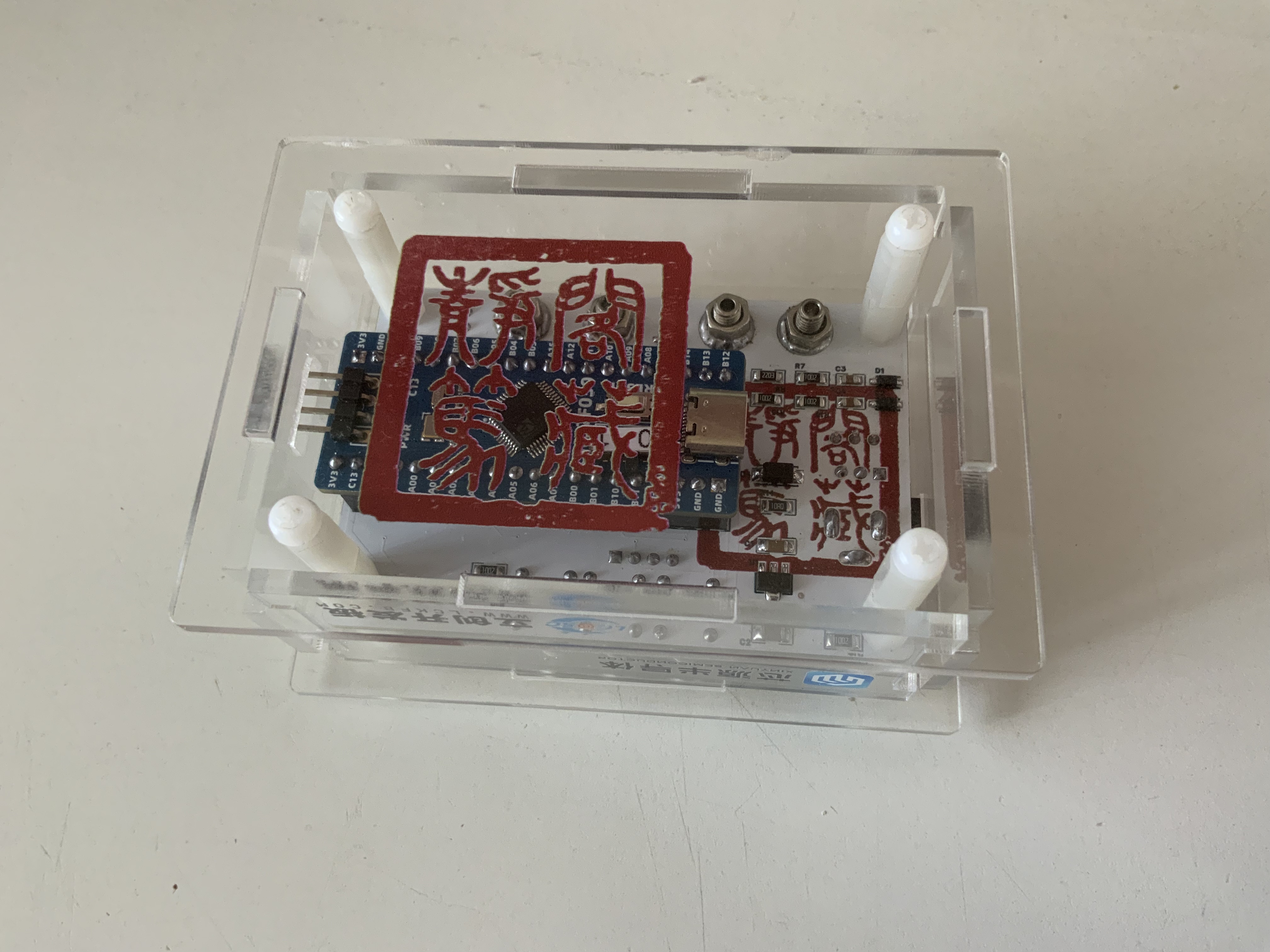
III. Product Diagram and Brief Introduction:
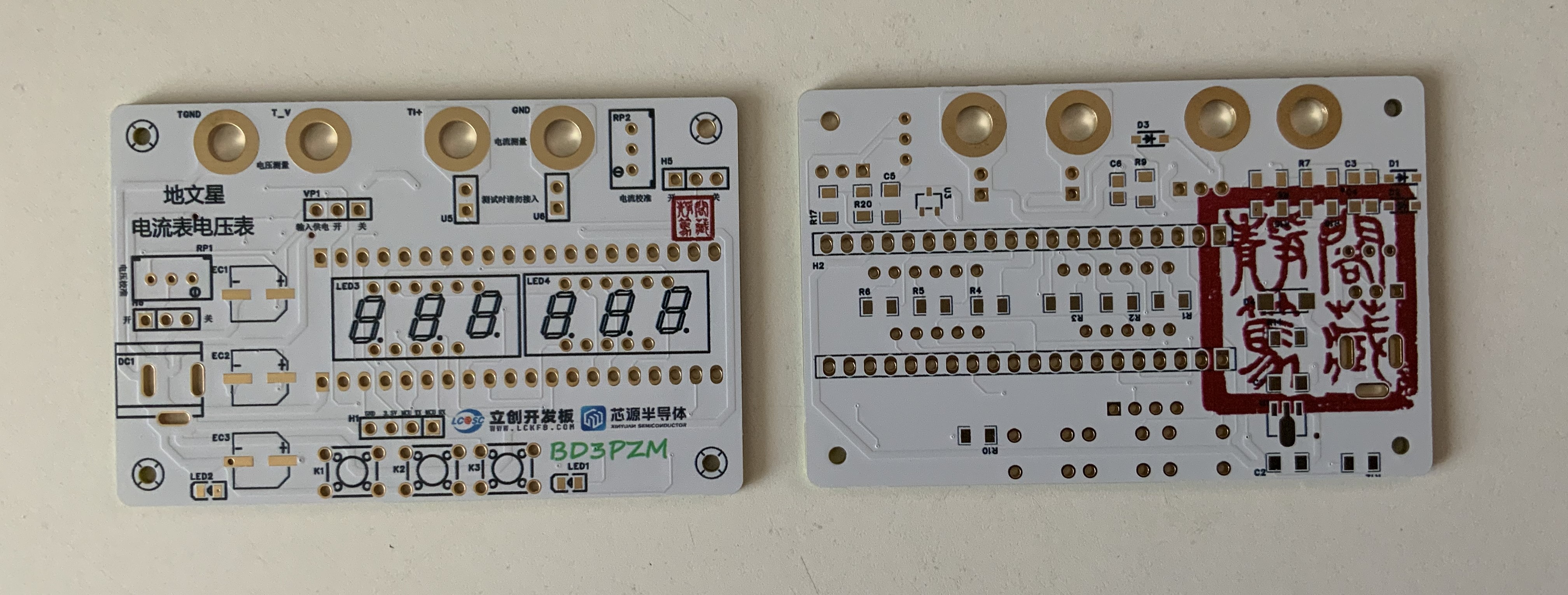
Thanks to JLCPCB's monthly freebie program, five boards were made at once. I must say, JLCPCB's immersion gold and color silkscreen printing processes are truly beautiful.
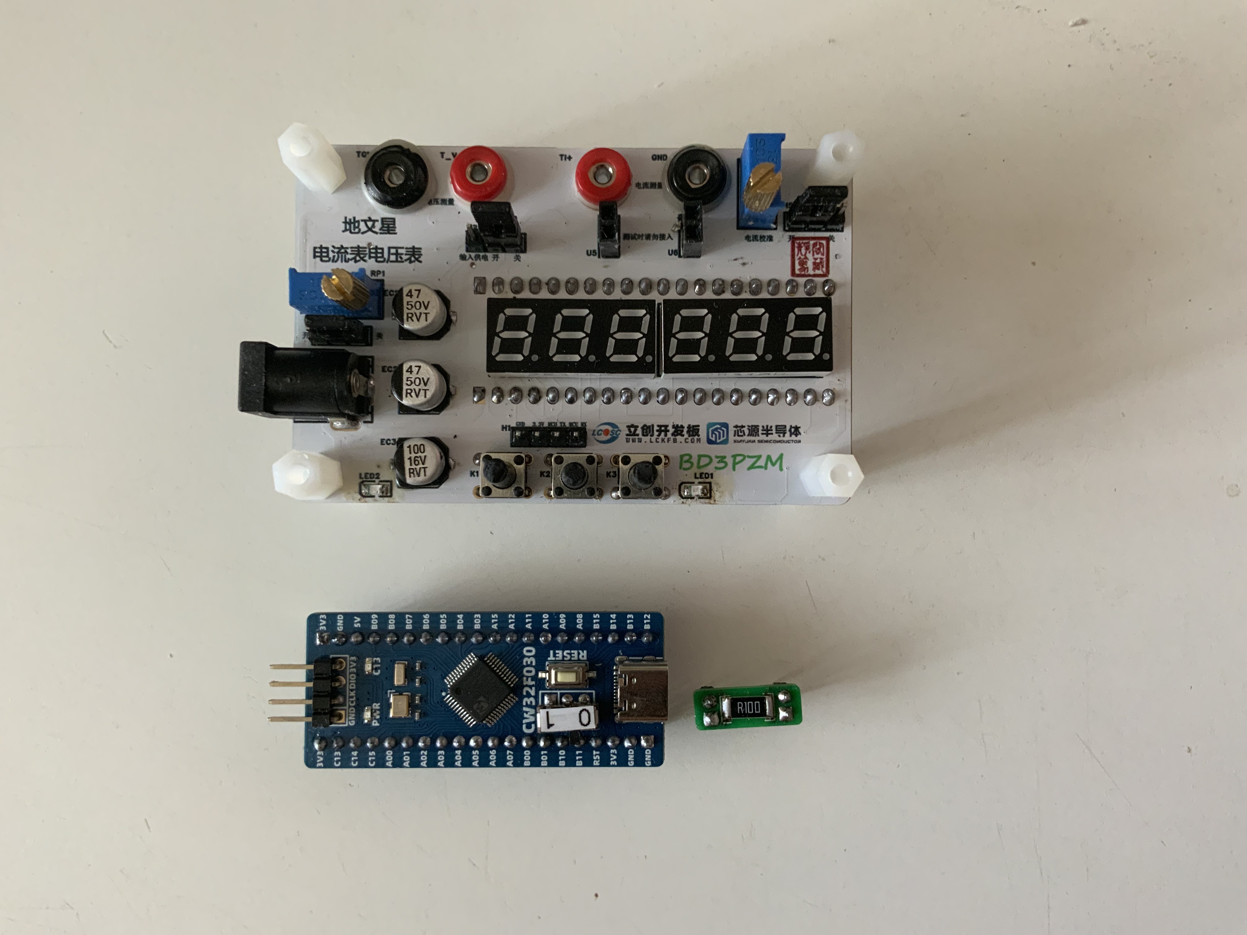
This is what it looks like after soldering the components. I changed the jumpers on the CW32 development board to single-pole double-throw switches
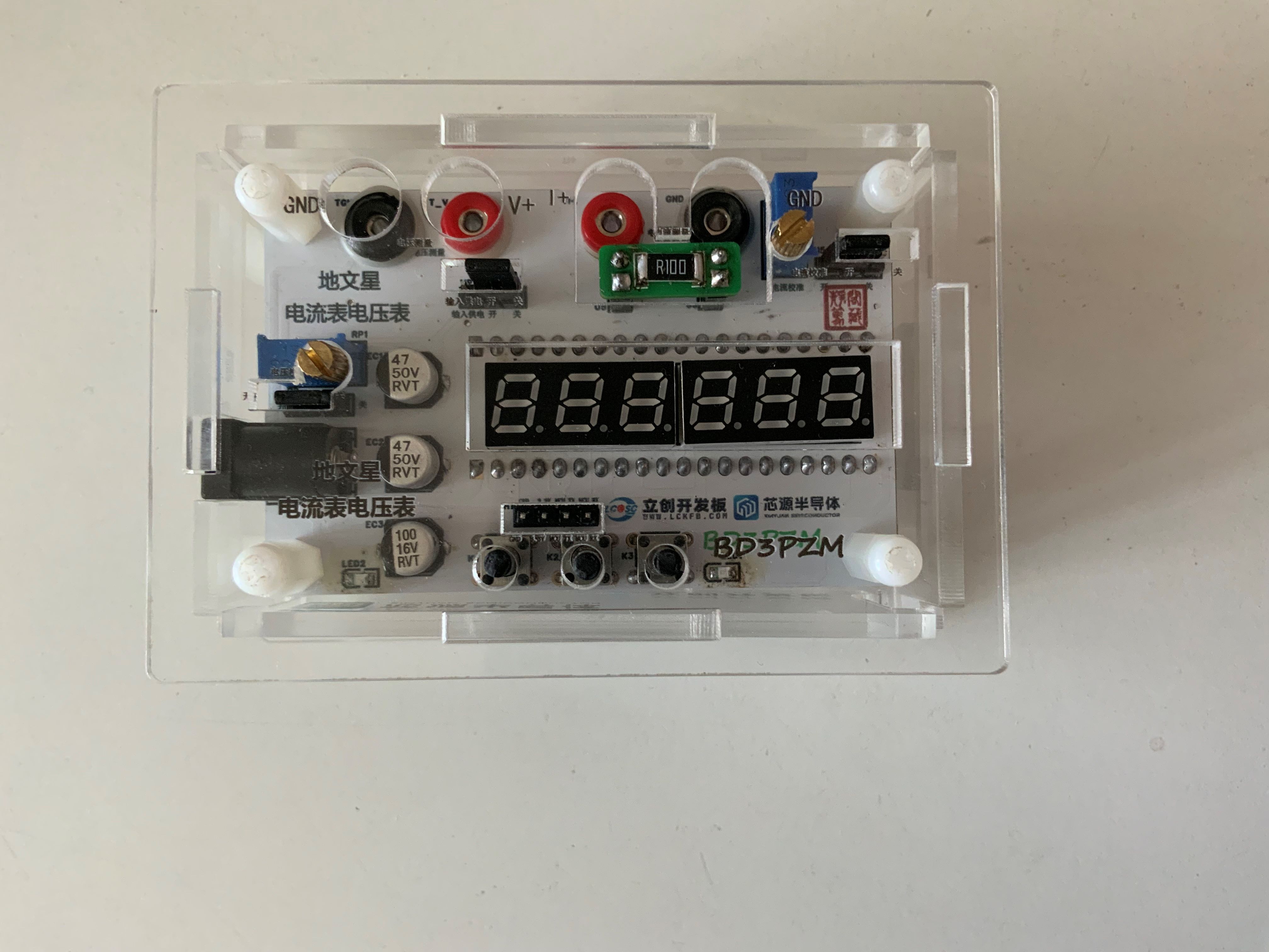
. This is what it looks like after installing the casing. Due to my lack of experience in designing boards for the first time, the long side of the vertical panel is 6mm shorter. The diagrams in the open-source file have been modified. The acrylic casing for the digital display has a windowed design to reduce glare. This window can be removed if aesthetics and a more cohesive look are desired.
Finally, I would like to thank LCSC Development Board and Sinyuan Semiconductor for organizing this training camp, which allowed me to systematically learn about PCB design and development boards.


 京公网安备 11010802033920号

 05WS36


