Project Introduction:
As an electronics enthusiast, designing and building a voltmeter and ammeter is a valuable opportunity for in-depth learning and practice of basic circuit components, microcontrollers, and programming, helping to improve and solidify one's fundamental knowledge and skills.
First, let's look at the actual product. This is a voltmeter and ammeter based on the LCSC CW32F030C8Tx development board. It has basic voltage and current measurement functions, and also features voltage range measurement, simulated voltage and current measurement, voltage calibration, and voltage calibration circuitry, which helps in understanding the voltage and current measurement and calibration process.
The entire board uses only one surface-mount component; the rest are through-hole components, greatly reducing the soldering difficulty and making it ideal for practice.

LCSC CW32F030C8Tx Development Board (Core Board)

Key Advantages of CW32 in this Project
: Wide operating temperature range: -40~105℃;
Wide operating voltage: 1.65V~5.5V (STM32 only supports 3.3V systems)
; Strong anti-interference: HBM ESD 8KV; All ESD reliability reaches the highest international standard level (STM32 ESD 2KV);
Project Focus - Better ADC: 12-bit high-speed ADC, achieving ±1.0LSB INL 11.3ENOB; Multiple Vref reference voltages... (STM32 only supports VDD=Vref);
Stable and reliable eFLASH technology.
Knowledge Summary:
Through this project, you can learn the following:
The basic principle of voltage and current measurement using resistor voltage dividers;
Component selection and design of power supply modules;
Application of multi-digit LED modules;
Using average filtering methods to improve the stability of sampling result display;
Using calibration methods to further improve sampling accuracy.
Special Features
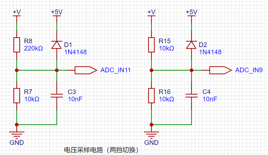
: 1. Switchable Voltage Sampling Circuit:
This project uses a 220K+10K voltage divider resistor, resulting in a voltage division ratio of 22:1 (ADC_IN11).
To improve voltage measurement accuracy, a switching function is specifically designed. Implementing this function requires a combination of hardware and software. When first using the ADC_IN11 channel to measure voltages below 30V, if the measured voltage is within 0~3V, then use the ADC_IN9 channel for measurement. At this time, due to the reduced voltage division ratio, the measurement accuracy is greatly improved.
2. Current Sampling Circuit:
This project uses a low-side current sampling circuit for current detection. When learning the common ground between the low-side of the sampling circuit and the development board's meter interface, please do not solder R0!

3. TL431 Circuit Design for Voltage Measurement Calibration:
This project adds an additional TL431 circuit to provide a 2.5V reference voltage. This can be used to provide an external voltage reference for calibrating the AD converter. From a product design perspective, due to the inherent ADC performance advantages of the CW32, this circuit is not necessary. Design this circuit on a development board to learn related application principles.

The design analysis shows
that the sampling current in this project is 3A, and the selected sampling resistor (R0) is 100mΩ. The selection of the sampling resistor mainly needs to consider the following aspects:
the maximum value of the pre-designed measurement current;
the voltage difference caused by the 3A current sensing resistor in this project; generally, it is not recommended to exceed 0.5V
; the power consumption of the current sensing resistor should be selected based on this parameter. Considering the power consumption (temperature) issue under high current, a 1W metal wire-wound resistor was selected in this project;
the voltage amplification factor of the current sensing resistor: no operational amplifier is used to build the amplification circuit in this project, so the factor is 1.
Then, the current sensing resistor value can be calculated using the above parameters.
Since this project... Since no amplifier circuit is used, a larger sampling resistor is needed to obtain a higher measured voltage for measurement.
Considering that a larger resistor would result in a larger voltage drop and higher power consumption, an unlimited selection of a larger resistor is not feasible.
This project uses a 1W package resistor, corresponding to a temperature rise power of 1W.
Based on the above data, a 100mΩ current sensing resistor was selected. According to the formula, 3A * 100mΩ = 300mV, 900mW can be calculated.
To cope with different operating environments, especially high current scenarios, the R0 resistor can be replaced with constantan wire or a shunt. The replacement can be selected according to the actual application scenario. For safety and educational purposes, this project will not discuss measurements exceeding 3A, but the principle is the same.
4. Measurement Calibration
Definition: Five working modes are defined. The K1 key is used to switch the display mode. The K2 key sets the parameter value for the corresponding mode and saves it to FLASH. The K3 key returns to mode 0.
Mode 0: Displays normal voltage and current values (the upper row of digital tubes displays the voltage value *.V or .*V automatically, the lower row displays the current value _.**A).
Mode 1: 5V voltage calibration setting. The upper row of digital tubes displays 5.05. The lower row displays the current voltage value _.V or ._V. In this mode, the multimeter should be set to 5.00V when measuring the measured bit. Pressing the K2 key will calibrate the current value to 5V.
Mode 2: 15V voltage calibration setting. The upper row of digital tubes displays 5.15. The lower row displays the current voltage value _.V or ._V. In this mode, the multimeter should be set to 15.0V when measuring the measured bit. Pressing the K2 key will calibrate the current value to 15V.
Mode 3: 0.5A current calibration setting. The upper row of digital tubes displays A.0.5. The lower row displays the current current value _.**A. After pressing the K2 key, the current value is calibrated to a 0.5A current value.
Mode 4: Current 1.5A calibration value setting. The upper row of the digital tube displays A.1.5. The lower row displays the current current value *.**A. After pressing the K2 key, the current value is calibrated to a 1.5A current value.
The measurement progress is improved after calibration, as shown below, with an error range within 0.03.

5. Simulated Voltage and Current Measurement
This project can realize the simulated measurement of voltage and current. This function can also be used for the calibration of voltage and current measurements. Shorting JP1 can perform simulated voltage measurement, and shorting JP2 can perform simulated current measurement. See the video for details.


 京公网安备 11010802033920号

 121642R-12X778


