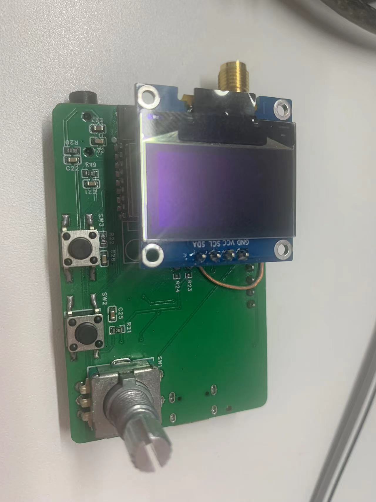
Open-source firmware for an FM radio implemented using ESP32C3 and RDA5807 chips: https://github.com/zzyandzzy/esp32c3-fm (Image of the actual device follows)
PDF_FM Radio.zip
Altium_FM Radio.zip
PADS_FM Radio.zip
BOM_FM Radio.xlsx
93157
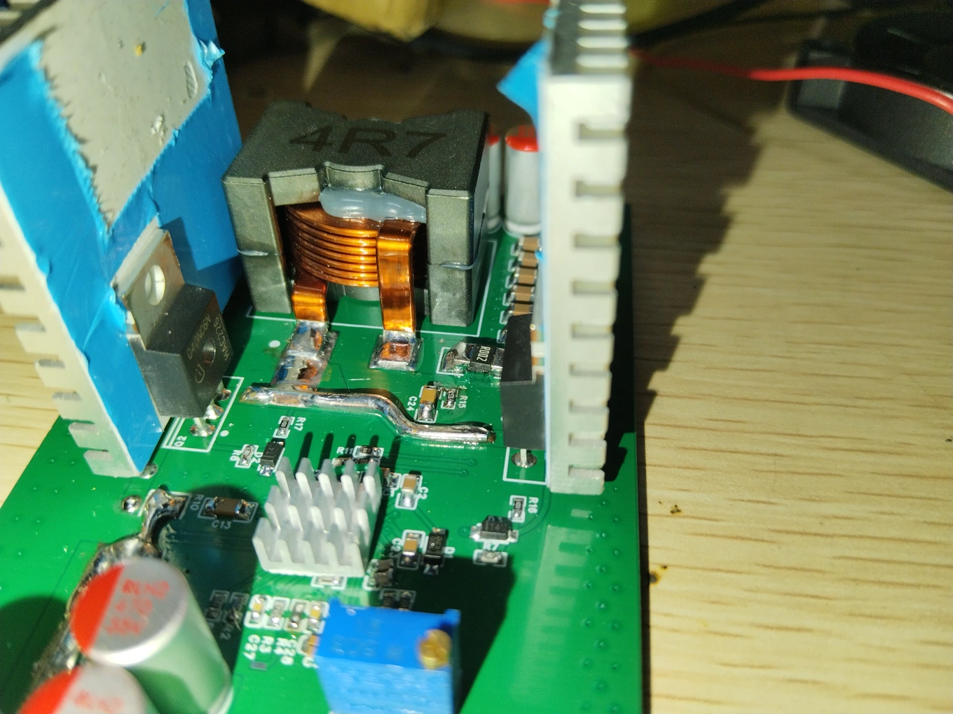
SC8201 High-Power Synchronous Boost Module
The boost module, which uses the SC8201 synchronous boost chip, was originally intended to power laptops.
I. Initial Intent:
The school dormitory cuts off the power every night at 11 pm, and sometimes I need to run some demanding applications on my laptop. It's not ideal to always use the laptop battery. I happened to have a 12V lead-acid battery on hand, so I wanted to use a high-efficiency boost module to utilize this battery to power my laptop. Since I couldn't find a satisfactory one on Taobao (or they were too expensive), I ended up tinkering (
which involved researching, buying a bunch of tools and components, and then realizing the total cost had far exceeded my expectations).
II. Design Summary
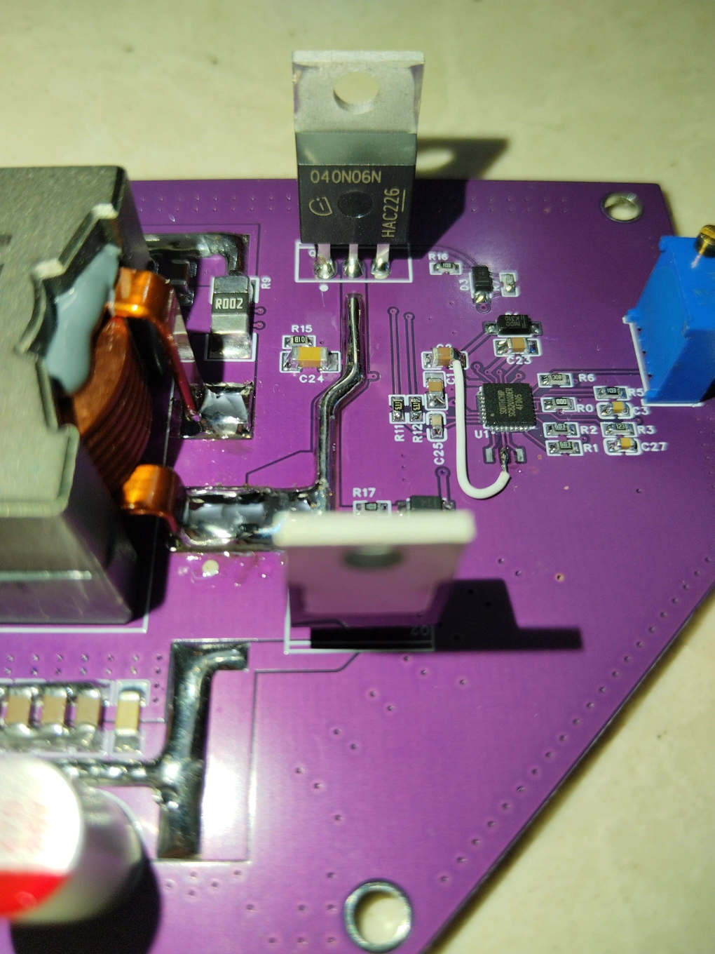
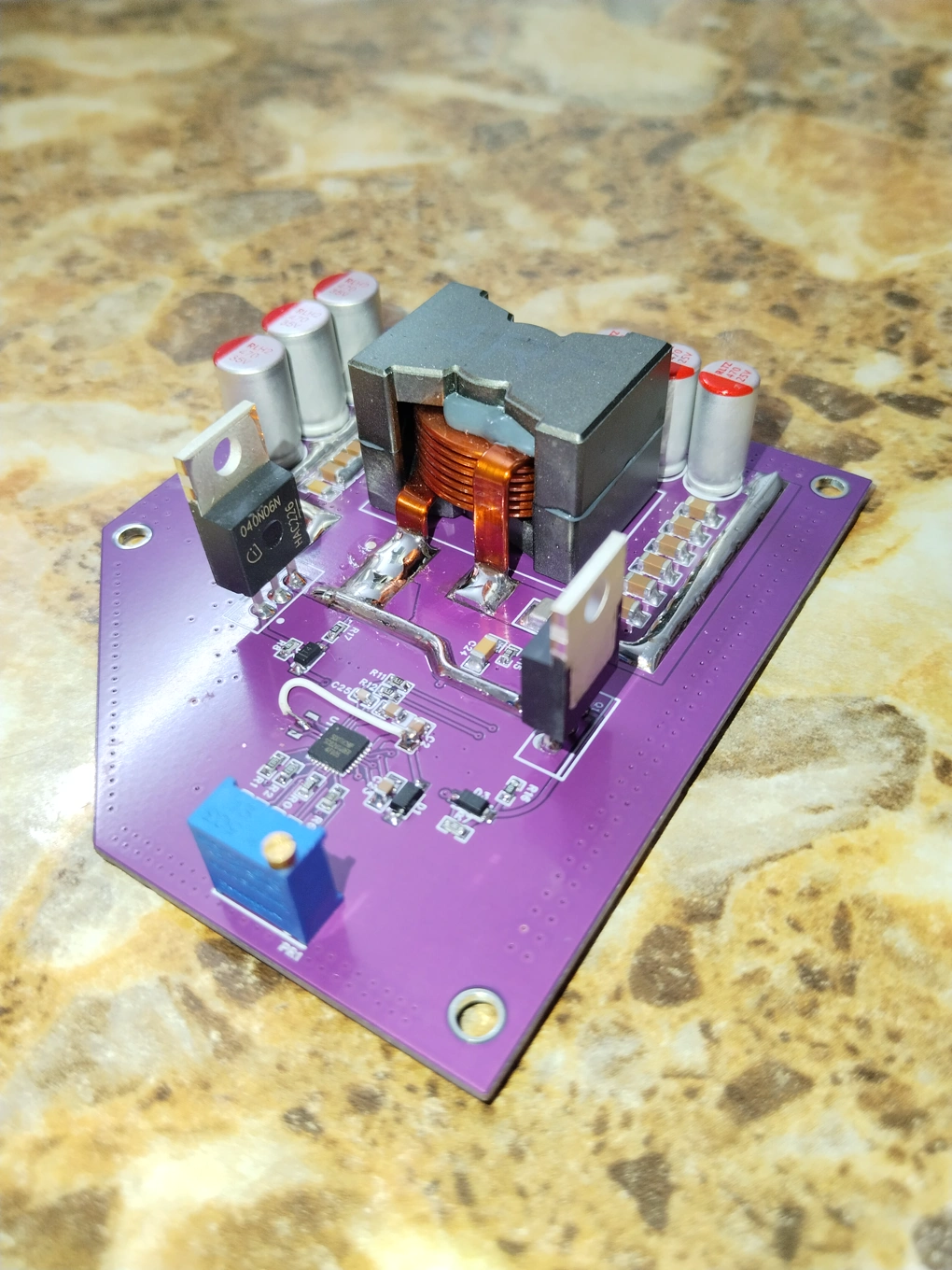
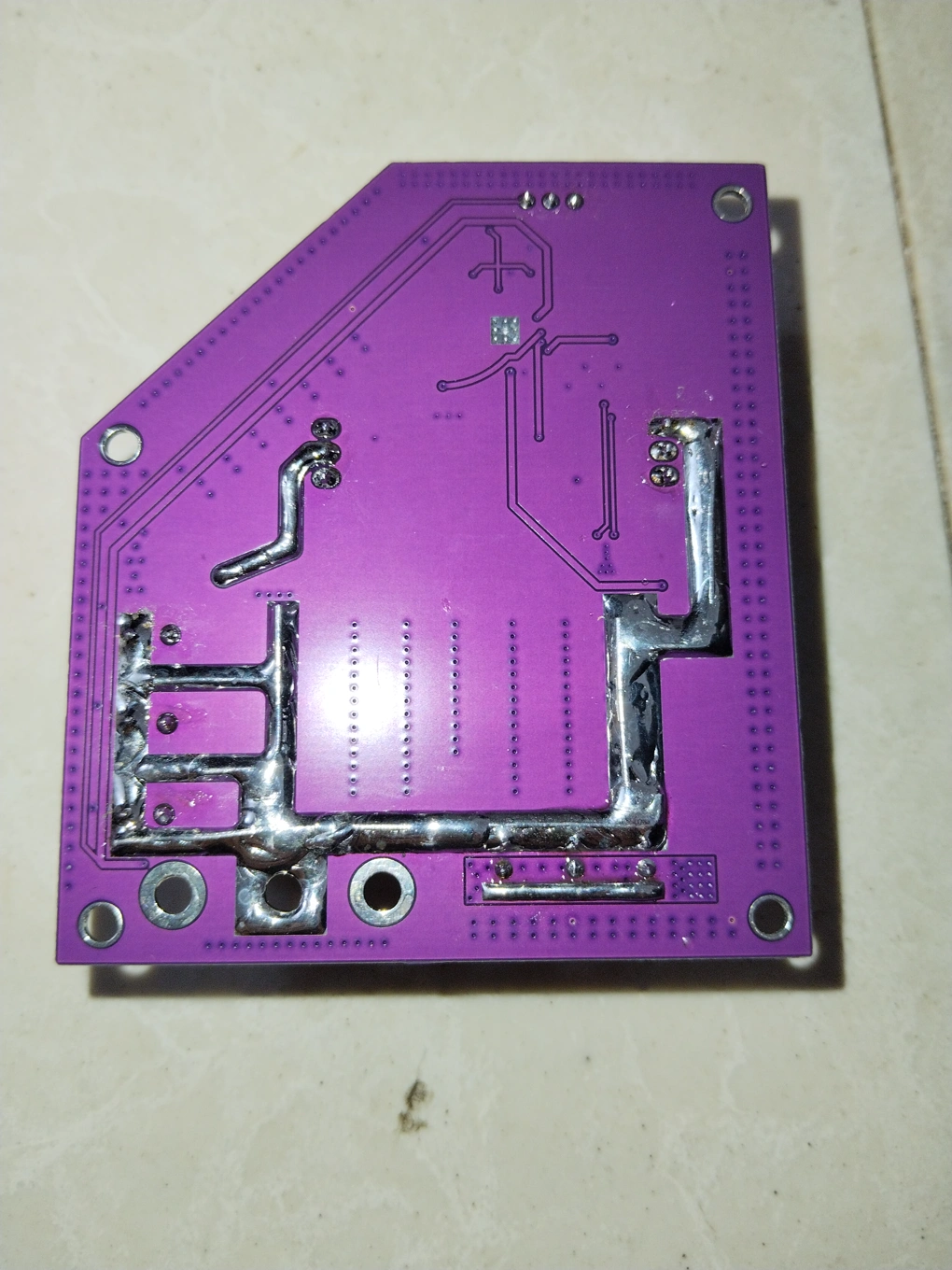
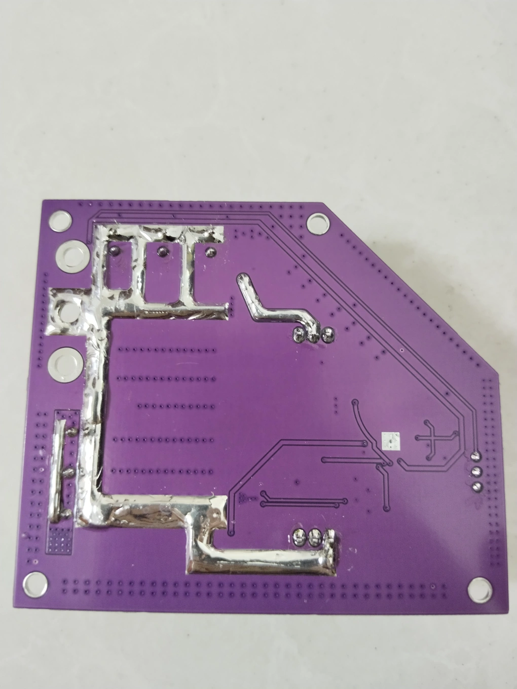
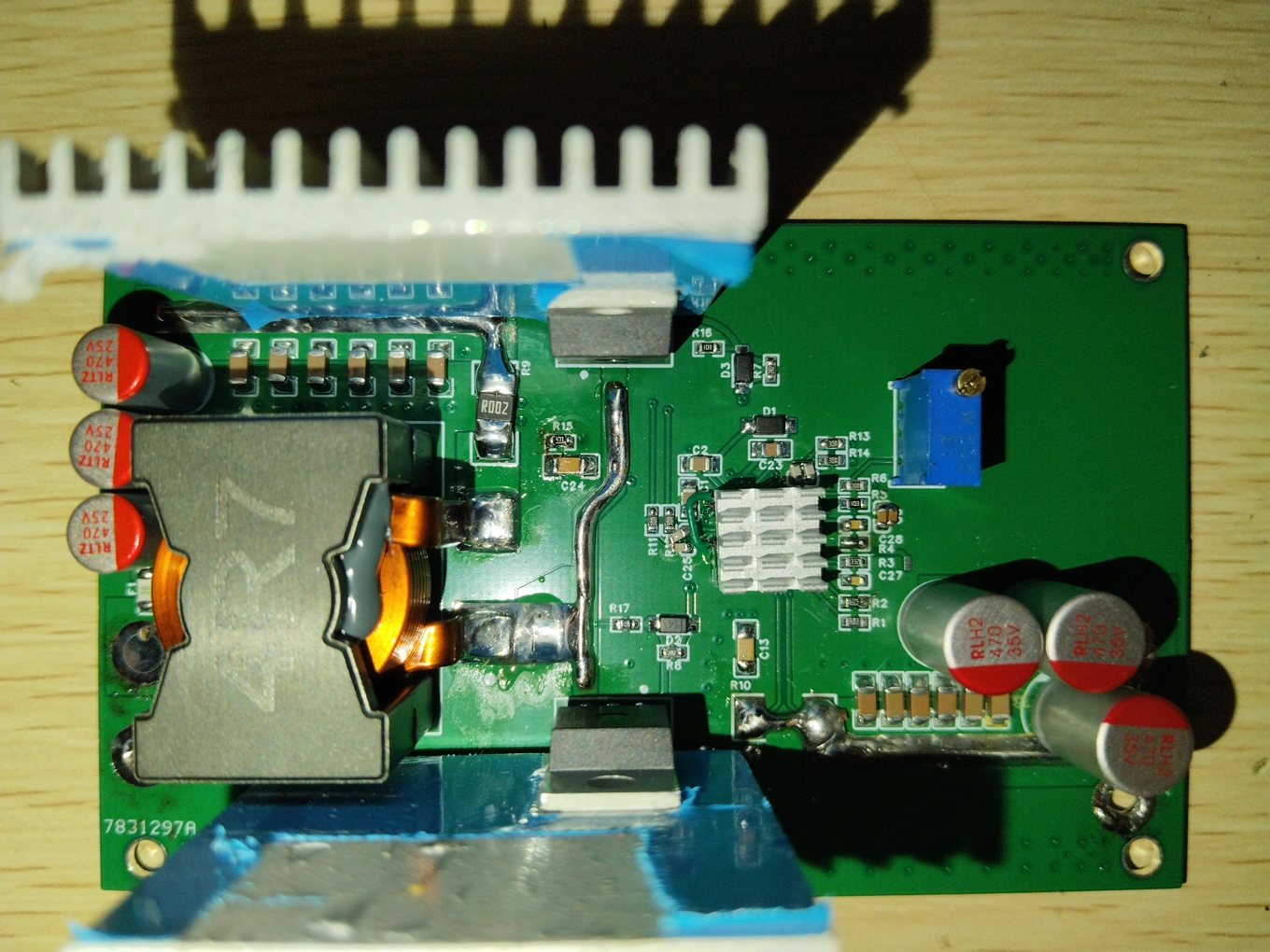
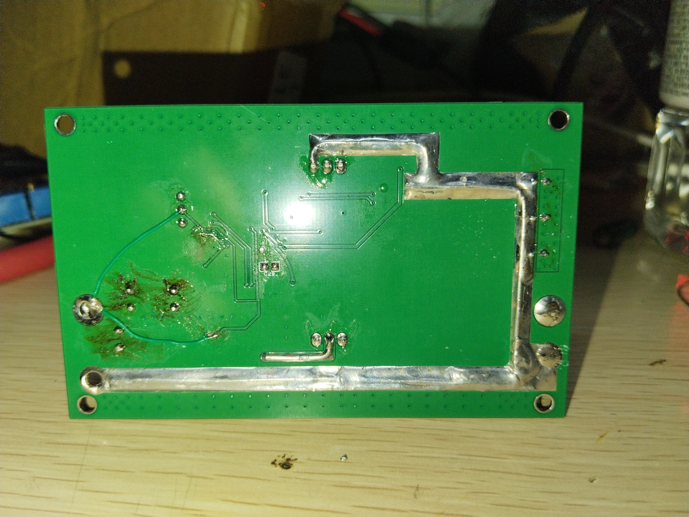
: After consideration, the final boost controller used was the Southchip SC8201, and the power transistors were TO-220 packaged IPP040N06N. High-current traces on the PCB were soldered or buried copper. The power transistor routing followed the SC880x/SC870x routing guidelines. Component parameters are detailed in the SC8201 documentation and engineering circuit diagram.
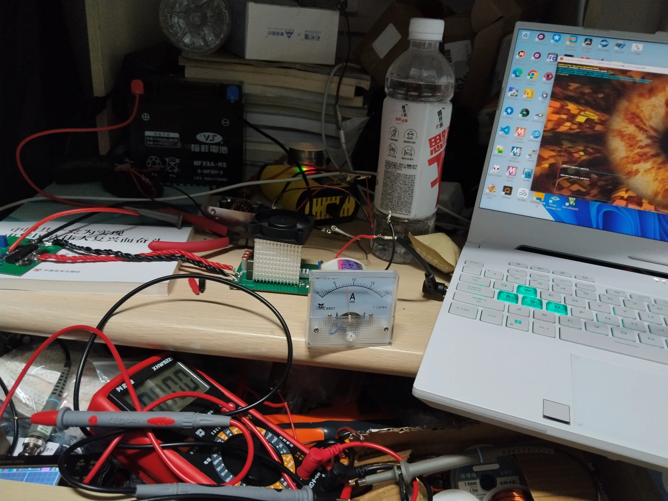
III. Physical Images & Test Diagrams:
New Generation Finished Product Physical Images & Test Diagrams
: Physical Images:

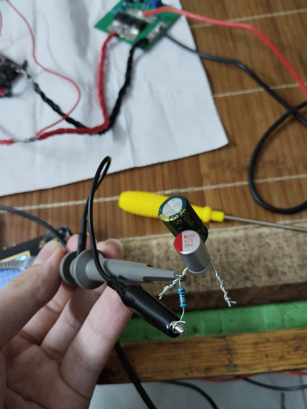
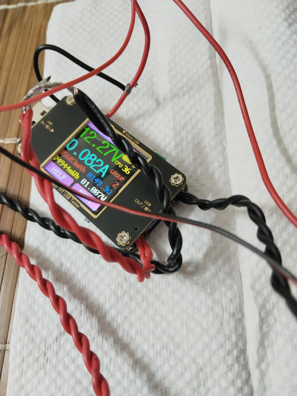
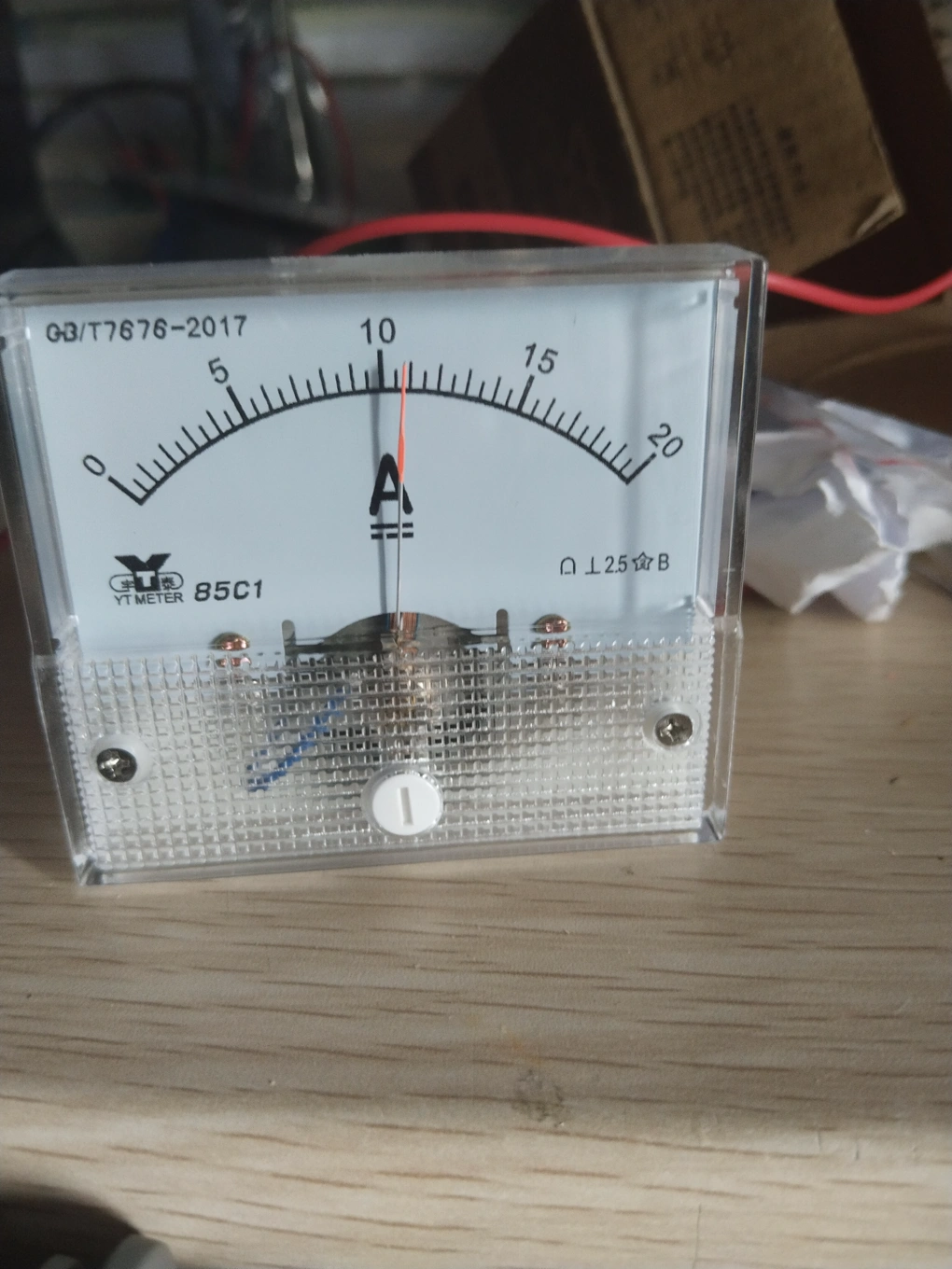
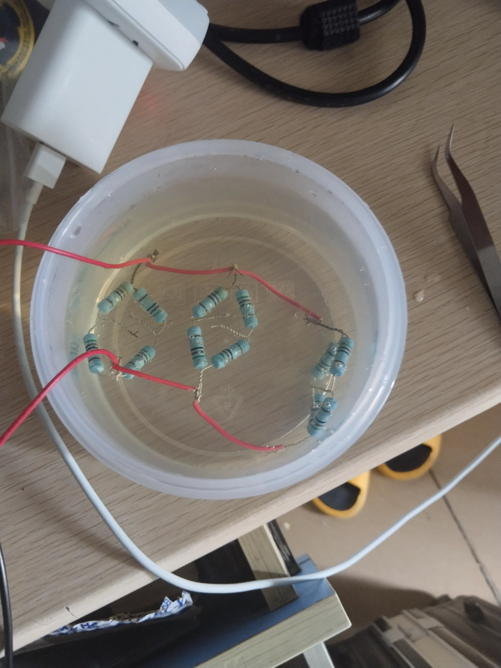
Test:
For ripple measurement, since my small oscilloscope doesn't seem to have a direct ripple measurement function, I used two capacitors and a 10-ohm resistor to help measure the ripple. I'm not sure how accurate it is.
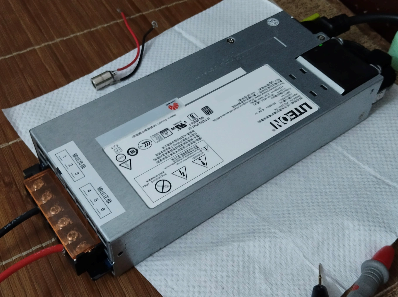
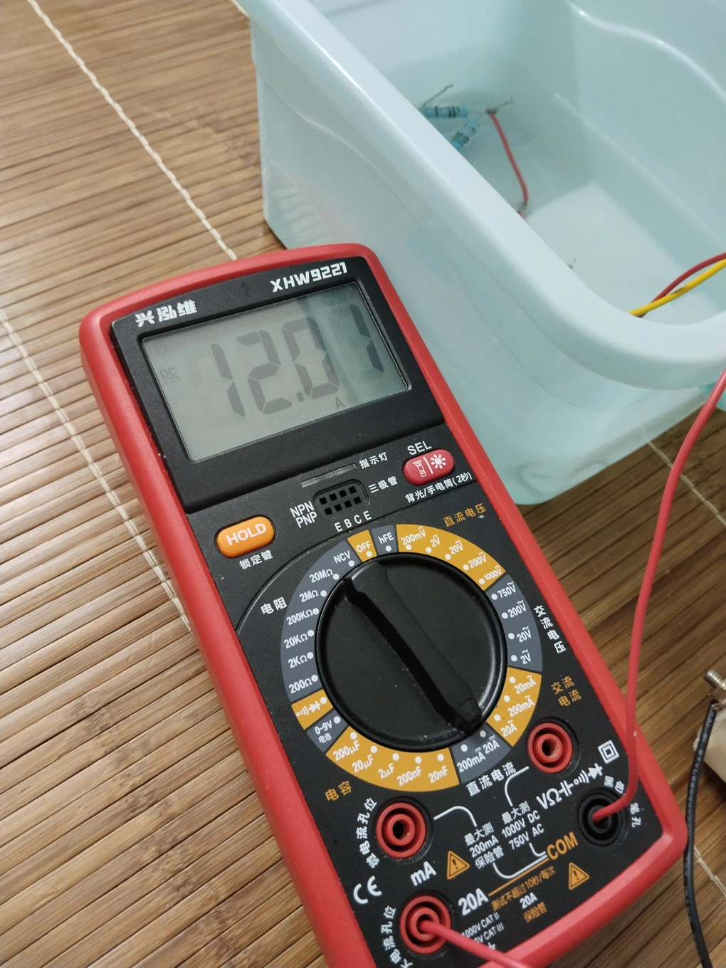
12V power supply:
Output 20V:

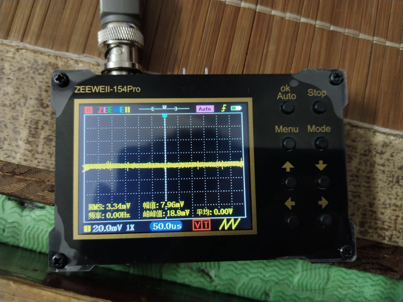
No-load ripple:
No-load power consumption:
With a 1.7 ohm dummy load resistor, output current 12A, input current 21.2A (due to the long wire, the input voltage dropped from 12.16V at the power supply output to 11.68V):

Ripple at this time:

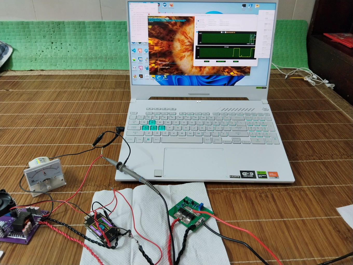
Powering a laptop, then dual-stress test:

Old version finished product picture & test picture
Output 20V, with 1.7 ohm resistor / laptop test

IV. Supplement
This project mainly references the following projects:
https://oshwhub.com/diy-lover1123/high-power-automatic-buck-boost-module-sc8701
https://oshwhub.com/aknice/sc8701
Due to limitations, not much testing was done. Roughly estimated efficiency can reach over 95%, but standby power consumption is a bit high, around 1W, but I personally feel it's not a big problem.
Some time before this project was released, I accidentally broke the double-layer PCB The original project was accidentally deleted, so what is being released now is the still-existing multilayer board project file.
I haven't been using JLCPCB EDA for very long, and the circuit diagram and PCB layout have been modified many times, resulting in some component numbering issues. Please forgive me.
PDF_SC8201 High Power Synchronous Boost Module.zip
Altium_SC8201 High Power Synchronous Boost Module.zip
PADS_SC8201 High Power Synchronous Boost Module.zip
BOM_SC8201 High-Power Synchronous Boost Module.xlsx
93158
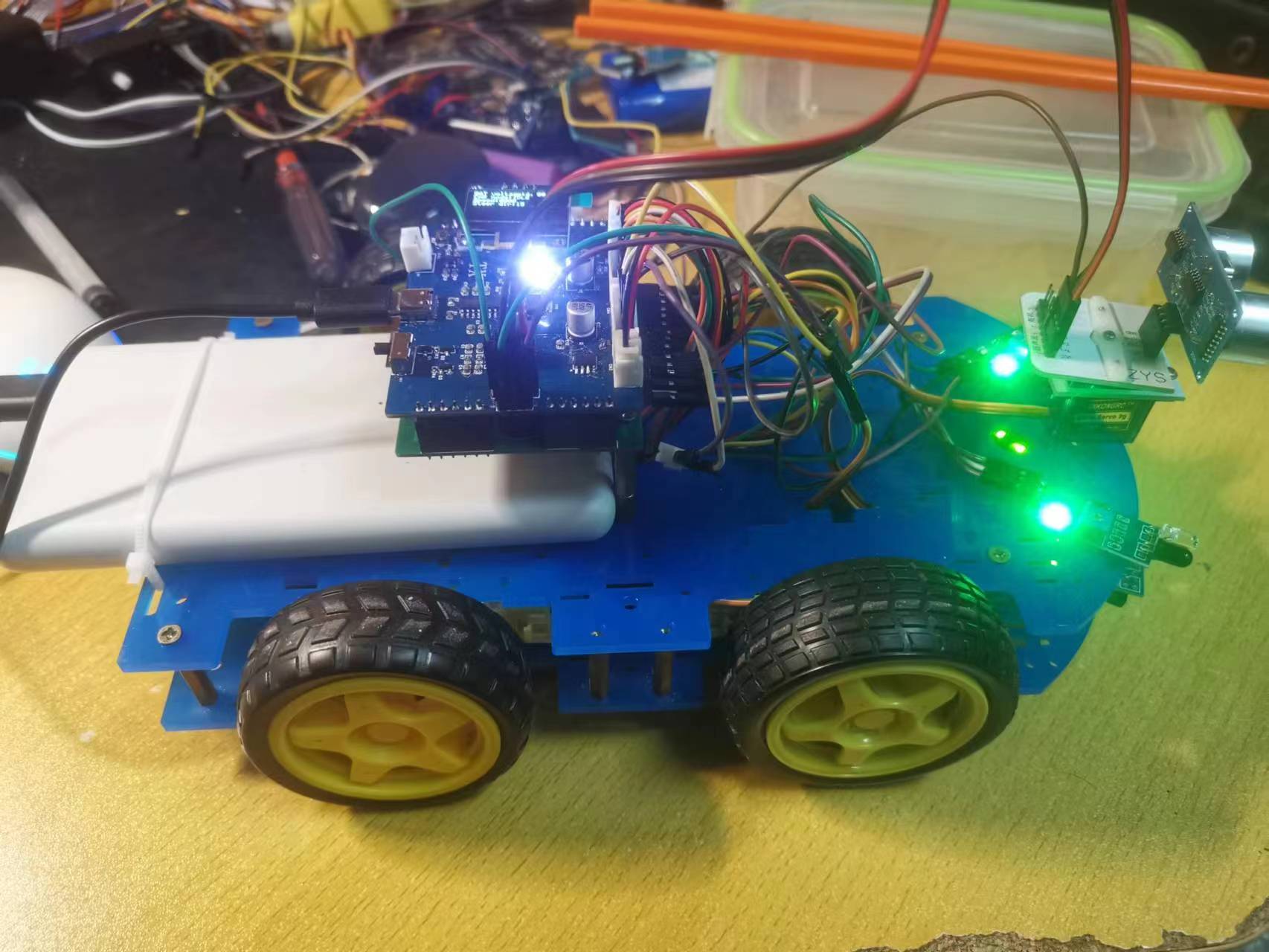
STM32 small car
This is an open-source project for a multi-functional car based on the STM32F103RCT6. The project includes the car's circuitry and code. It enables functions such as line tracking, obstacle avoidance, following, magic hand control, Bluetooth remote control, and debugging. The project code is open-sourced on Gitee.
This project introduces
a multi-functional car based on the STM32F103 microcontroller.
The project includes the car's circuitry and code.
Features include:
1. Infrared tracking and obstacle avoidance;
2. Ultrasonic following and hand-held control;
3. Bluetooth remote control (including car mode switching, motor speed switching, buzzer, and ultrasonic gimbal direction adjustment; detailed instructions can be found in the BLE_CMD.txt file within the project code);
4. Battery level monitoring;
5. Car running status display.
The project code is open-source on Gitee: https://gitee.com/huantianxiang/stm32-multifunctional-car
PS: The project still has several minor issues. The circuit design and code are for reference only. The author may erratically fix bugs; it is recommended to download the project code from Gitee.
Changelog:
1. The circuit error requiring a power bank in the demo video has been corrected; a new power switching circuit has been incorporated into the project.
2. A bug related to a mutex lock has been fixed.
Installation instructions:
Based on the PCB design, fabricate the PCB and solder the Bluetooth module (TB link: https://item.taobao.com/item.htm?spm=a1z09.2.0.0.58002e8dYwcRfT&id=680407598171&_u=t201f92g3ff119).
Connect the PCB using a Type-C cable and burn the HEX
file. Assemble the car according to the schematic diagram of the PCB design.
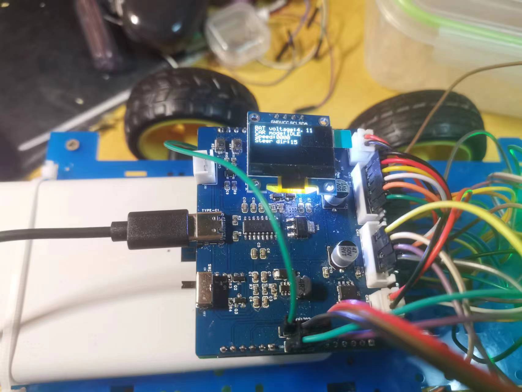
Instructions:
The Type-C port on the PCB is used for power supply and STM32 programming
. Commands sent via Bluetooth must end with "./", otherwise they will not be counted as commands
. The car's default speed is zero when it starts. If the car stops after switching modes, check the OLED screen to see if the speed is not zero. If it is zero, set the car speed via Bluetooth.
Car Tracking.mp4
Car following.mp4
Car obstacle avoidance.mp4
Little Car Magician.mp4
Remote control for a small car.mp4
Project code.zip
PDF_STM32 Car.zip
Altium_STM32 car.zip
PADS_STM32 Car.zip
BOM_STM32 Car.xlsx
93159
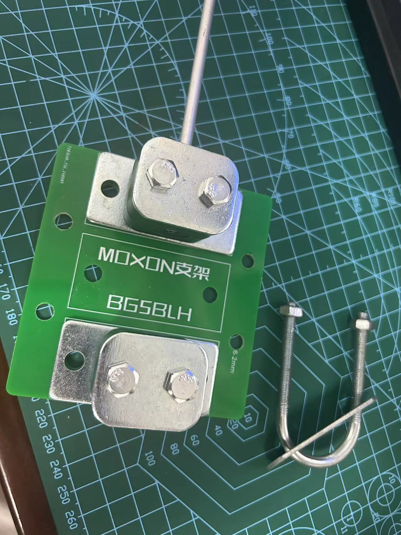
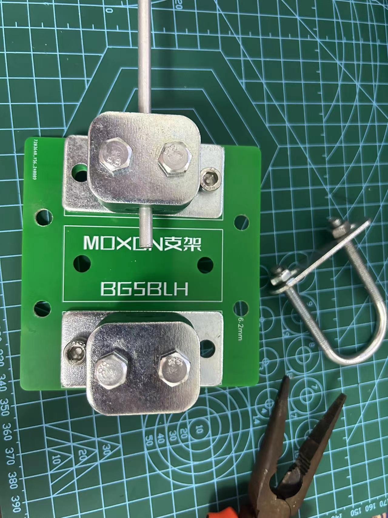
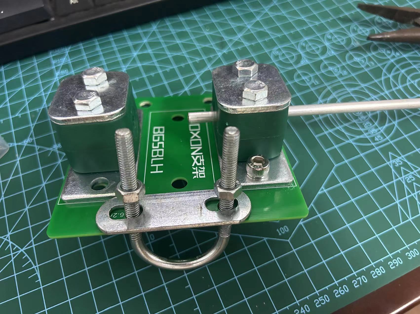
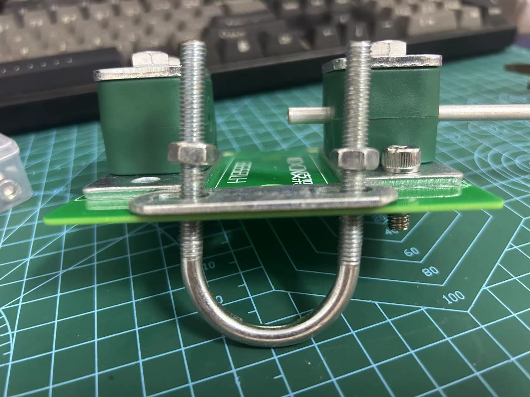
MOXON antenna bracket plate - amateur radio
MOXON antenna bracket plate - amateur radio
I calculated the dimensions of the MX1 coupling using a calculator.
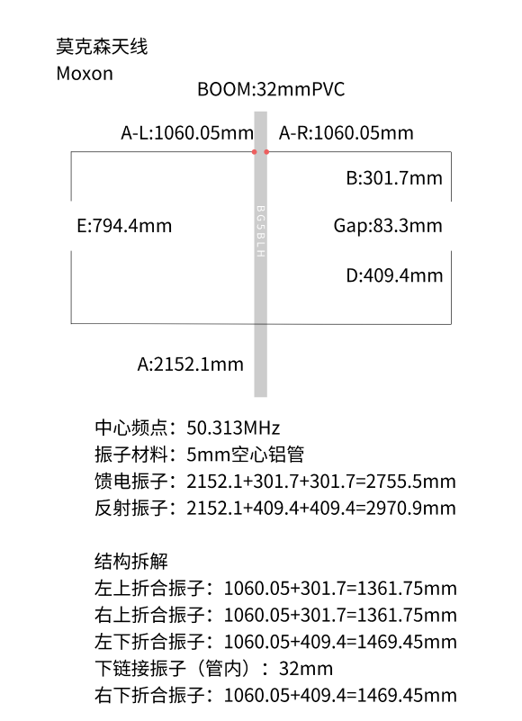
I had previously made a 2-meter MX1, but the 6-meter size is too large, and the coupling connection is a bit wobbly.

I plan to redo the coupling using oil pipe clamps for fixation.


PDF_MOXON Antenna Mount Plate - Amateur Radio.zip
Altium_MOXON Antenna Mount Plate - Amateur Radio.zip
PADS_MOXON Antenna Mount Plate - Amateur Radio.zip
BOM_MOXON Antenna Mount Plate - Amateur Radio.xlsx
93160
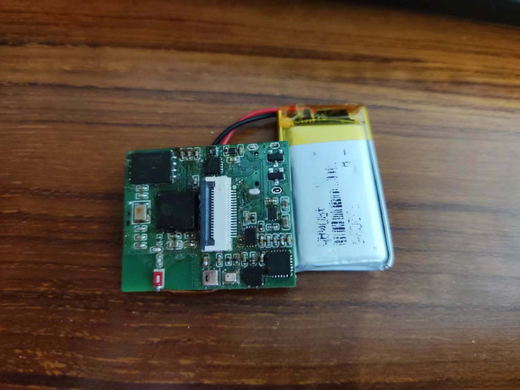
ESP32 watch
This smartwatch integrates environmental monitoring, visual touch control, battery management, and network communication functions. It uses an ESP32 microcontroller, a FreeRTOS operating system, an LVGL-developed GUI, and MQTT and HTTP protocols for network communication.
#ESP32 Smartwatch
#### Introduction This project aims to design a smartwatch integrating environmental monitoring, visual touch control, battery management, and network communication functions. The watch uses the ESP32S3 microcontroller as its core, FreeRTOS as its operating system, the LVGL embedded GUI framework for the user interface, and OneNET as its cloud platform for data access. Some circuit designs in this project are inspired by those of the renowned designer Qifan.
Project open-source address (the latest project updates are generally on Gitee, and all files can be found on Gitee): https://gitee.com/huantianxiang/esp32-watch

#### Watch Functionality Demo video in Pics/show.mp4
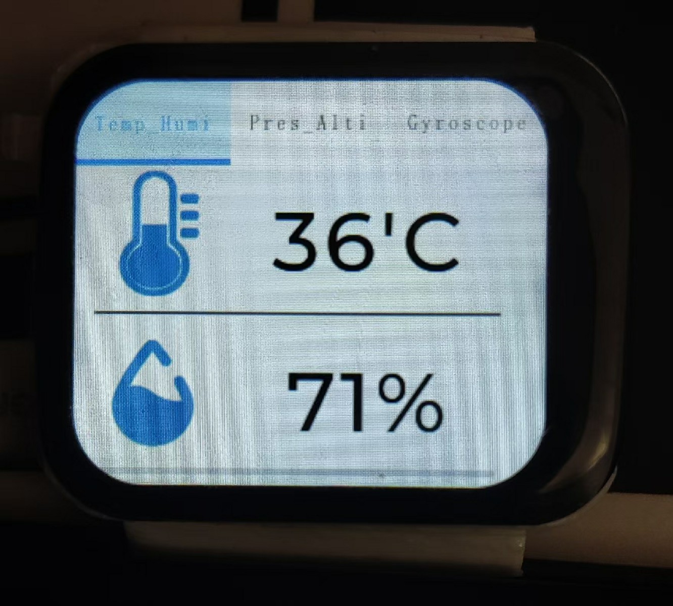
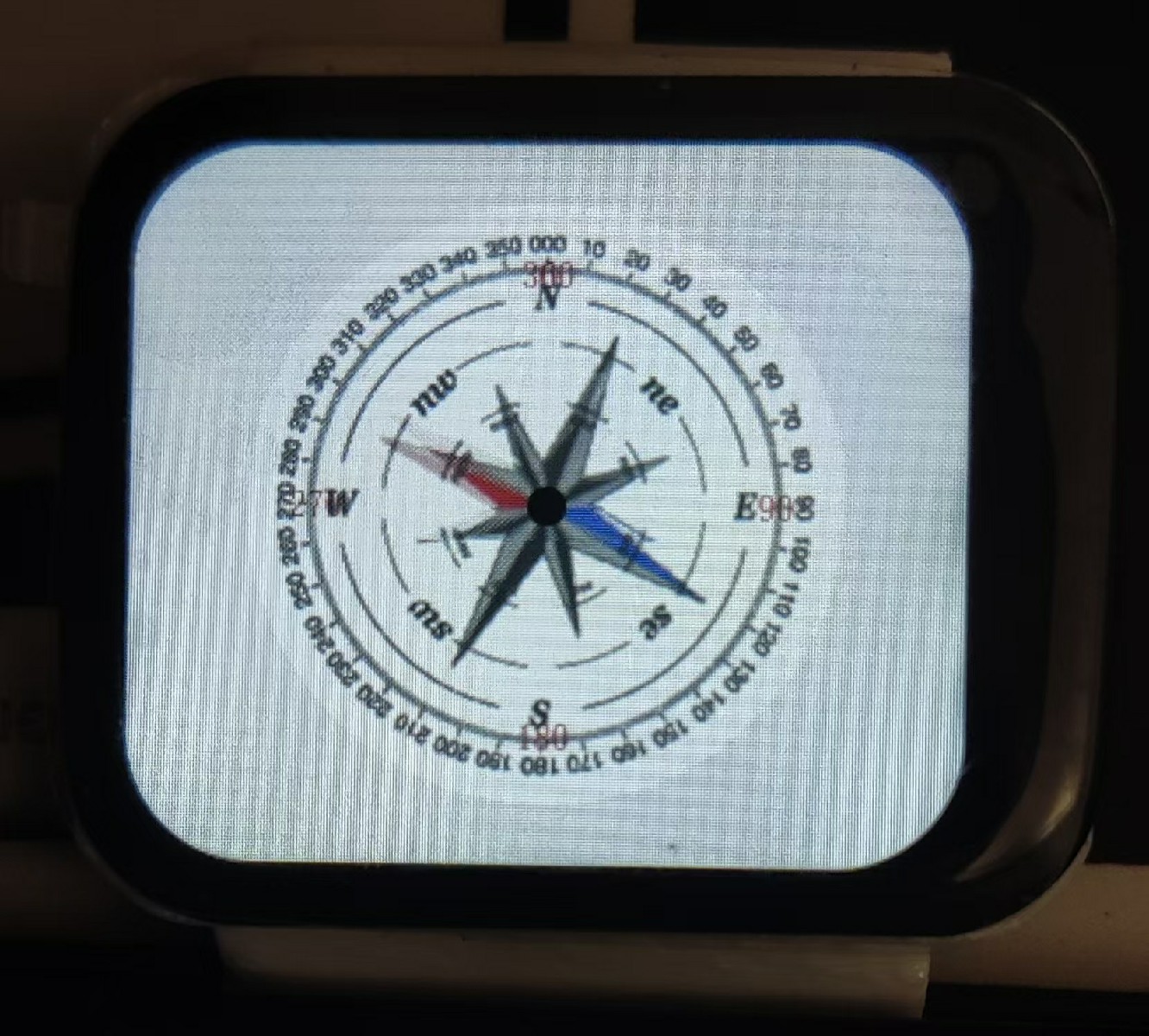
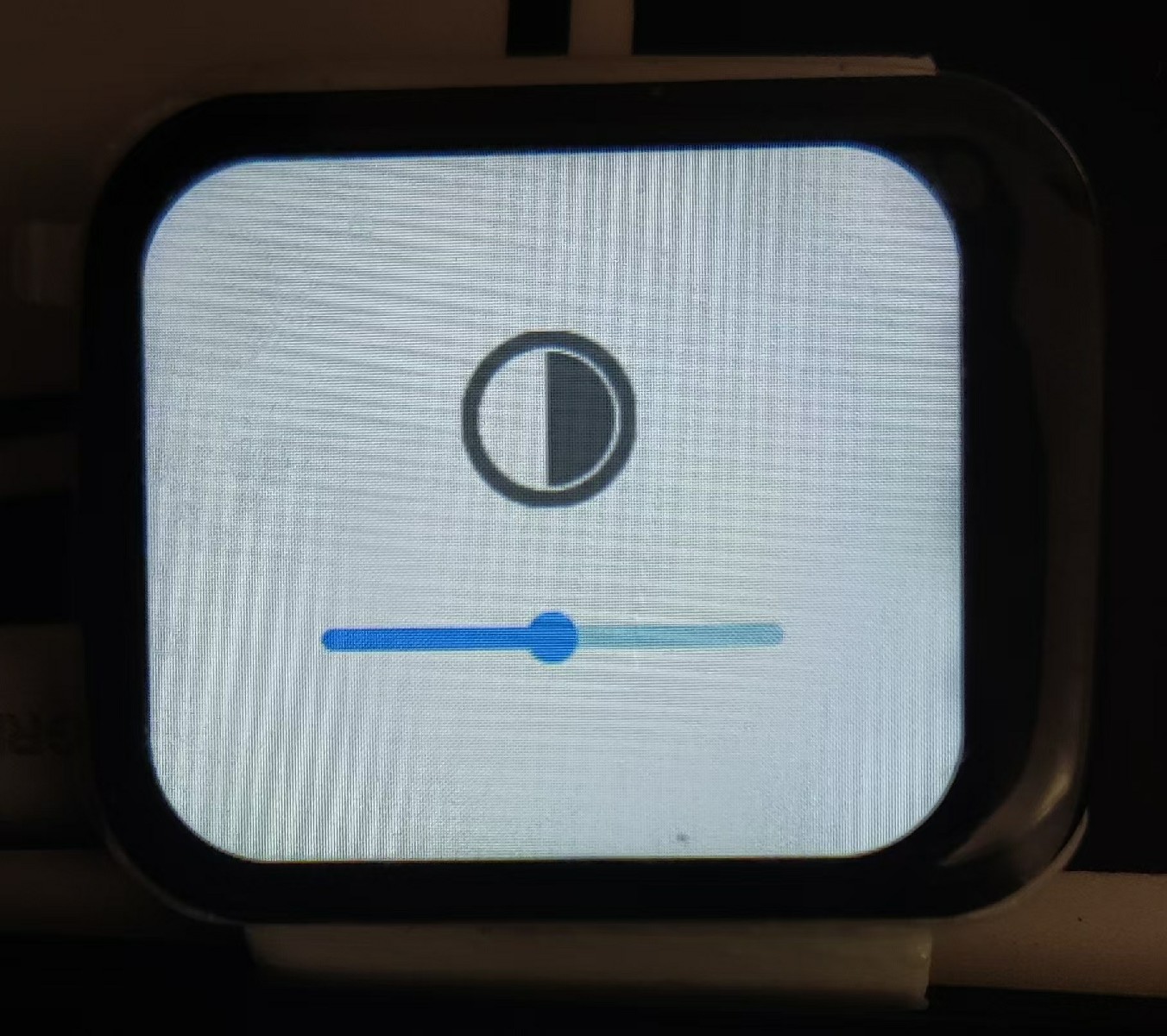
1. Function pages (sensors, compass, cloud platform control page (incomplete), settings (brightness adjustment));

2. Temperature and humidity collection, calculation and display of temperature, humidity, and perceived temperature;
3. Barometric pressure collection, calculation and display of altitude corresponding to the current atmospheric pressure;

4. Accelerometer sensor, enabling wrist-twist control for UI switching (incomplete);

5. Magnetic field sensor, calculating and displaying orientation (requires 5 seconds of 360° rotation for calibration before use; minimize magnetic field interference from surrounding electronic devices during calibration);
6. Screen brightness adjustment;
7. Calculation and display of remaining battery power;
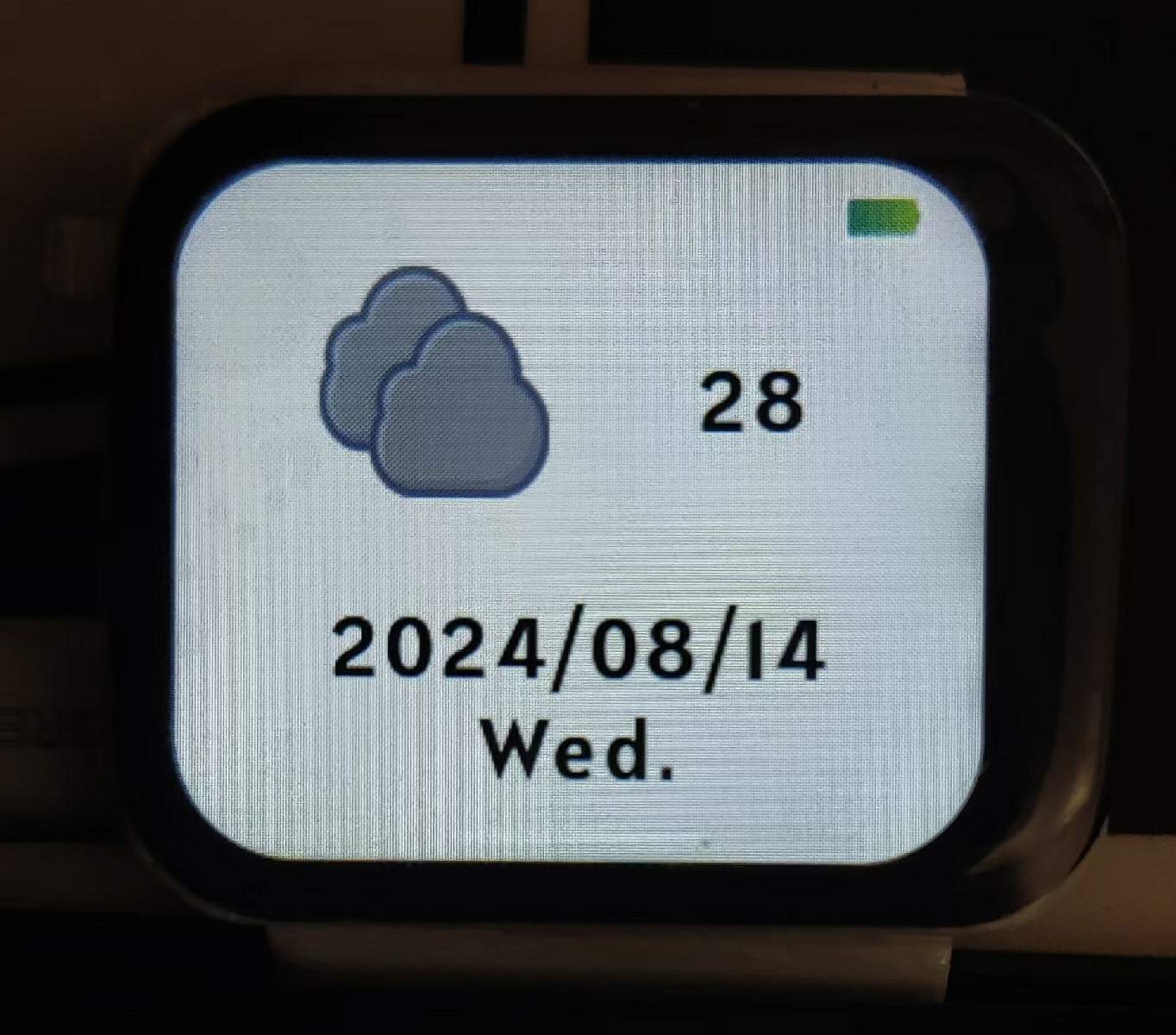
8. Obtaining network time, updating local time and displaying it;
9. Obtaining network weather and displaying it;
11. The screen turns off after 8 seconds by default, and the entire device automatically goes into sleep mode after 15 seconds (swipe to wake the screen when not in sleep mode, press the side switch to wake it up after sleep mode; the 460mAh battery can last three to four days on a full charge);
12. A short press of the side button returns to the watch's home screen, and a long press for 1 second restarts the watch.
#### System Architecture System Architecture Description

#### Installation Tutorial
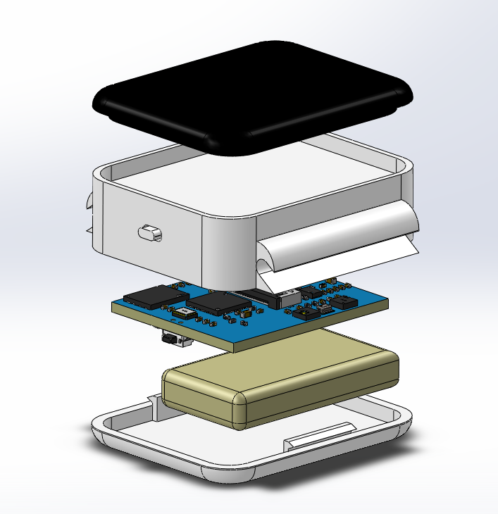
1. The hardware circuit of this project is developed using JLCPCB Professional Edition EDA. 1. Most original components can be purchased from LCSC. For other materials that are unavailable or too expensive on LCSC, you can check the Taobao purchase links in my BOM list; 2. LCSC offers free 4-layer prototyping. Remember to select 1mm board thickness; 3. Since the hardware circuitry uses mostly small packages, if you are not confident in your soldering skills, it is recommended to create a stencil or SMT while purchasing materials from LCSC; 4. This project code is developed using ESP-IDF + VS Code. After correctly deploying the ESP-IDF development environment in VS Code, open the project, compile and check for errors, then click "Burning" and select the chip model ESP32S3 for serial port burning (search online for methods; many tutorials are available); 5. The Gitee repository also contains STL files for the watch case. If needed, you can download them and 3D print the case.
#### Instructions for Use
1. By default, the watch needs to connect to the internet to synchronize network time after being powered on. To ensure normal operation, please modify your Wi-Fi SSID and PSWD in main/sys/wifi/wifi.h before flashing. 2. If you want to use the OneNET cloud platform project, please set the function enable macro MQTT_ENABLE to 1 in main/sys/mqtt/mqtt.h and modify the OneNET cloud platform information in the file to your own information. 3. When using the weather API, please be sure to modify the Xinzhi Weather API URL in the main/app/API/api.h file to your corresponding city and fill in your applied APP KEY (https://www.seniverse.com/api). 4. The lvgl business code is located in the main/ui folder. The lvgl project code of this project is mainly generated by GUI Guider. The lvgl version is 8.2, and the GUI Guider version is 1.6.1 (this version is older and can be downloaded from the Tools folder in the Gitee repository of this project).
show.mp4
Assembly.mp4
BOM.xlsx
Visualized BOM (Bill of Materials) table.html
Shell.zip
Firmware.zip
PDF_Deli Watches.zip
Altium_德丽制Watches.zip
PADS_Deli Watches.zip
BOM_Deli Watches.xlsx
93161
electronic


 京公网安备 11010802033920号

 PLAD15KP8.5CATR


