Function Overview: For voltage measurement, it supports 0-30V voltage ADC measurement with a display accuracy of 0.1V and 0-3V precise ADC measurement with a display accuracy of 0.01V; for current measurement, it supports 0-3A current ADC measurement with a display accuracy of 0.01A. It can simultaneously and in real-time detect voltage and current. It has circuit protection functions, preventing mistake-proofing and reverse connection.
Voltage Measurement Wiring: Connect the CH1 terminal to the circuit under test, and connect the positive and negative terminals according to the markings on the circuit board. When verifying the voltage displayed on the upper digital tube with an external voltmeter, connect the probes to the rubber sockets at both ends of CH1, with the red and black probes connected to the banana plug
as marked on the circuit board. Current Measurement Wiring: Connect the CN1 terminal to the circuit under test, and connect the positive and negative terminals according to the markings on the circuit board.
When verifying the voltage displayed on the lower digital tube with an external ammeter, connect the red CN2 terminal (port 1) to the positive terminal, the banana plug to the red ammeter probe, the right banana plug to the black ammeter probe, and the black CN1 terminal to the negative terminal. Ensure the current flow direction is: TA, multimeter, i+, resistor R0, GND.
Voltage Calibration: Connect according to the measured voltage. Adjust the input voltage to 5V. The multimeter will display 5V. Press K1. The upper digital display will show "V.05", and the lower digital display will show the voltage value before calibration. Press K2 to complete the 5V calibration. Adjust the input voltage to 15V. The multimeter will display 15V. Press K1 twice. The upper digital display will show "V.15", and the lower digital display will show the voltage value before calibration. Press K2 to complete the 15V calibration.
Current calibration wiring: Follow the current measurement wiring instructions. Adjust the input current to 0.5A. The multimeter will display 500mA. Press K1 three times. The upper digital display will show "A.0.5", and the lower digital display will show the current value before calibration. Press K2 to complete the 0.5A calibration. Adjust the input current to 1.5A. The multimeter will display 1.5A. Press K1 four times. The upper digital display will show "A.1.5". Press K2 to complete the 1.5A calibration.
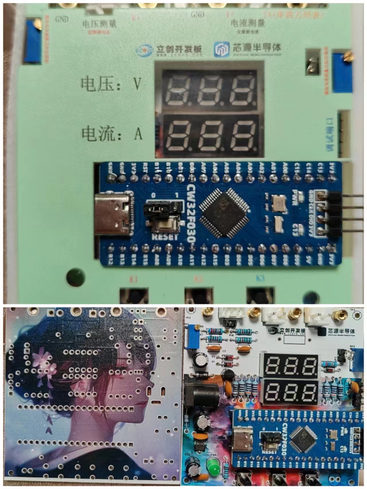
The circuit is mainly divided into six parts: power supply circuit, voltage and current sampling circuit, voltage and current analog sampling and calibration circuit, digital tube display circuit, key and LED indicator circuit, and peripheral interface circuit.
A brief description of the filter circuit hardware design:
Capacitor design follows the principle of large capacitors first, then small capacitors; electrolytic capacitors filter low-frequency waves, and ceramic capacitors filter high-frequency waves.
Circuit protection: Schottky diode 1N5189 for reverse connection protection, a series 10-ohm resistor for overcurrent and short-circuit protection, a 1K resistor in series at the ADC for current limiting protection
, and a sampling resistor calculated based on voltage divider. 1N4148 is used as a clamping diode to protect the MCU pin
current detection, which is essentially voltage measurement. The design current is 0-3A. The sampling circuit needs to be connected in series with the circuit under test. The voltage drop at the small resistor R0 is measured by the ADC, and the circuit current can be calculated from the resistance value of R0 itself.
This PCB does not use full-board copper plating; it uses a single-point grounding method with series connection within groups and parallel connection between groups. Local widening and filling of the parallel main ground line ensures the same potential at the grounding points. Power ground and signal ground are separated.
The current sampling resistor R0 is connected using the Kelvin connection method to eliminate the influence of line resistance and contact resistance on the measurement results.
Through this learning experience, I have just mastered the use of Keil 5 software. Since I haven't fully understood the software part yet, I won't go into the design principles of the software. The compiled HEX file is in the appendix. Learning document link: https://wiki.lckfb.com/zh-hans/dwx-cw32f030c8t6/training/voltammeter-bootcamp/voltammeter.html
The 3D shell has some flaws; the height of the screw posts needs to be modified
. Keil 5 compilation may cause errors; CMSIS version 5.40 is required. The compiler is VC5. Currently, installing the community edition of Keil 5 from the official website does not include the VC5 compiler; you need to download and install it yourself. Specific tutorials can be found on Bilibili or in the Keil official Q&A section.
Circuit verification videos are in the appendix. Since my multimeter is inaccurate and I don't have a reference at home, it is not calibrated yet. Calibration will be done when a voltage reference becomes available.


 京公网安备 11010802033920号

 BTA06-600TW


