I. Design Background
An ADC (Analog-to-Digital Converter) is an indispensable key component in electronic systems. It converts continuous analog signals into digital signals, enabling digital processing and analysis. ADCs play a crucial role in signal conversion, measurement and data acquisition, control system input, and communication and signal processing. Their widespread application promotes the intelligent and precise control of electronic equipment across various industries, and is one of the key factors driving modern technological progress. Digital voltmeters and ammeters combine ADC technology with circuit measurement principles, accurately converting analog voltage and current signals into digital displays for easy reading and analysis by electronic engineers. This device not only improves the accuracy and efficiency of circuit measurements but also helps engineers better understand circuit behavior, serving as a powerful tool for electronic design and troubleshooting, and playing a vital supporting role in the work of electronic engineers. In product applications, digital voltmeters ensure the accuracy and safety of circuit design, while also providing strong support for product quality control and subsequent maintenance.
II. Project Features: The project
adopts a core board plus expansion board design concept, using plug-in components to simplify learning and deepen exploration.
The core board uses the domestic Wuhan Xinyuan Semiconductor CW32 as the main controller, while also being compatible with other similar development boards; however, the CW32 has advantages.
The project is highly comprehensive and practical, and after completion, it can be used as a desktop instrument.
The project offers abundant learning materials, including circuit design tutorials, PCB design, code programming learning, and training for engineers' debugging skills.
III. Important Hardware Design
: 3.1 Power Supply Circuit

3.2 Main Controller Selection:
To reduce the learning cost, this project uses the LCSC·Diwenxing CW32F030C8Tx development board (core board) as the main controller, but this does not mean we will cover this section less. From the perspective of training engineers, the correct selection of the main controller is crucial, as it relates to the overall advantages of the project. Regarding the voltmeter and ammeter, the author conducted some debugging and testing using STM32/CW32 and some other 32-bit microcontrollers. This comparison is only with the STM32F103C8T6 as a reference for device selection, primarily to provide ideas and improve understanding.
The key advantages of the CW32 in this project include
: wide operating temperature range (-40~105℃)
, wide operating voltage (1.65V~5.5V, STM32 only supports 3.3V systems)
, strong anti-interference capabilities (HBM ESD 8KV, all ESD reliability reaches the highest international standard level (STM32 ESD 2KV))
, and a better ADC (12-bit high-speed ADC achieving ±1.0LSB INL 11.3ENOB), multiple Vref reference voltages (STM32 only supports VDD=Vref),
and stable and reliable eFLASH technology. The circuit diagrams include:
3.3 Voltage Sampling Circuit,
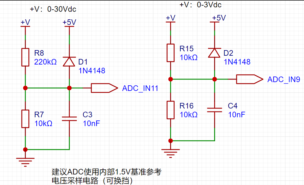
3.4 Current Sampling Circuit,

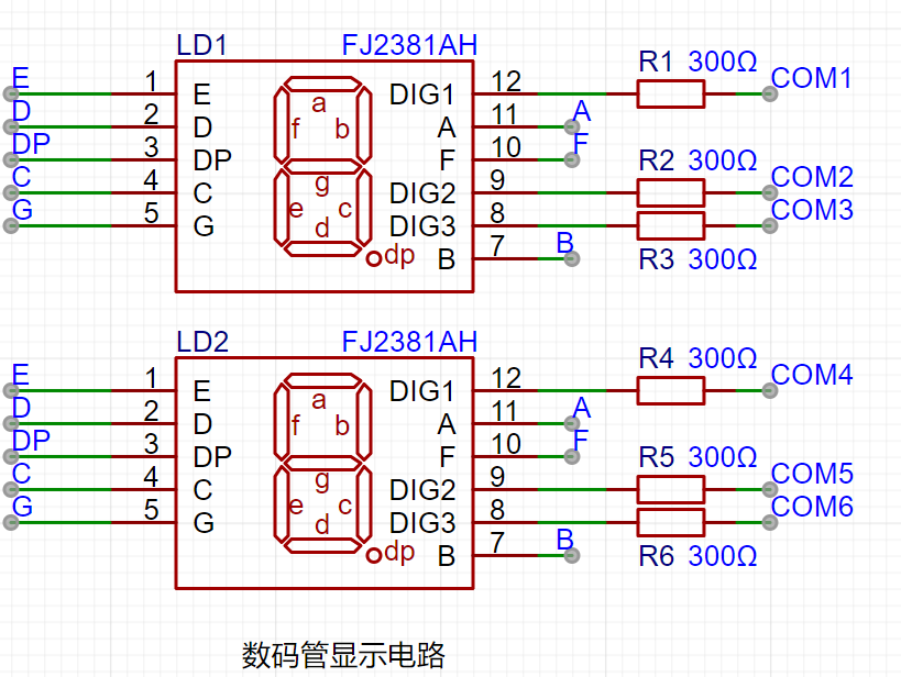
3.5 Digital Tube Circuit,
3.6 Keypad
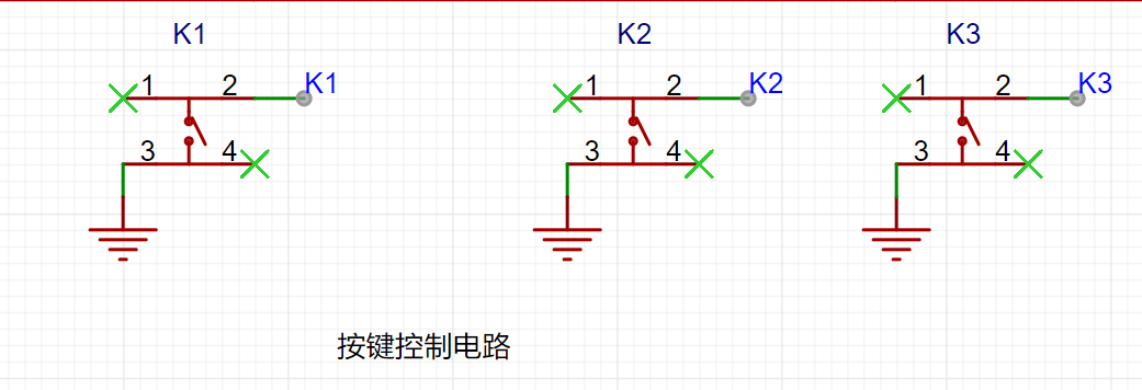
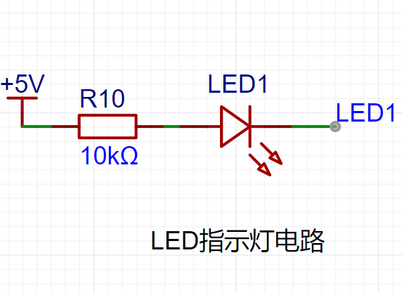
Circuit, 3.7 LED Indicator Circuit, and
3.8 Voltage Measurement Calibration.

The fourth point discusses the use of color
silkscreen printing, noting that the effect is truly perfect.

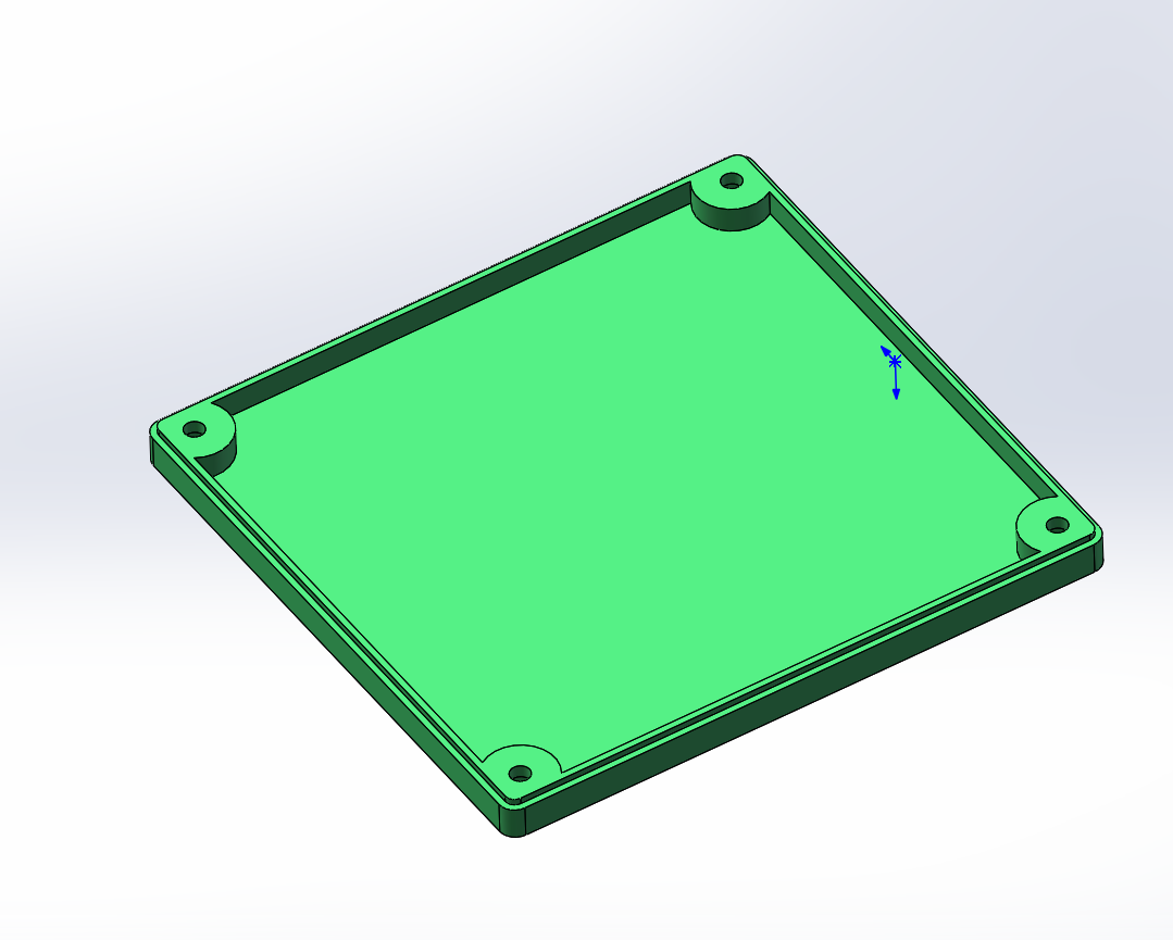
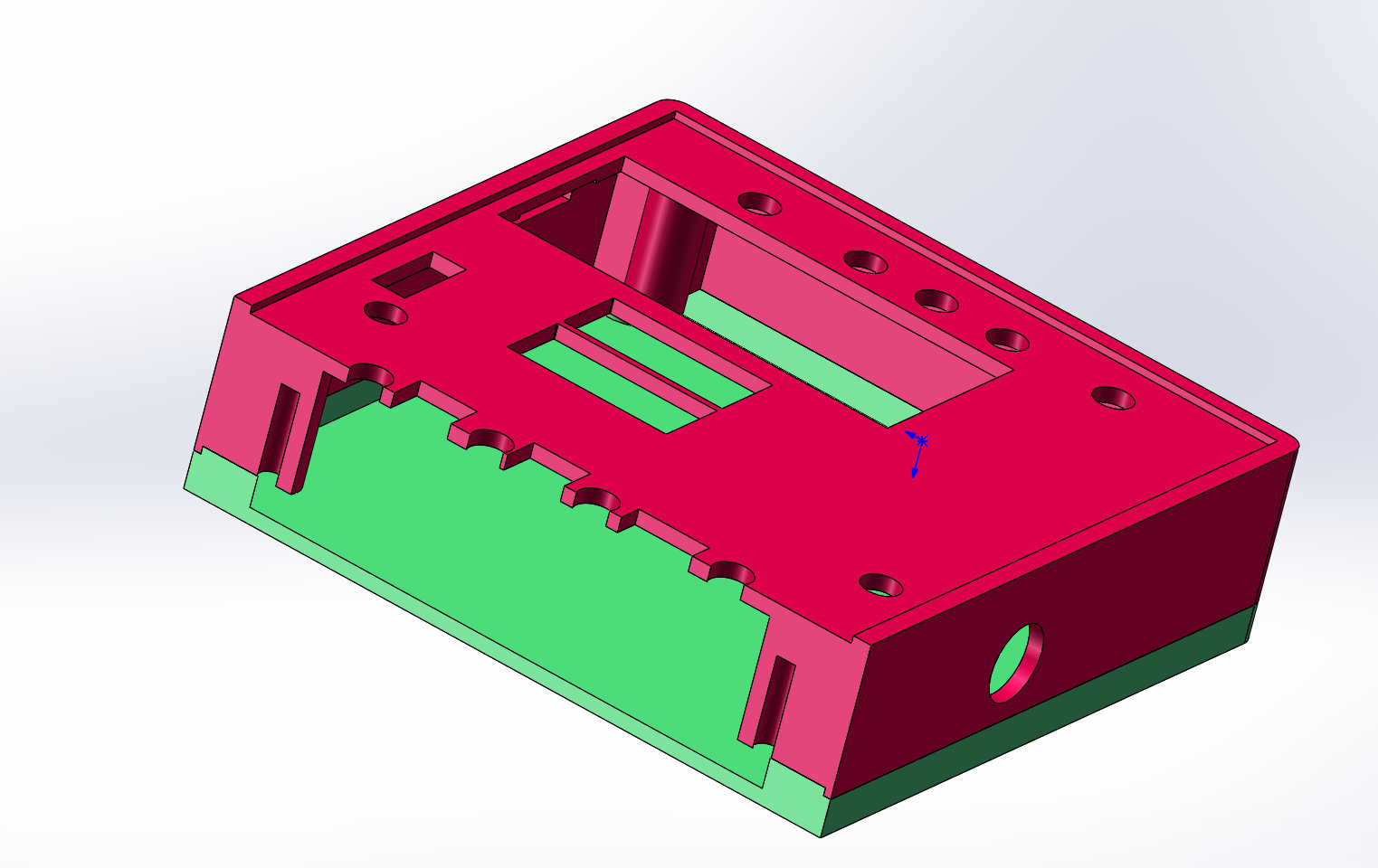
The fifth point concerns the casing design.
The bottom of the casing had some interference after the PCB was installed, making it impossible to install the back cover. However, the upper part did not affect the installation of the panel.
This casing design uses SolidWorks, with the panel embedded in the top cover.
I had considered the button issue when designing the casing. I could have bought an extended button, but I forgot to buy it. The actual product without the extended button was not shown in the picture. Also, I didn't buy the wiring for the measurement connection. I directly soldered some wires as a substitute.


Six: Panel Design.
The panel was drawn by exporting the plan view from SolidWorks, importing it into CAD, deleting unnecessary lines, and then importing it into JLCPCB panel design software. There were many mistakes and detours along the way, but I finally completed the panel design by referring to JLCPCB tutorials.
Considering that the development board might protrude, two panel designs were made. One design has a hole for the development board, and the other does not. There were still some problems during the final installation. I shortened the jumper caps on the development board to install it.
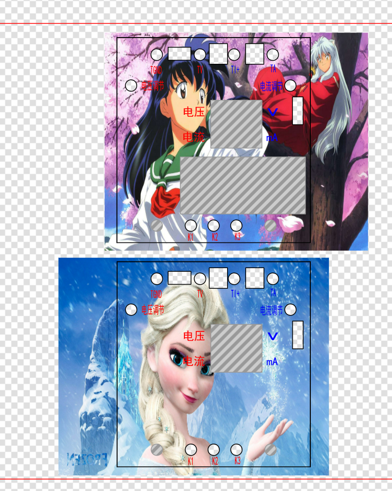
The finished result is very good. Because my child likes Elsa. The final product features Princess Elsa.
Seven: The program took many days to burn. It kept reporting various errors, wasting a lot of time. I initially thought of getting help from others to burn it, but I forced myself to do it. I planned to verify it step by step according to the tutorial, but there were too many errors. I had never used Keil software before, making it extremely difficult. Later, I repeatedly watched the tutorial materials, gradually reducing the errors. Finally, through my own learning and repeated viewing of the tutorial, I finally burned the final program. Then, when I tried to go back and verify other experiments, I found many errors. Due to time constraints, I only burned the final program.
Through this experience, I discovered many problems, which was quite rewarding. Even afterward, someone in the group asked me about a problem they encountered, and I was able to answer their question. Not bad!
PS: Don't print the bottom of the 3D shell. I'll upload it as an attachment. The other designs are fine. Hopefully, this provides a way to coordinate the top and bottom.
Okay, that's all for now.


 京公网安备 11010802033920号

 5082-7408-EC000


