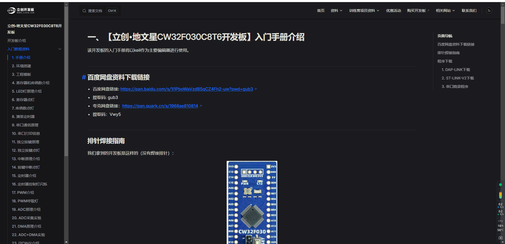
 Here is the LCSC development board documentation link: https://wiki.lckfb.com/zh-hans/dwx-cw32f030c8t6/beginner/
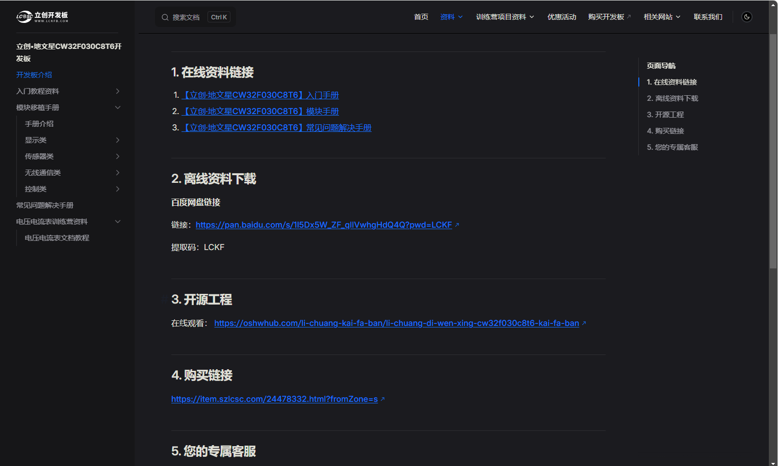
 Unfortunately, the documentation does not cover this. This document introduces how to connect devices to Alibaba Cloud. Therefore, I researched and learned to improve the device connection process for Alibaba Cloud IoT, enabling network data transmission and reception. Below are some debugging steps I took to connect devices to Alibaba Cloud, partially referencing information from a CSDN blog
  Following this blog, I learned how to configure the Alibaba Cloud platform and completed the device setup and triplet parameter acquisition, which is a crucial step in connecting devices to Alibaba Cloud. (Based on information from LCSC development...) The program that passed the test showed code linking to Alibaba Cloud, including a section for parsing Alibaba Cloud triples. However, during actual use, the command would get stuck at the triple parsing stage, possibly due to a problem with my code. This remained unresolved. But in this blog post, I found that the author used computer software to parse Alibaba Cloud device triple parameters.
 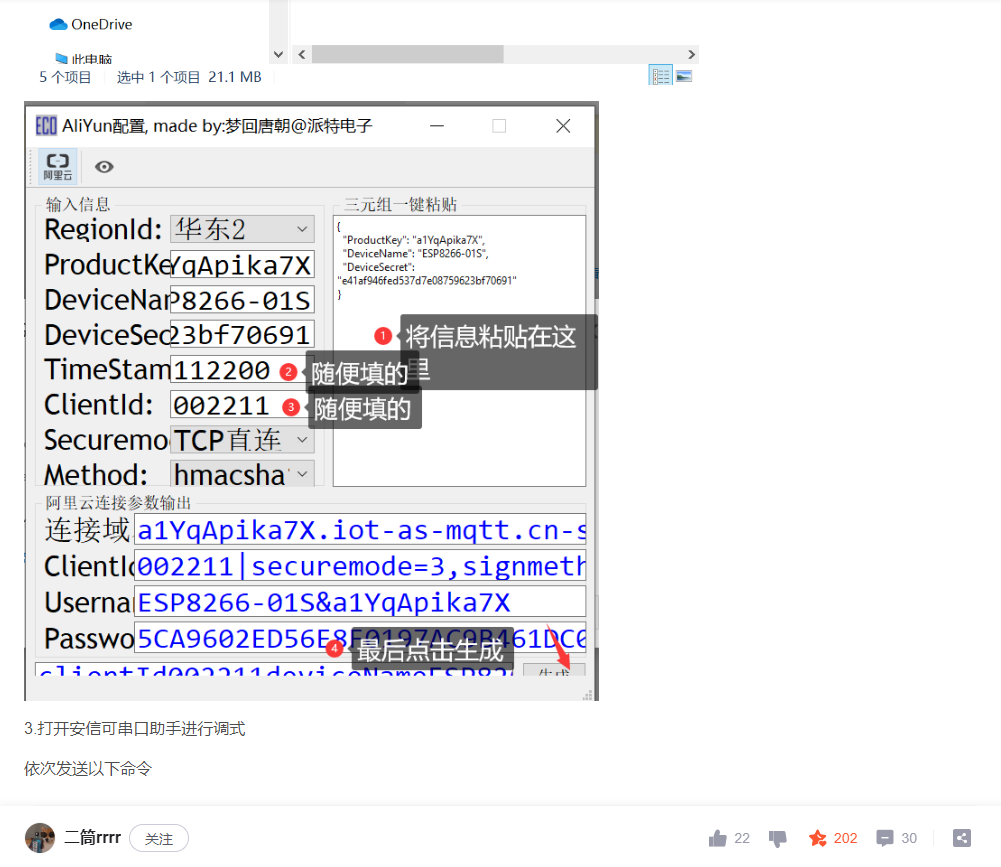 Therefore, I modified the Alibaba Cloud triple parameter parsing code in my program, commenting it out and replacing the output with the three data points parsed by the computer software. This allowed the device to connect to Alibaba Cloud and upload data via subscription. It also allows the device to receive data sent from Alibaba Cloud via serial port. When printing out the data,
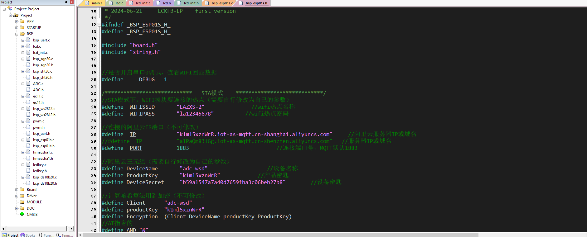
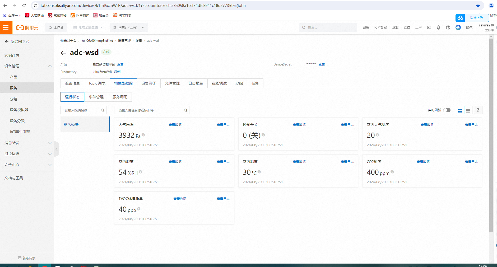 please note that after establishing the device via Alibaba Cloud, you need to obtain the triplet parameters and then use computer software (which will be packaged in the attachment) to parse and fill them into the corresponding location in the program. Refer to the source code packaged in my attachment. In addition, this location in the program needs to be run according to my modifications to ensure success. Otherwise, the program will freeze.
 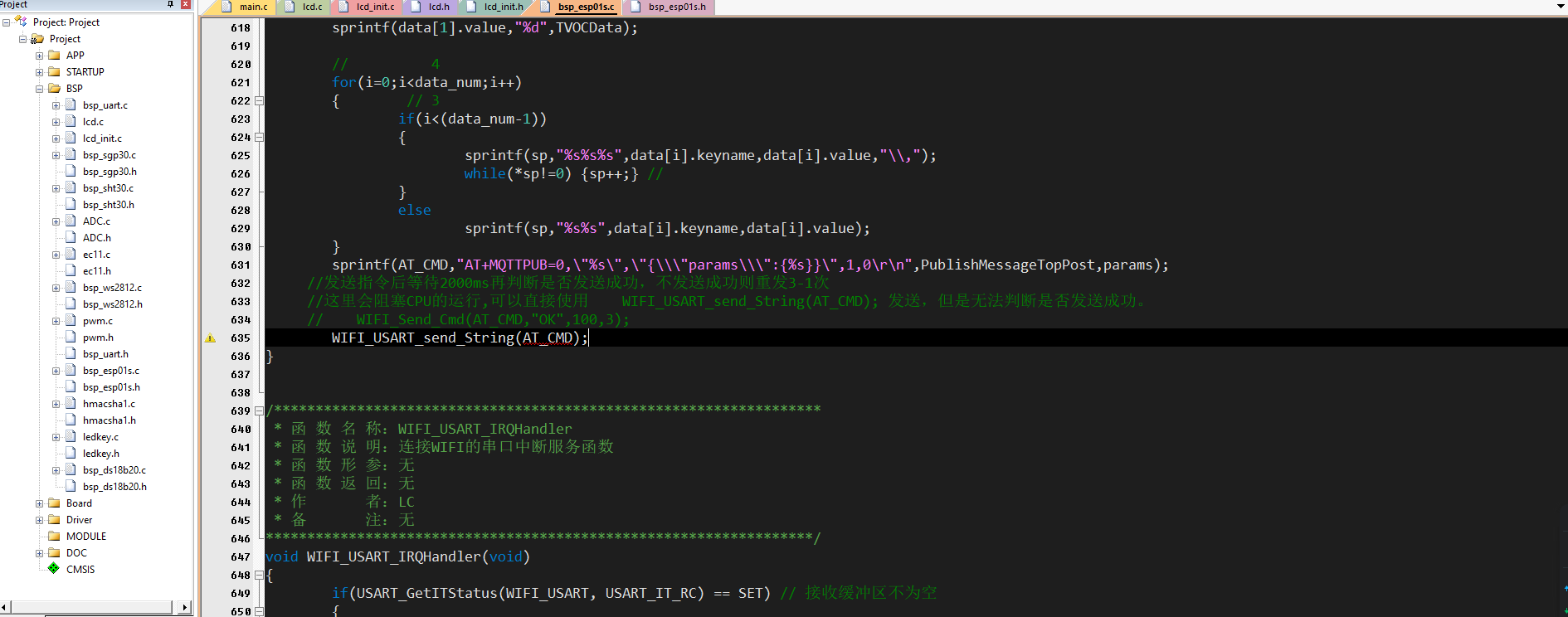 Here is the Alibaba Cloud platform website: https://cn.aliyun.com/
 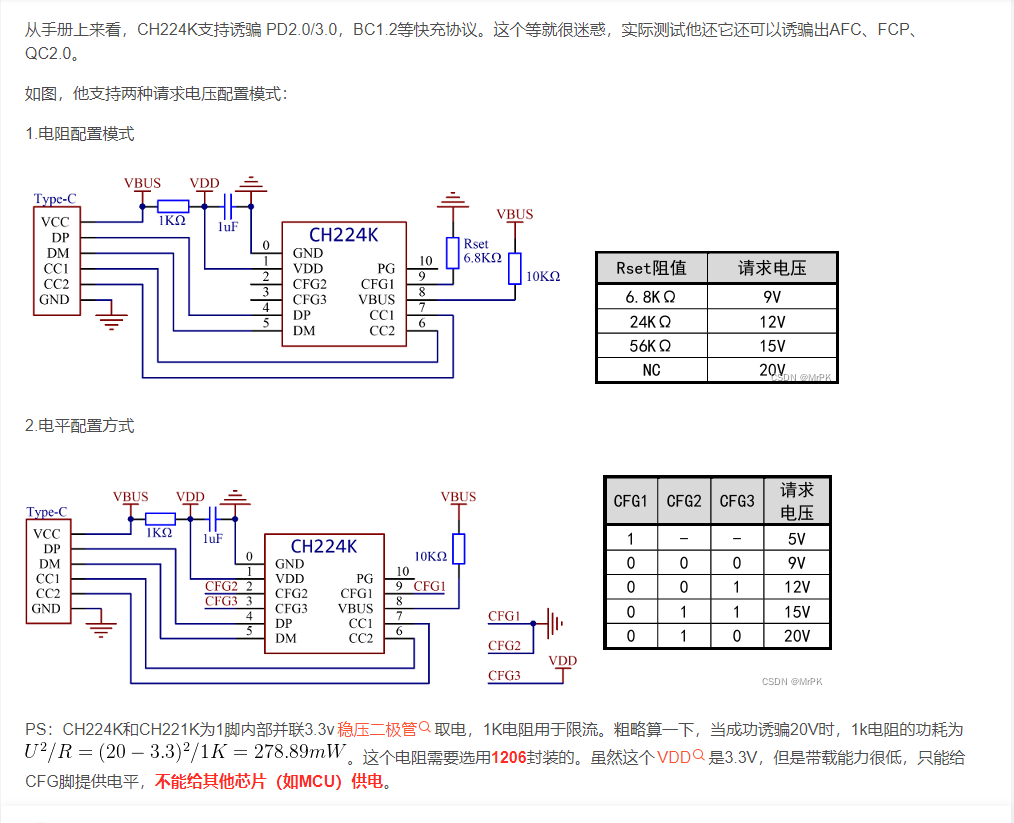 I chose level control. Regarding the 1K current limiting resistor, I used four 4.7K resistors in parallel to achieve the effect of heat dissipation and power distribution.
  A 9k and 2k resistor are connected in parallel to divide the voltage, and the microcontroller's I/O port controls the level, allowing different protocol chargers to be deduced to output their voltages.
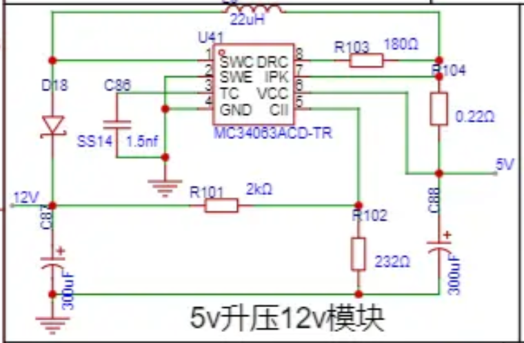
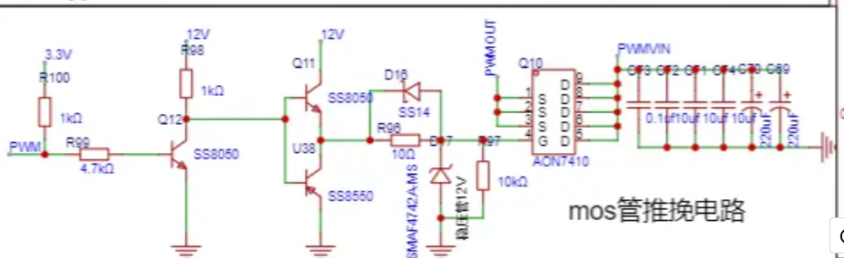 These circuits, combined with the BUCK circuit, control the output voltage induced by the charger to achieve an adjustable voltage, realizing a desktop-level adjustable voltage source design.
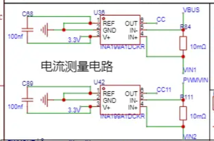
 7. Serial Communication Circuit Design:
 During the design process of the initial 5V1A charging circuit, some problems were discovered. For example, there was a wiring error in the 5V to 12V boost circuit, which was solved using a flying wire method. However, the power meter measurement circuit and the PD/QC decoy circuit were connected together, causing the power meter to malfunction. After removing the PD/QC decoy circuit, the power meter functioned normally. Additionally, the MOSFET could only output a maximum of about 9V after being turned on. Furthermore, the PWM pulse width amplitude adjustment was not ideal; the voltage step was directly fine-tuned from 4V to 9V, but irregular and difficult to control from 0V to 4V. This problem remains to be solved. All hardware circuit problems encountered have been addressed by redrawing the schematic and PCB layouts.
 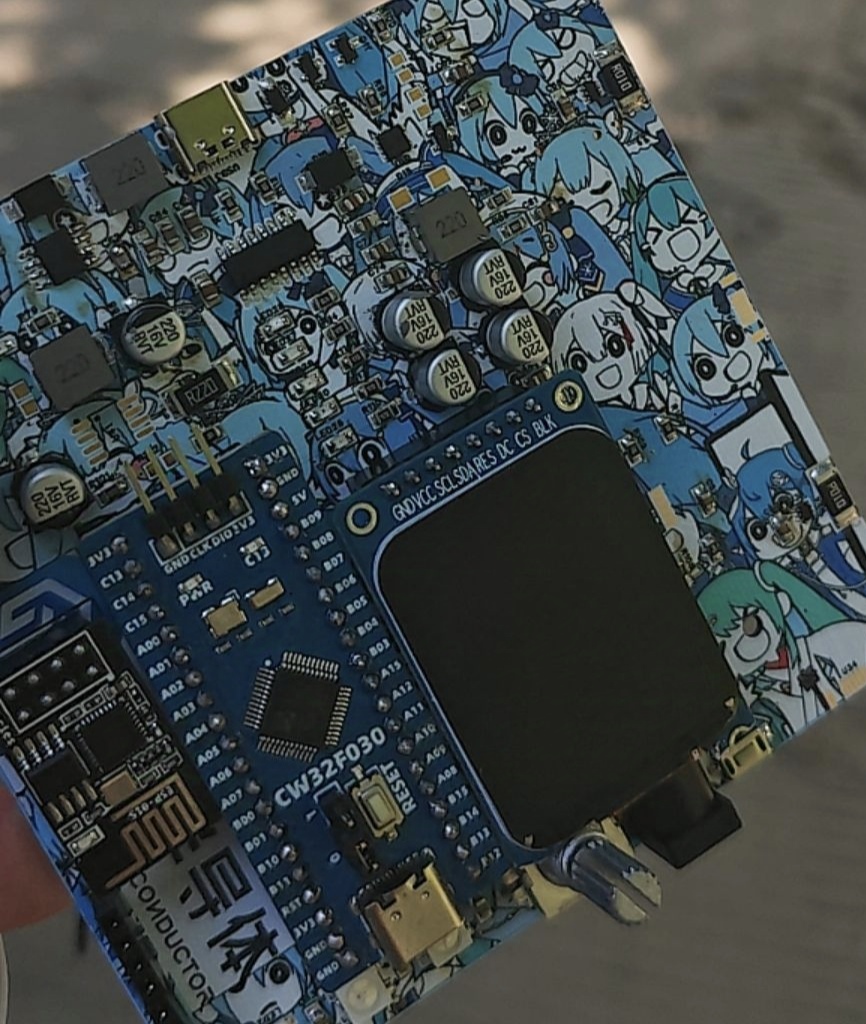 This is a physical verification image
 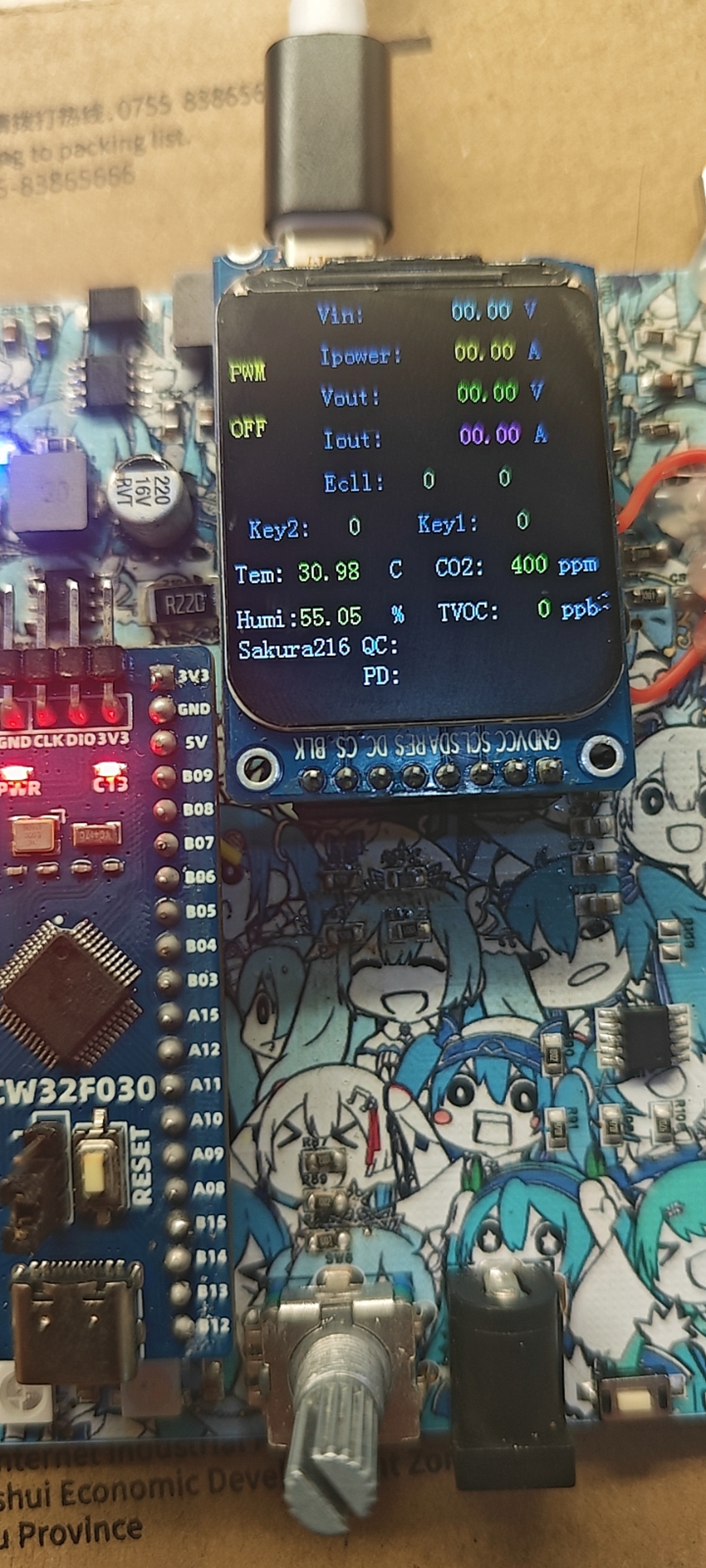 For those who want to replicate this, the program needs
  to be modified in the lcd_int.h file. The program is set to connect to the network by default upon startup and then the environment... When collecting data and reporting it to the Alibaba Cloud IoT platform, please note the following: The Wi-Fi name I set in the program is LAZXS-2, and the password is la12345678. Failure to modify this will cause the program to get stuck during initialization, preventing the device from powering on. You can manually set the same name and password for the hotspot using your mobile phone to allow the device to initialize successfully and start running normally. The program also supports AP mode, where the device generates a hotspot, and after connecting with a mobile phone, the corresponding app is opened to complete the interaction between the phone and the device. For details, please refer to the LCSC CW32 Geostellar datasheet. If you need to change it to your desired Wi-Fi network, modify the location as shown in the image,
 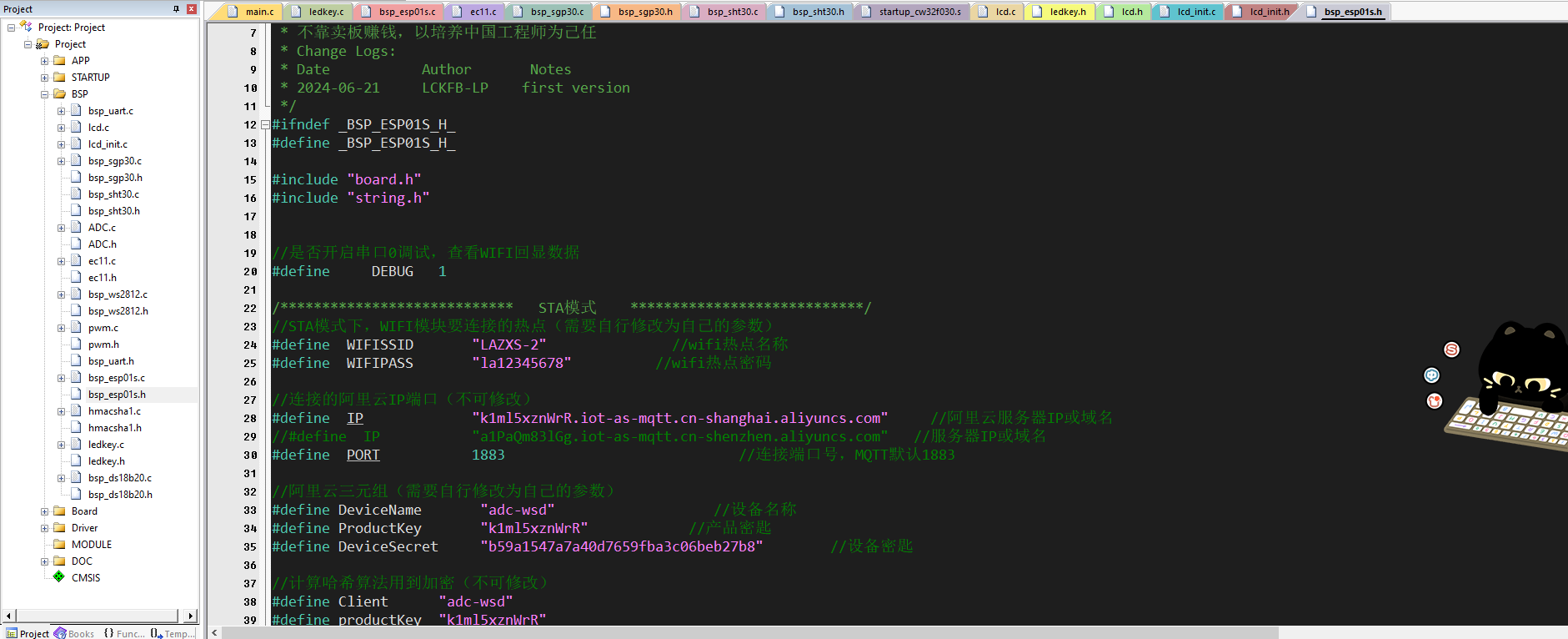 and then press the device button key2 to enter mode two. In this mode, the device will disconnect environmental data sampling, as discovered during debugging. Sampling environment data can interfere with voltage and current measurements. In this mode, the device can be used as a power meter. Since the modified board has not been verified, according to the modified board's instructions
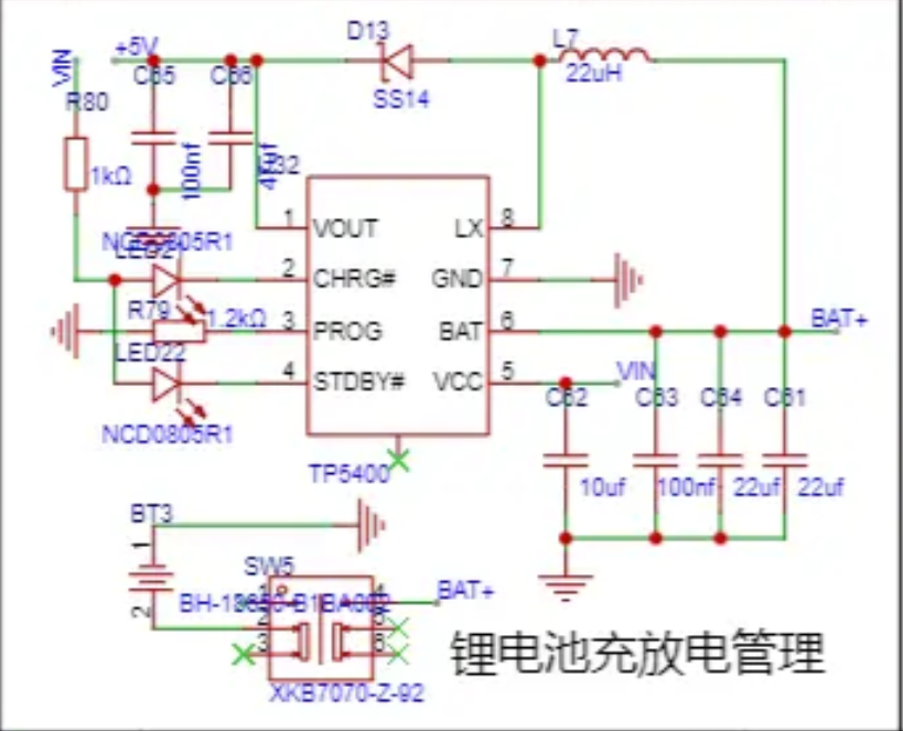
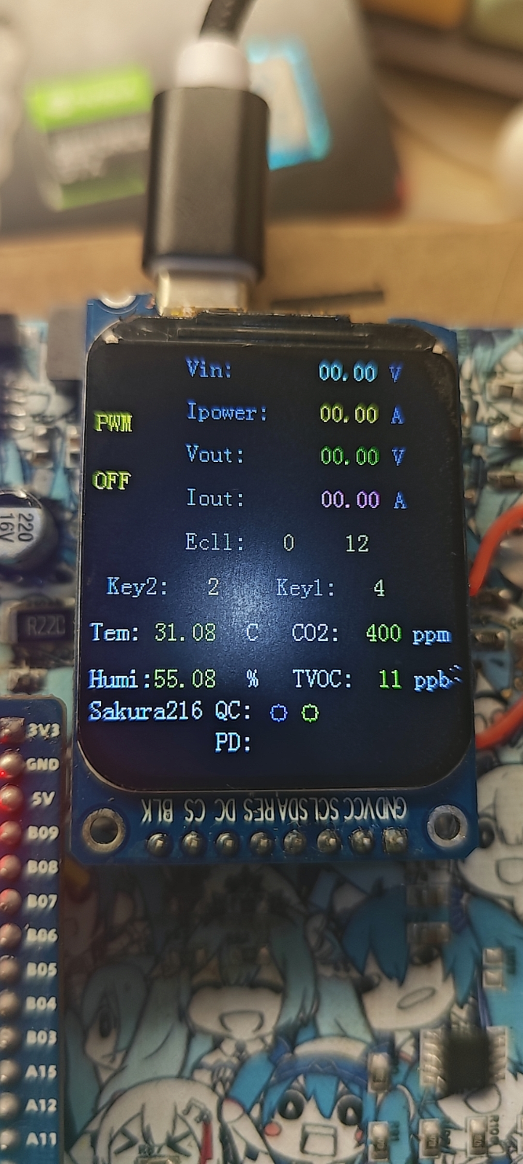
  , the outermost part on the right is the power meter measurement section. The top port is the input port, and the bottom port is the output port. If connected incorrectly, the current will not be displayed. After connecting as instructed, it can measure the voltage and current of the device. The central Type-C port is the charging and power supply port. The circuit design disconnects the lithium battery and supplies power through the 5V boost module if external power is used.
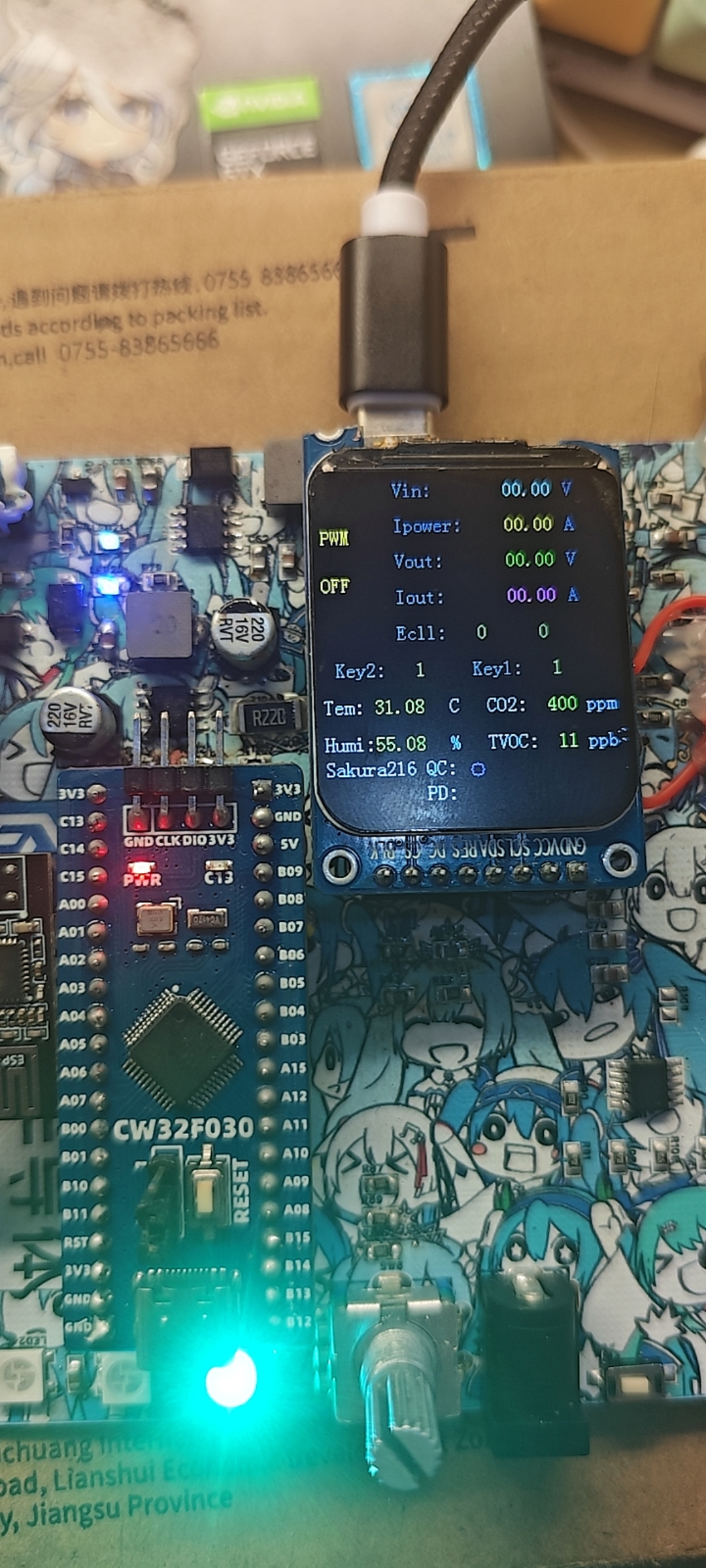
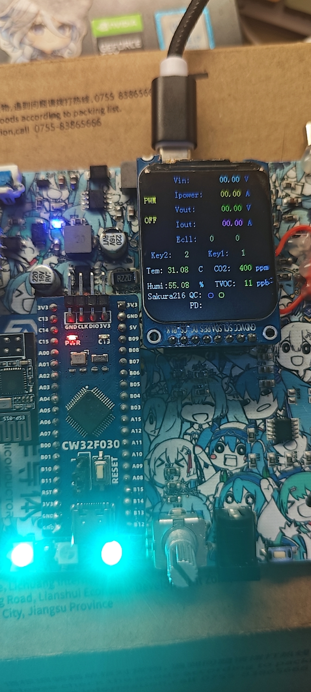
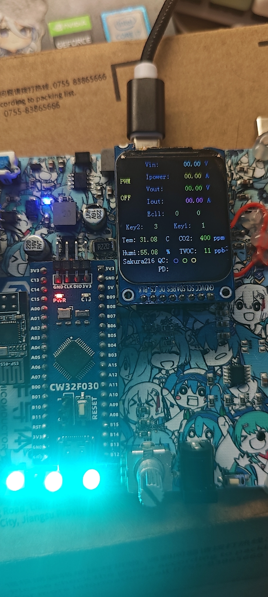
 Below are the device status images for the four PD spoofing levels
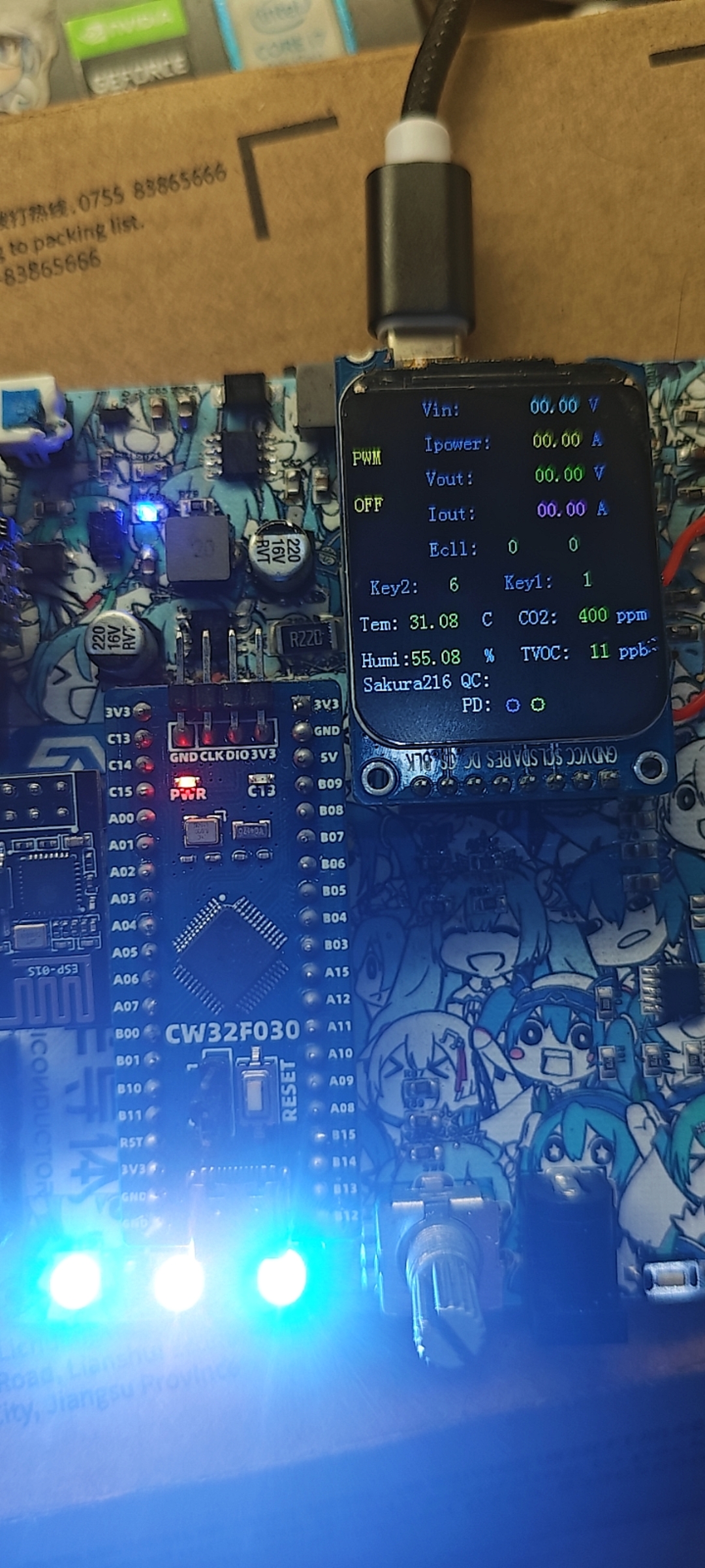

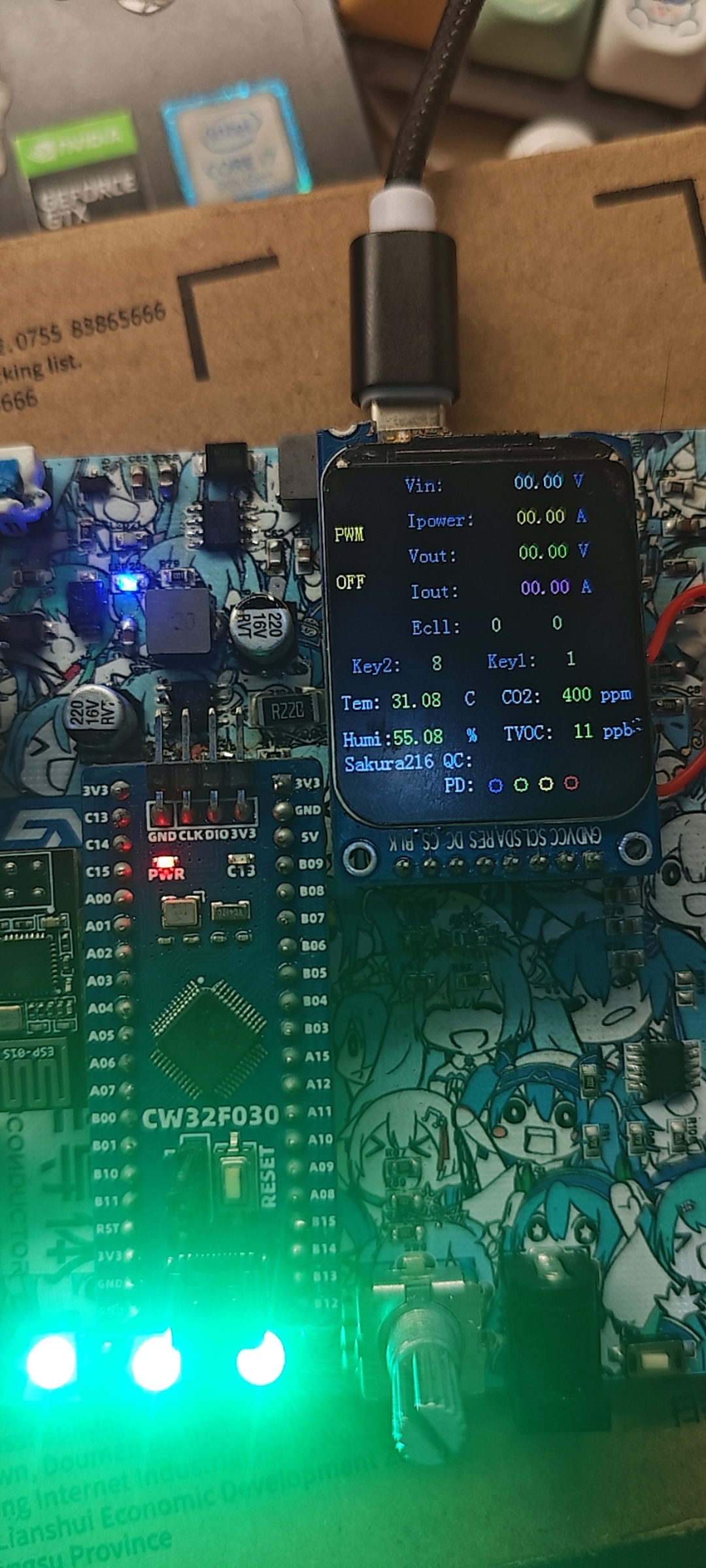 . Finally, the usage method of PWM pulse width modulation is as follows. The voltage spoofed as described above is generally one of four levels: 9V, 12V, 15V, and 20V. Sometimes a special voltage is required. A controllable voltage is output through the BUCK circuit. At this time, key2 needs to be pressed. When the screen displays the value 3 corresponding to key2, the corresponding PWM will be displayed as ON. If not, it will be displayed as OFF. At this time, the rotary encoder can control the PWM pulse width to achieve the purpose of voltage regulation.
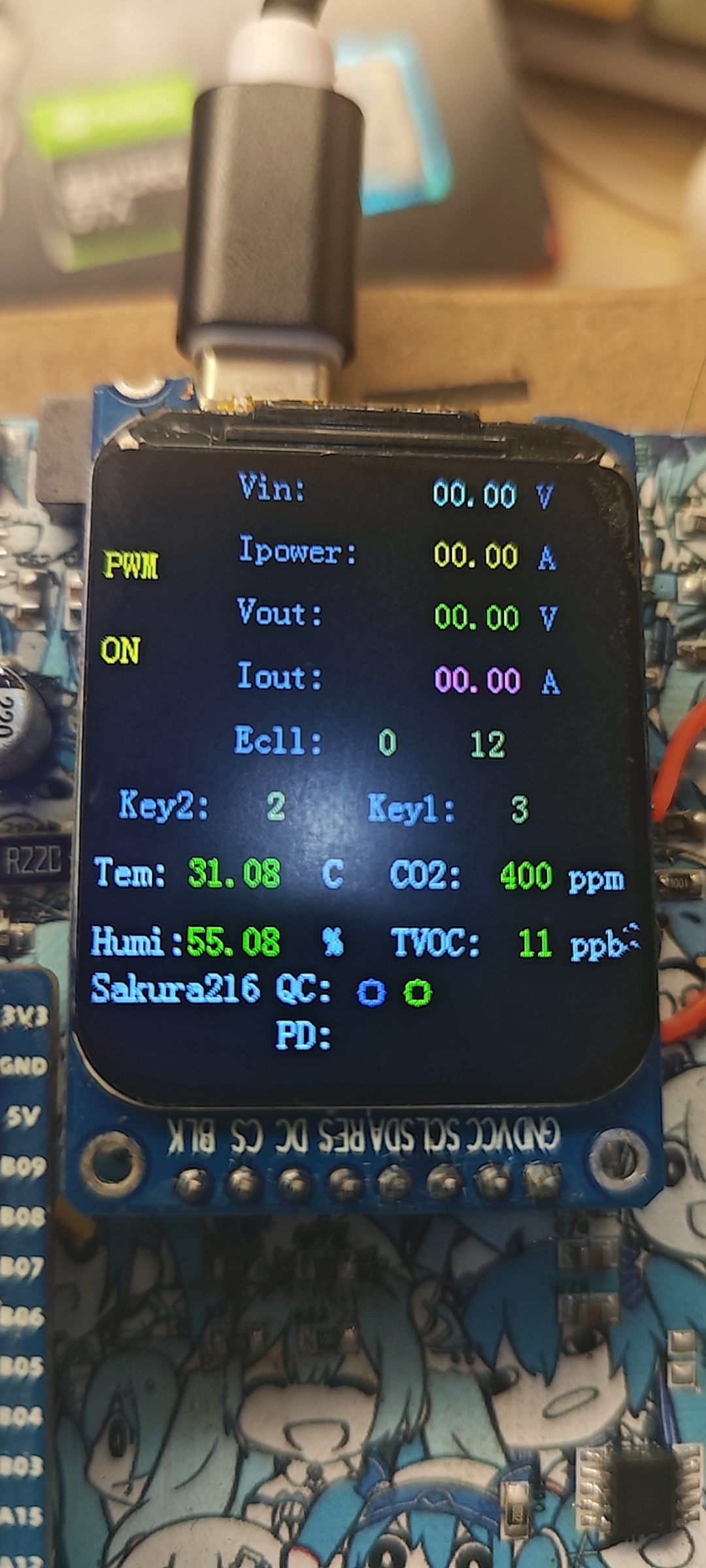

All reference designs on this site are sourced from major semiconductor manufacturers or collected online for learning and research. The copyright belongs to the semiconductor manufacturer or the original author. If you believe that the reference design of this site infringes upon your relevant rights and interests, please send us a rights notice. As a neutral platform service provider, we will take measures to delete the relevant content in accordance with relevant laws after receiving the relevant notice from the rights holder. Please send relevant notifications to email: bbs_service@eeworld.com.cn.
It is your responsibility to test the circuit yourself and determine its suitability for you. EEWorld will not be liable for direct, indirect, special, incidental, consequential or punitive damages arising from any cause or anything connected to any reference design used.
Supported by EEWorld Datasheet
EEWorld
subscription
account

EEWorld
service
account

Automotive
development
community

Robot
development
community

About Us Customer Service Contact Information Datasheet Sitemap LatestNews


Room 1530, 15th Floor, Building B,
No.18 Zhongguancun Street,
Haidian District,
Beijing, Postal Code: 100190
China
Telephone: 008610 8235 0740
 京公网安备 11010802033920号

 207610-6


