 Software configuration selects the appropriate burning method.
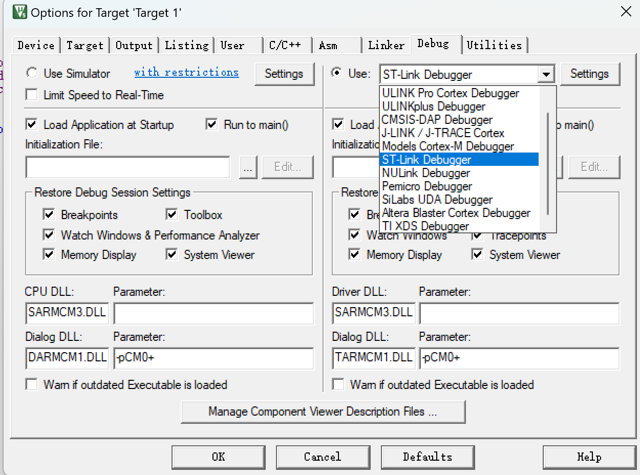
 1. Resistor value optimization: The resistance value of R27 (originally 220K) can be changed to 200K for more accurate measurement and to save on components (R28 is also 200K).
 Since I do not have an adjustable power supply, I can only adjust the potentiometer (R34), which is similar to changing the voltage division ratio to change the voltage value. The multimeter and digital tube change with the potentiometer rotation (verified).
  The software needs to be modified (the uploaded version has been modified, original: 220).
  If the program cannot be burned, please select the corresponding kernel. All compilation program warnings can be ignored.
 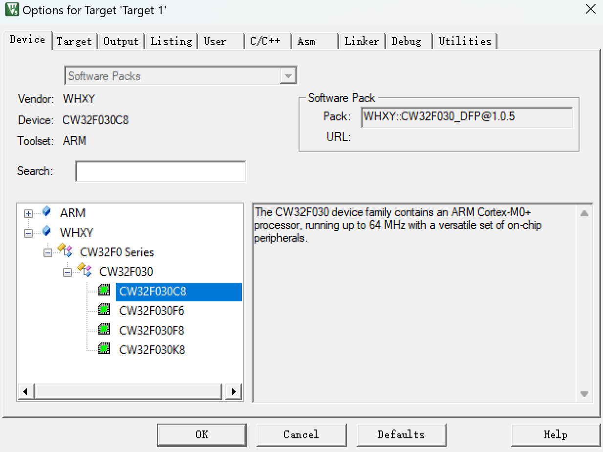 If you still cannot download, please refer to the technical document, Software Design - 3.2 Development Environment Setup.
All reference designs on this site are sourced from major semiconductor manufacturers or collected online for learning and research. The copyright belongs to the semiconductor manufacturer or the original author. If you believe that the reference design of this site infringes upon your relevant rights and interests, please send us a rights notice. As a neutral platform service provider, we will take measures to delete the relevant content in accordance with relevant laws after receiving the relevant notice from the rights holder. Please send relevant notifications to email: bbs_service@eeworld.com.cn.
It is your responsibility to test the circuit yourself and determine its suitability for you. EEWorld will not be liable for direct, indirect, special, incidental, consequential or punitive damages arising from any cause or anything connected to any reference design used.
Supported by EEWorld Datasheet
EEWorld
subscription
account

EEWorld
service
account

Automotive
development
community

Robot
development
community

About Us Customer Service Contact Information Datasheet Sitemap LatestNews


Room 1530, 15th Floor, Building B,
No.18 Zhongguancun Street,
Haidian District,
Beijing, Postal Code: 100190
China
Telephone: 008610 8235 0740
 京公网安备 11010802033920号

 1092-X-9931-D-1004


