Thanks to JLCPCB for providing the learning opportunity.
Thanks to the developers and Engineer Chen.
Thanks to Wuhan Chip Source.
For a simple replication and burning of the official source code,
please refer to https://wiki.lckfb.com/zh-hans/dwx-cw32f030c8t6/training/voltammeter-bootcamp/voltammeter.html
LCPCB CW32 Digital Voltage and Current Meter Expansion Board - LCPCB Open Source Hardware Platform (oshwhub.com)
1. Power Supply Circuit
ADC means converting continuous analog signals into digital signals, providing the possibility for digital processing and analysis. ADCs play an important role in signal conversion, measurement and data acquisition, control system input, and communication and signal processing. Their widespread application promotes the intelligent and precise control of electronic equipment in various industries and is one of the key factors driving modern technological progress.
Voltage and current are calculated through ADC sampling.
This project, like the official project, adopts a core board plus expansion board design concept, using plug-in components to simplify learning and deepen exploration.
The core board uses the domestic Wuhan Xinyuan Semiconductor CW32 as the main controller, while also being compatible with other similar development boards; however, the CW32 has advantages.
The project is highly comprehensive and practical, and after completion, it can be used as a desktop instrument.
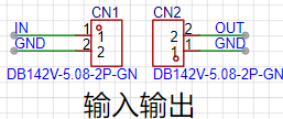
For the power supply circuit, we use a DC connector, the same as the official one. However, I added terminal blocks and Type-C input/output to measure the voltage and current of the Type-C connector and the terminal blocks. For the

Type-C input/
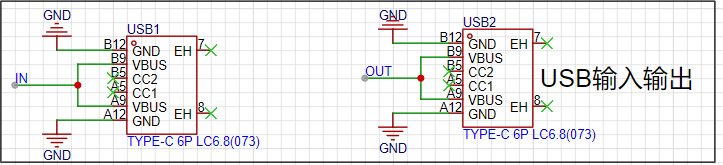
output terminal blocks and
LDO (Low Dropout Linear Regulator) selection, this project uses an LDO as the power supply. Considering that most voltmeter products are used in industrial scenarios with 24V or 36V power supplies, this project selected the SE8550K2, which has a maximum input voltage of up to 40V. The main reason for not using a DC-DC buck converter to handle the large voltage drop is to avoid introducing DC-DC ripple interference during the design process; a secondary reason is to reduce project costs.
2. MCU Selection
: Thanks to JLCPCB for the selection; the Diwenxing MCU was purchased for 1 yuan, and it was a replica.
The CW32's key advantages in this project include
: Wide operating temperature range: -40~105℃;
Wide operating voltage: 1.65V~5.5V (STM32 only supports 3.3V systems);
Strong anti-interference: HBM ESD 8KV; All ESD reliability reaches the highest international standard level (STM32 ESD 2KV);
A key focus of this project – Better ADC: 12-bit high-speed ADC, achieving ±1.0LSB INL 11.3ENOB; Multiple Vref reference voltages... (STM32 only supports VDD=Vref);
Stable and reliable eFLASH technology.
3. Voltage Sampling Circuit:
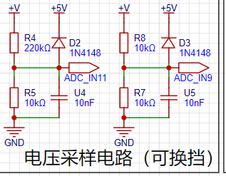
The voltage divider resistors in this project are designed as 220K+10K, therefore the voltage division ratio is 22:1 (ADC_IN11).
The voltage divider resistor selection
is for the maximum measured voltage; for safety reasons, this project uses 30V (the actual maximum display can be 99.9V or 100V).
The ADC reference voltage is 1.5V in this project, and this reference voltage can be configured through the program.
To reduce the power consumption of the sampling circuit, the low-side resistor (R7) is usually chosen as 10K based on experience.
Then, the high-side resistance of the voltage divider resistor can be calculated using the above parameters.
The required voltage division ratio is calculated, i.e., the ADC reference voltage. The input voltage is designed; using known parameters, 1.5V/30V = 0.05 can be calculated.
The high-side resistance is calculated as the low-side resistance/voltage division ratio; using known parameters, 10K/0.05 = 200K can be calculated.
A standard resistor is selected: a resistor slightly higher than the calculated value of 200K is chosen. We usually choose E24 series resistors; therefore, in this project, 220K, which is greater than 200K and closest to the calculated value, is selected.
If, in actual use, the voltage to be measured is lower than 2/3 of the module's design voltage (66V), the voltage divider resistor can be replaced and the program modified to improve measurement accuracy. The following example illustrates this:
Assuming the measured voltage is no higher than 24V and other parameters remain unchanged,
calculations show 1.5V/24V = 0.0625, 10K/0.0625 = 160K. 160K is a standard E24 resistor and can be directly selected, or a higher value 180K can be chosen with some redundancy.
If, in actual use, the voltage to be measured is higher than the module's 99V design voltage, a different resistor can be selected. To achieve a wider voltage measurement range, one can choose to replace the voltage divider resistor or modify the reference voltage. The following example illustrates this:
Assuming the measured voltage is 160V, the solution is to increase the voltage reference to expand the range.
Given that the voltage division ratio of the selected resistor is 0.0145, we can calculate 160V * 0.0145 = 2.32V using the formula. Therefore, we can choose a 2.5V voltage reference to expand the range (increasing the range will reduce accuracy).
Considering the potential fluctuations in the measured power supply, a 10nF filter capacitor is connected in parallel with the low-side voltage divider resistor to improve measurement stability.
Range switching:
In this project, an additional voltage sampling circuit was added. Therefore, we can discuss the significance of range switching for improving measurement accuracy. Multimeters often have multiple range settings for more accurate measurements. By adjusting different ranges, the optimal measurement accuracy of the measured point within the corresponding range can be obtained.
This project requires a combination of hardware and software to achieve this function. When we first use the ADC_IN11 channel mentioned earlier to measure voltages below 30V... If the measured voltage is within 0~3V, use the ADC_IN9 channel for measurement. At this time, due to the reduced voltage division ratio, the measurement accuracy is greatly improved. There are many ways to implement gear shifting, and the development board design provides more design possibilities.
4. Current sampling circuit:

The official design specifies a sampling current of 3A, and the selected sampling resistor (R0) is 100mΩ. I directly replaced it with a 2W resistor, which will have a larger measurable range.
5. Digital tube display:
I used a 0.36-inch digital tube that I had already purchased, which is cheaper. 5 for 2 yuan.

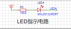
6. LED indicator
: Power-on light ,

program verification light.
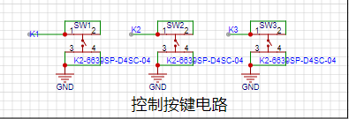
7. Button circuit design:
I used an existing surface-mount button to save money.
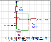
8. TL431 circuit design for voltage measurement calibration:
They tell us to do experiments, but we didn't! ~~~
9. 3D shell: I didn't post pictures because it failed.
For replication, please choose the official project; there is a link to the official project at the top of the article, which can be modified based on the project. There
are too many experts here; I don't expect to win, but improving my own open-source project is a way to learn again and deepen my understanding.
Thank you, I'm leaving.


 京公网安备 11010802033920号

 MX1N985A-1E3


