Below are three ready-to-use systems: Debian, Android, and BuildRoot. BuildRoot includes a complete QT5 library. Baidu Cloud: https://pan.baidu.com/s/1Z9D42gjeBm8wQCB7Bz7hpA?pwd=moyi (Extraction code: moyi)
China Telecom Cloud: https://cloud.189.cn/t/fQJjym2Eriqu (Access code: 4keg)
Quark Cloud: https://pan.quark.cn/s/0d0fa9801285 (Extraction code: chvS)
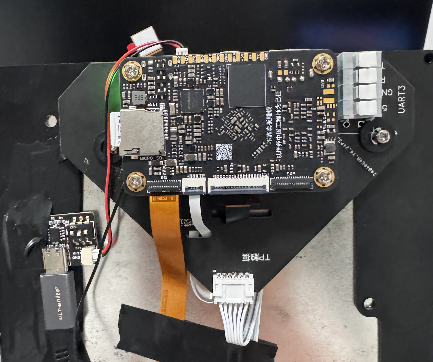
Only the UART3 serial port is exposed for microcontroller communication
to meet coupon printing size requirements.

IMG_0385.MOV
PDF_Taishanpai Jingshang 10.1-inch CNC Adapter Mounting Board.zip
Altium_Taishanpai Jingshang 10.1-inch CNC Adapter Mounting Board.zip
PADS_Taishanpai Jingshang 10.1-inch CNC Adapter Mounting Board.zip
BOM_Taishanpai Jingshang 10.1-inch CNC Adapter Mounting Board.xlsx
95239
Taishanpai screen adapter board
Taishanpai - 3-inch MIPI Touch Screen Adapter Board
3-inch MIPI Touchscreen Porting:
1. Screen Parameters
:
Connect
the screen
(3 Inch, 40 Pin), MIPI
screen .
Touch
Chip: FT5316
(same as above)
. 2. Modify the Device Tree
: Modify the file [SDK_DIR]/kernel/arch/arm64/boot/dts/rockchip/tspi-rk3566-user-v10.dts, disable HDMI and EDP screens, and enable DSI screen.
// #include "tspi-rk3566-edp-v10.dtsi"
// #include "tspi-rk3566-hdmi-v10.dtsi"
#include "tspi-rk3566-dsi-v10.dtsi" // Enable DSI screen
by modifying the file [SDK_DIR]/kernel/arch/arm64/boot/dts/rockchip/tspi-rk3566-dsi-v10.dts, adding FT5316 touch, and modifying screen parameters
// Add FT5316 touch screen
&i2c1 {
status = "okay";
ft5316@38 {
pinctrl-0 = <&touch_gpio>;
compatible = "focaltech,fts";
reg = 8;
focaltech,max-touch-number = <2>;
// focaltech,display-coords =<0 0 854 480>;
focaltech,irq-gpio = <&gpio1 RK_PA0 IRQ_TYPE_LEVEL_LOW>;
focaltech,reset-gpio = <&gpio1 RK_PA1 GPIO_ACTIVE_HIGH>;
};
};
// dsi screen related changes
&dsi1 {
status = "okay";
};
&dsi1_in_vp0 {
status = "okay";
};
&dsi1_in_vp1 {
status = "disabled";
};
&video_phy1 {
status = "okay";
};
&route_dsi1 {
status = "okay";//wucaicheng mipi okay
connect = <&vp0_out_dsi1>;
};
&dsi1 {
status = "okay";
rockchip,lane-rate = <480>;
dsi1_panel: panel@0 {
status = "okay";
compatible = "simple-panel-dsi";
reset-gpios = <&gpio3 RK_PC1 GPIO_ACTIVE_LOW>;
pinctrl-names = "default";
pinctrl-0 = <&dsi1_rst_gpio>;
reg = <0>;
backlight = <&backlight>;
reset-delay-ms = <200>;
enable-delay-ms = <100>;
prepare-delay-ms = <20>;
unprepare-delay-ms = <20>;
disable-delay-ms = <20>;
init-delay-ms = <120>;
dsi,flags = <(MIPI_DSI_MODE_VIDEO | MIPI_DSI_MODE_VIDEO_BURST |
MIPI_DSI_MODE_LPM | MIPI_DSI_MODE_EOT_PACKET)>;
dsi,format = ;
dsi,lanes = <2>;
panel-init-sequence = [
05 78 01 01
05 78 01 11
39 0A 06 FF 77 01 00 00 13
15 0A 02 EF 08
39 0A 06 FF 77 01 00 00 10
39 0A 03 C0 E9 03
39 0A 03 C1 10 0C
39 0A 03 C2 20 0A
15 0A 02 CC 10
39 0A 11 B0 00 23 2A 0A 0E 03 12 06 06 2A 00 10 0F 2D 34
1F 39 0A 11 B1 00 24 2B 0F 12 07 15 0A 0A 2B 08 13 10 2D 33 1F
39 0A 06 FF 77 01 00 00 11
15 0A 02 B0 4D
15 0A 02 B1 48
15 0A 02 B2 84
15 0A 02 B3 80
15 0A 02 B5 45
15 0A 02 B7 85
15 0A 02 B8 33
15 0A 02 C1 78
15 0A 02 C2 78
15 0A 02 D0 88
39 0A 04 E0 00 00 02
39 0A 0C E1 06 A0 08 A0 05 A0 07 A0 00 44 44
39 0A 0D E2 30 30 44 44 6E A0 00 00 6E A0 00 00
39 0A 05 E3 00 00 33 33
39 0A 03 E4 44 44
39 0A 11 E5 0D 69 0A A0 0F 6B 0A A0 09 65 0A A0 0B 67 0A A0
39 0A 05 E6 00 00 33 33
39 0A 03 E7 44 44
39 0A 11 E8 0C 68 0A A0 0E 6A 0A A0 08 64 0A A0 0A 66 0A A0
39 0A 03 E9 36 00
39 0A 08 EB 00 01 E4 E4 44 88 40
39 0A 11 ED FF 45 67 FA 01 2B CF FF FF FC B2 10 AF 76 54 FF
39 0A 07 EF 10 0D 04 08 3F 1F
05 78 01 11
15 0A 02 3A 55
05 14 01 29
];
panel-exit-sequence = [
05 00 01 28
05 00 01 10
];
disp_timings1: display-timings {
native-mode = <&dsi1_timing0>;
dsi1_timing0: timing0 {
clock-frequency = <33500000>;
hactive = <480>;
vactive = <854>;
hfront-porch = <8>;
hsync-len = <2>;
hback-porch = <43>;
vfront-porch = <4>;
vsync-len = <10>;
vback-porch = <42>;
hsync-active = <0>;
vsync-active = <0>;
de-active = <0>;
pixelclk-active = <1>;
swap-rb = <0>;
swap-rg = <0>;
swap-gb = <0>;
};
};
ports {
#address-cells = <1>;
#size-cells = <0>;
port@0 {
reg = <0>;
panel_in_dsi1:endpoint {
remote-endpoint = <&dsi1_out_panel>;
};
};
};
};
ports {
#address-cells = <1>;
#size-cells = <0>;
port@1 {
reg = <1>;
dsi1_out_panel: endpoint {
remote-endpoint = <&panel_in_dsi1>;
};
};
};
};
3. Modify the kernel.
Focaltech touchscreen support is enabled by default in the kernel. You can check if it's enabled in menuconfig. After confirming it's enabled, modify the following code.
Unlike other touchscreens that specify screen size in the device tree, this needs to be changed in the header file. It's a bit tricky.
After completing all steps, compile and flash the program.
// Modify /kernel/drivers/input/touchscreen/focaltech_touch/focaltech_core.h
// Modify this to the screen size
#define FTS_X_MAX_DISPLAY_DEFAULT 480
#define FTS_Y_MAX_DISPLAY_DEFAULT 854
// Modify the /kernel/drivers/input/touchscreen/focaltech_touch/focaltech_core.c file
// If you don't modify the following code, the x-axis touch is reversed. Around lines 658 and 735, change it to 480-events[i].x, as follows:
// Around line 658
#if 1
input_report_abs(data->input_dev, ABS_MT_POSITION_X, 480-events[i].x);
input_report_abs(data->input_dev, ABS_MT_POSITION_Y, events[i].y);
// near line 735
input_report_abs(data->input_dev, ABS_MT_POSITION_X, 480-events[i].x);
input_report_abs(data->input_dev, ABS_MT_POSITION_Y, events[i].y);
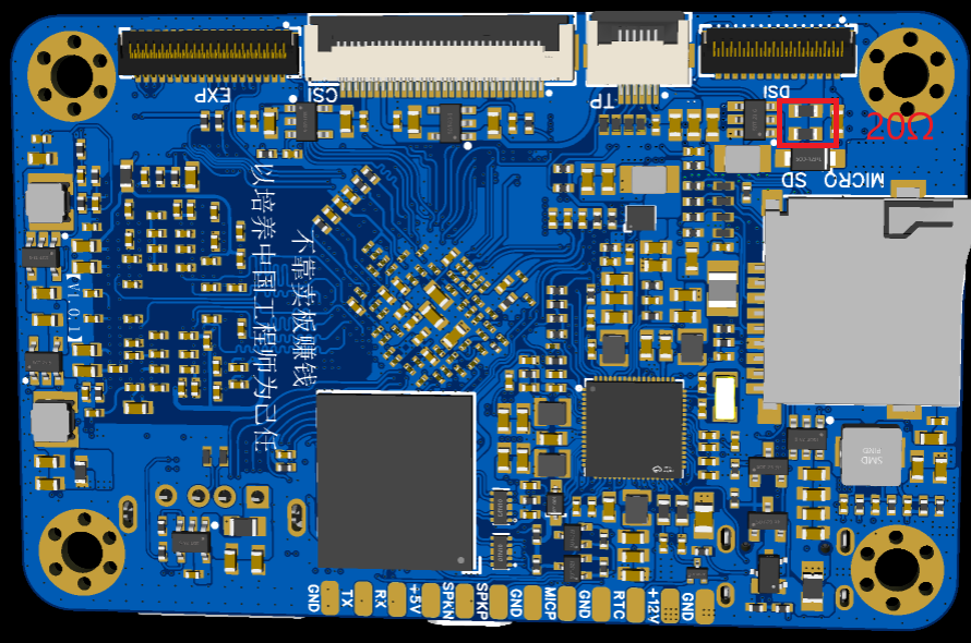
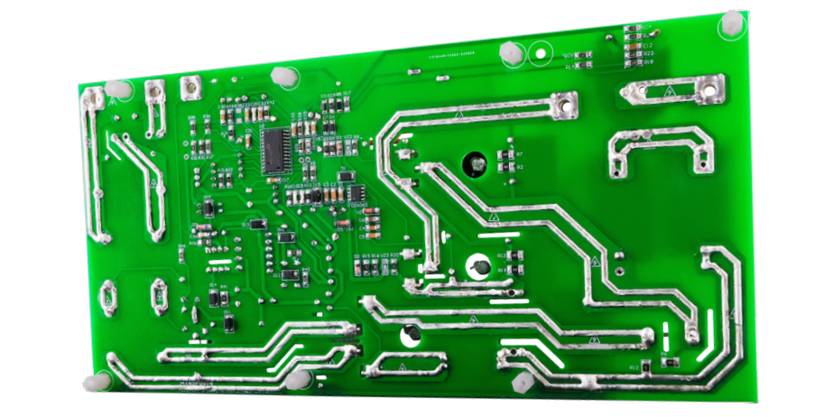
4. Modify the backlight resistor
The screen backlight requires a current of 20mA, so I=0.2V/R, which is acceptable for R=10Ω. Two resistors with R=20Ω can be connected in parallel. Modify the two resistors in the red area of the figure below. There is a lot of room for modification, and it is not difficult to solder with a soldering iron.
efec37a11637aefdf606df659a94ef61.mp4
PDF_Taishanpai Screen Adapter Board.zip
Altium_Taishanpai Screen Adapter Board.zip
PADS_Taishanpai Screen Adapter Board.zip
BOM_Taishanpai Screen Adapter Board.xlsx
95240
PD fast charging decoy module with 5V step-down
USB PD protocol fast charging decoy/power receiving module capable of simultaneously outputting 20V and 5V.
Please do not place an order directly using the BOM (Bill of Materials)! Some components only use their packages; please refer to the schematic diagram for specific parameters!
Principle:
The CH224K protocol chip handles USB-C communication, providing 20V. The LM2596-5.0 step-down voltage is used to 5V. Output via terminal blocks.
PDF_PD Fast Charging Deception Module with 5V Step-Down Voltage.zip
Altium_PD Fast Charging Deception Module with 5V Step-Down.zip
PADS_PD Fast Charging Decoy Module with 5V Step-Down.zip
BOM_PD Fast Charging Deception Module with 5V Step-Down.xlsx
95241
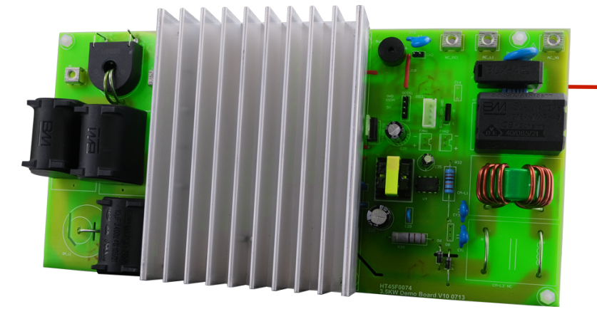
HT45F0074A Half-bridge Induction Cooker
3500W half-bridge induction cooker using HT45F0074A dedicated chip
My induction cooker at home frequently blows its tubes, burning out a bunch of components. So I thought I'd experiment with a half-bridge design. After researching, I found Holtek's solution to be simple, clear, and with complete documentation. Therefore, I'm going to replicate it according to the official documentation to see how it performs. This 3500W half-bridge induction cooker uses the HT45F0074A dedicated chip. The schematic and PCB layout are from Holtek Semiconductor (China) Co., Ltd.'s official demo materials. Those interested can download the relevant BOM, schematic, PCB layout, source code, and other files from their official website.
BOM-HT45F0074爵筿合膌莱ノよ-陪ボ北狾-V01.xls
BOM-HT45F0074Juejunhequinlaiノよ-筿方 recommended狾-V01.xls
BOM-HT45F0074爵筿合膌莱ノよ-陪ボ北狾-V01.pdf
BOM-HT45F0074Jueyonghequinlaiノよ-筿方 recommended狾-V01.pdf
PDF_HT45F0074A Half-Bridge Induction Cooker.zip
Altium_HT45F0074A Half-Bridge Induction Cooker.zip
PADS_HT45F0074A Half-Bridge Induction Cooker.zip
BOM_HT45F0074A Half-bridge Induction Cooker.xlsx
95242
PD decoy
The CH224K chip is used to extract 5V/12V/15V/20V for use by other devices. The PCB is small and easy to carry.
This device utilizes the CH224K chip to extract 5V/12V/15V/20V for use by other devices. The PCB is compact and portable.
It can only be used with chargers and power banks that support the PD protocol.
PDF_PD Deception.zip
Altium_PD Deception.zip
PADS_PD Deception Tool.zip
BOM_PD Deception.xlsx
95243
ESP32 Relay Control Board
Based on the ESP32-WORK-32E as the main controller, with 9 relays, a power supply range of 5-24V, and all functions have been verified.
Based on the ESP32-WORK-32E as the main controller, with 9 relays and a power supply range of 5-24V, all functions have been verified, and the working stability needs to be tested.
3e0d3cea4ac6ea3ac966e3efbf1c4586.mp4
2d07fa401b82afc9d58fc2ec5a1e6d9a.mp4
test.py
PDF_ESP32 Relay Control Board.zip
Altium_ESP32 Relay Control Board.zip
PADS_ESP32 Relay Control Board.zip
BOM_ESP32 Relay Control Board.xlsx
95244
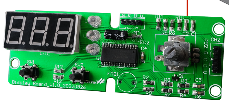
High-power AC voltage regulator (verified, but not perfect)
Power regulator
designed for purely resistive heating appliances such as electric blankets, electric ovens, electric hot pots, and electric ceramic stoves. Maximum power: 2500W.
Verified power: 1500W.
Please do not order the BOM directly! Some components only use their packages; please refer to the schematic diagram for specific parameters!
Principle:
The LM358 operational amplifier generates a low-frequency square wave oscillation with a continuously adjustable duty cycle of 0-100%, controlling the conduction and cutoff of the thyristor. When it is not necessary to reduce the power of the appliance, simply turn the knob with the switch all the way to close the relay, short-circuiting the thyristor.
Function:
Insert the rice cooker cord into the triangular connector, insert the appliance into the 3-pin 220V output interface, and turn the knob to adjust the appliance's power. A row of LEDs provides a semi-quantitative indication of the current power. When the last LED lights up, it indicates that the relay is engaged, and the appliance will be directly connected to the 220V AC mains without any other circuitry.
Imperfections:
1. The 24V to 5V conversion section in this circuit cannot work stably. It is recommended to use the most common LM2596 module from Taobao to replace this part of the circuit. The 3D casing has a reserved position for this module, located on the left side of the circuit board, requiring a jumper wire connection.
2. The thyristor has significant power dissipation and requires fan cooling. The 3D casing has pre-drilled mounting positions and screw holes for the fan, and the PCB also has corresponding fan power supply headers. Please use a 2.5cm*2.5cm 5V small fan.
Precautions:
1. The input and output of this circuit are not isolated; please pay attention to electrical safety.
2. I used this circuit to power an old-fashioned 1500W electric hot pot, and it has been working for over a year without any problems. However, I haven't tried it with higher-power appliances.
Cover plate.STL
Shell.STL
volt_4.JPG
volt_5.JPG
volt_1.JPG
PDF_High-Power AC Voltage Regulator (Verified, Not Perfect).zip
Altium_High-Power AC Voltage Regulator (Verified, Not Perfect).zip
PADS_High Power AC Voltage Regulator (Verified, Not Perfect).zip
BOM_High-Power AC Voltage Regulator (Verified, Not Perfect).xlsx
95245
electronic


 京公网安备 11010802033920号

 171-005-25P-.172BLMH


