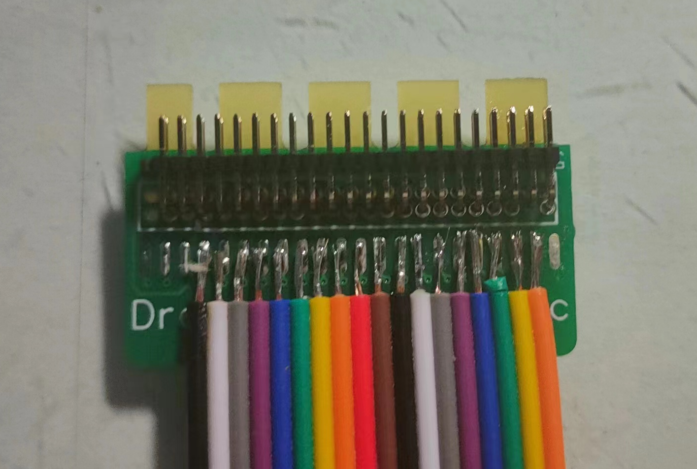
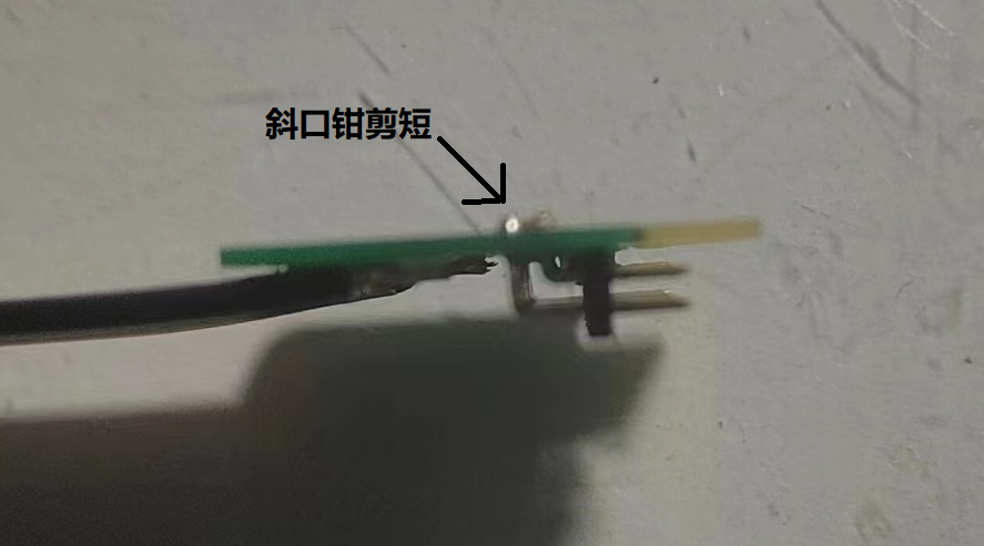
Choose a thickness of 0.8mm. Use 1.27mm double-row bent pin headers. For length, I used the 3.0mm long black plastic side, which is more than enough; there's no need to go any longer. The cost is 1.9 yuan for 2 x 40pin headers. Use standard rainbow DuPont wire; the cost is 2 yuan per 40pin. You'll also need 16 resistors in 0603 packages. The original design used a 100kΩ resistor plus an unknown capacitance capacitor for high-frequency compensation. However, since the DSlogic's input capacitor is approximately 3.9pF, I recommend using 200Ω resistors instead of 100kΩ. Shorting these is possible but not recommended (if shorted, it's only suggested for measuring signals within 0-3.3V). Refer to the pictures for the rest; I believe you'll all be able to handle it without any problems.
Hardware:
Digital tube display;

Button control;

Power input:

12V input is filtered twice before being sent to a step-down chip to 5V, outputting 5V and lighting LED2.
Other parts are the same as in the example program and will not be repeated here.
All components are surface-mount to reduce size.
Software:
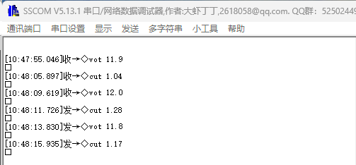
The official example program is used directly, but because the digital tube is damaged, serial port data output is used.
TOP_V2.stl
BOT_V2.stl
CW32.rar
PDF_cw32 current voltmeter.zip
Altium_cw32 current voltmeter.zip
PADS_cw32 current voltmeter.zip
BOM_cw32 current voltmeter.xlsx
93043
Innolux HJ070NA-13A screen power supply board and LVDS level conversion circuit
This design provides the voltages required to drive the LCD screen, such as AVDDVLEDVGHVGL, and includes a level conversion circuit from TMDS33 to LVDS15.
Version Notes:
Rev. 1
uses Xi'an Aerospace Minxin's BOOST chip MT3608 to provide VGH, VLED, and AVDD.
It uses Xinzhou Technology's SCT2450 to provide negative voltage VGL.
The VCOM correction circuit is provided by the screen datasheet.
A resistor divider scheme implemented by a foreign developer was used to convert TMDS33 to LVDS15 (see TMDS33 to LVDS - element14 Community).
Design flaws: The 1.5V voltage did not exceed the minimum voltage drop of the LED, failing to light the corresponding indicator light. This was not considered during the design process . Design flaws:
The orientation of the FPC was not taken into account, preventing the board from being mounted on the back of the screen as expected.
Not yet implemented: The power-on sequence required by the LCD screen is temporarily simulated manually using a switch.
Rev. 2
adds Texas Instruments' LM3880 for timing control, selecting a sub-model with a 2ms delay.
A small solid-state register is used to enable VGH and VGL.
The 1.5V indicator light has been removed
. 3.
Texas Instruments' TPS65150 was used to provide VGH, VGL, AVDD, and VCOM.
All voltage divider resistors used to determine the output voltage reference were replaced with variable resistors to adapt to other similar screens.
Since the TPS65150 has delay control, the LM3880 was omitted.
A socket layout adapted to the Atomic S6 core board was designed, which to some extent solved the interference caused by using DuPont wires during transmission.
LOG
2024.7.24: Rev.1 design completed.
2024.7.29: Rev.1 was verified, and the color bar driver based on Spartan6SLX16 was completed.
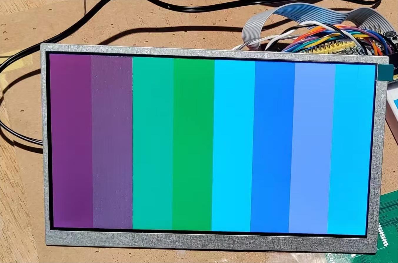
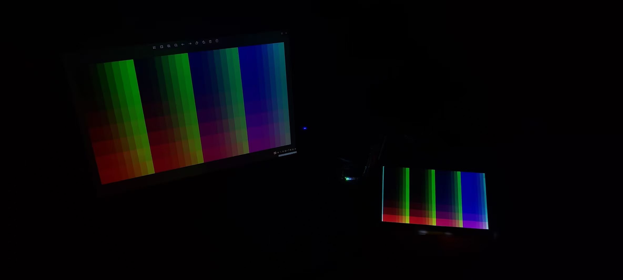
2024.7.30: It was found that colors containing red and green primary colors showed a large deviation when displayed on the LCD, accompanied by relatively dense speckles, while other colors displayed normally. A connection between the two LVDS signal channels was suspected. The connection problem was corrected by resoldering, but the above colors still could not be displayed normally (leaning towards green), and the speckles were still not resolved.
August 1, 2024: It was discovered that a 12-pixel display area on the far left of the screen should actually be on the far right. After attempts, it was found that this display misalignment could not be eliminated by modifying the timing or clock. The cause of this phenomenon is currently unknown. It is planned to discard the 12 pixels on each side in future use of this screen and use a 1000x600 resolution.

August 1, 2024: The serial-to-parallel conversion module was rewritten using the oserders2 primitives provided by Xilinx. The color deviation disappeared, but the speckling remains. Using the custom-written serial-to-parallel conversion module causes a "color mixing phenomenon" (as shown in the figure, the expected display is a color range from #F800 to #8800, which is significantly different from the actual displayed color). It is currently speculated that this is caused by the serial-to-parallel conversion module synchronously reading on the rising edge of the pixel, actually displaying an indeterminate state. The serial-to-parallel conversion module driven by the oserders2 primitives, due to the 90-degree amplitude lag between the serial-to-parallel conversion sampling and the pixel, displays correctly. The program is attached.

August 2, 2024: VGL was mistakenly connected before DVDD, and then VGH was connected, causing the screen to burn out (VLED wasn't connected at the time, but the screen clearly turned white and then wouldn't light up again).
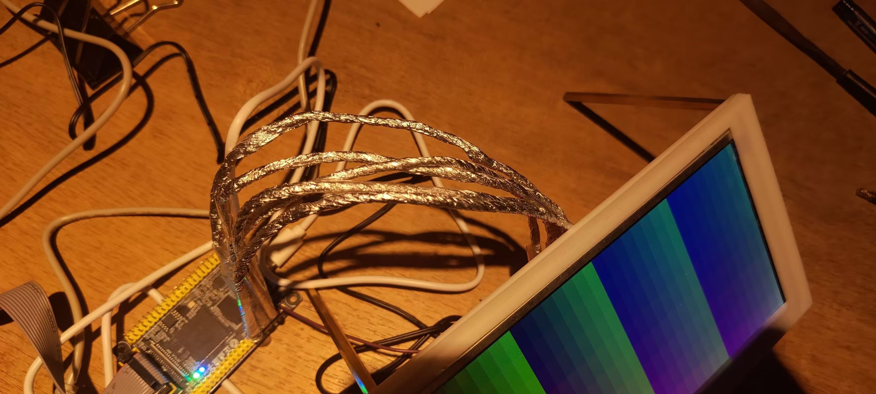
August 5, 2024: Inspired by a foreign developer (LCD panel + FPGA with an HDMI sink = External Display - element14 Community), I wrapped the twisted-pair cable with aluminum foil, temporarily solving the interference problem during signal transmission; the pitting almost disappeared.
August 8, 2024: Completed the schematic design for Rev.2.
August 10, 2024: During testing, I tried moving the transmission line and found that the discoloration and pitting reappeared. I tried restoring the transmission line to its original position, but it didn't improve the situation, suggesting a possible contact issue. I temporarily rejected the solution requiring connecting cables and decided to design an expansion board that can directly connect to the FPGA.
August 14, 2024: Completed the design for Rev.3.
LVDS_test_oserder2.zip
PDF_Innolux HJ070NA-13A Screen Power Supply Board and LVDS Level Conversion Circuit.zip
Altium_Innolux HJ070NA-13A Screen Power Supply Board and LVDS Level Conversion Circuit.zip
PADS_Innolux HJ070NA-13A Screen Power Supply Board and LVDS Level Conversion Circuit.zip
BOM_Innolux HJ070NA-13A Screen Power Supply Board and LVDS Level Conversion Circuit.xlsx
93044
LCSC voltage and current meters
This design is for an ammeter and voltmeter, and uses an OLED to display the data.
1. Introduction:
This design is a current and current meter, using an OLED display for data.
2. Function Introduction:
The digital current and current meter combines ADC technology with circuit measurement principles, accurately converting analog voltage and current signals into digital displays for easy reading and analysis by electronic engineers. This device not only improves the accuracy and efficiency of circuit measurements but also helps engineers better understand circuit behavior, making it a powerful tool for electronic design and troubleshooting, playing a significant supporting role in the work of electronic engineers. In product applications, the digital current and current meter ensures the accuracy and safety of circuit design, while also providing strong support for product quality control and subsequent maintenance.
3. Physical Image

4. Software and Hardware Description:
The software and hardware components of this design are referenced from the organizer's training camp software and hardware, with some innovations. Due to my limited expertise, I will not elaborate on the software and hardware aspects further.
For details, please see the link: CW32 Digital Current and Current Meter Training Camp Project Tutorial Document | LCSC Development Board Technical Document Center (lckfb.com)
5. Demonstration Video and Other Files
: See attached files.
WeChat_20240819162257.mp4
WeChat_20240819162303.mp4
Gerber_PCB1_2024-08-19.zip
3DShell_PCB1.zip
Ammeter and voltmeter.xlsx
Panel_Panel_1_2024-08-19.epanm
Final program.zip
PDF_LCSC Voltage and Current Meters.zip
Altium_LCSC Voltage and Current Meter.zip
PADS_LCSC Voltage and Current Meters.zip
BOM_LCSC Voltage and Current Meter.xlsx
93045
CW32 Voltage and Current Meter
LCSC GeoStar CW32 Digital Voltage and Current Meter
Voltmeters and ammeters are indispensable tools in electronic design, but benchtop digital multimeters are bulky and expensive. Therefore, I designed a simple digital voltmeter and ammeter based on the LCSC CW32 microcontroller.
It adopts a core board plus expansion board design concept, using plug-in components to simplify learning and allow for deeper exploration.
The core board uses the domestically produced Wuhan Xinyuan Semiconductor CW32 as the main controller, while also being compatible with other similar development boards; however, the CW32 has advantages.
The project is highly integrated and practical, and after completion, it can be used as a desktop instrument.
#LCSC Training Camp# CW32 Voltage and Current Meter.mp4
BOM_CW32 Voltage and Current Meter.xlsx
PDF_CW32 Voltage and Current Meter.zip
Altium_CW32 voltage and current meter.zip
PADS_CW32 Voltage and Current Meter.zip
93046
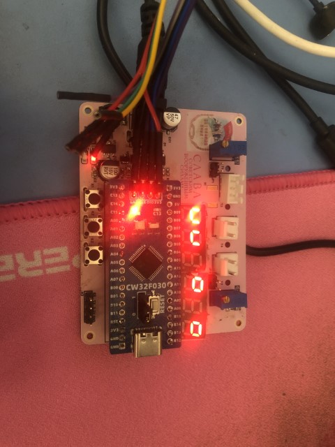
Voltmeter and Ammeter
null
I. Team Introduction
: This is an individual project involving replication.
II. Hardware Circuit Composition
: Utilizing the CW32F030 development board and learning from LCSC's extended version.
III. Program:
Utilizing the high-precision ADC sampling in the CW32 and displaying the data on a digital tube .
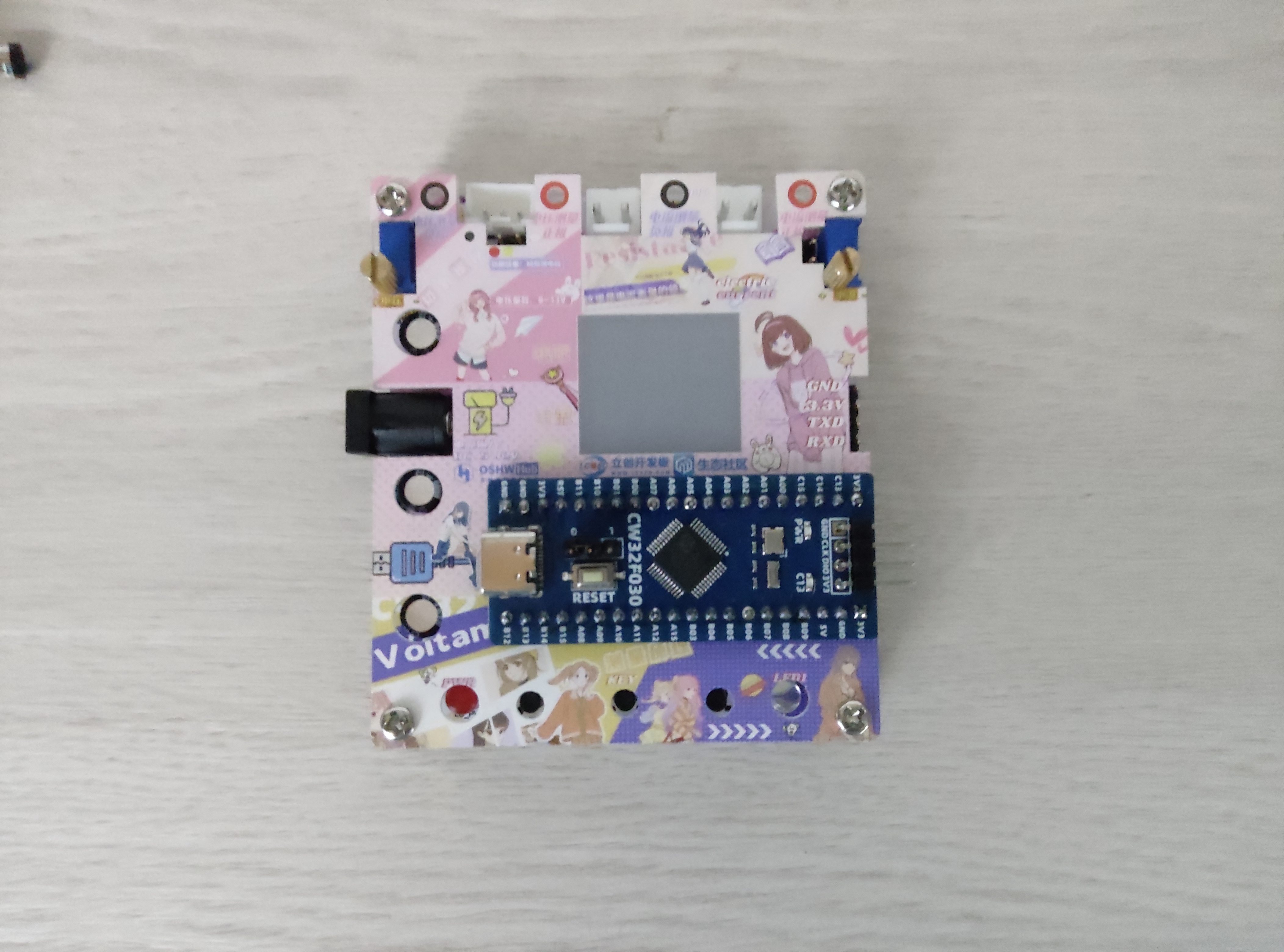
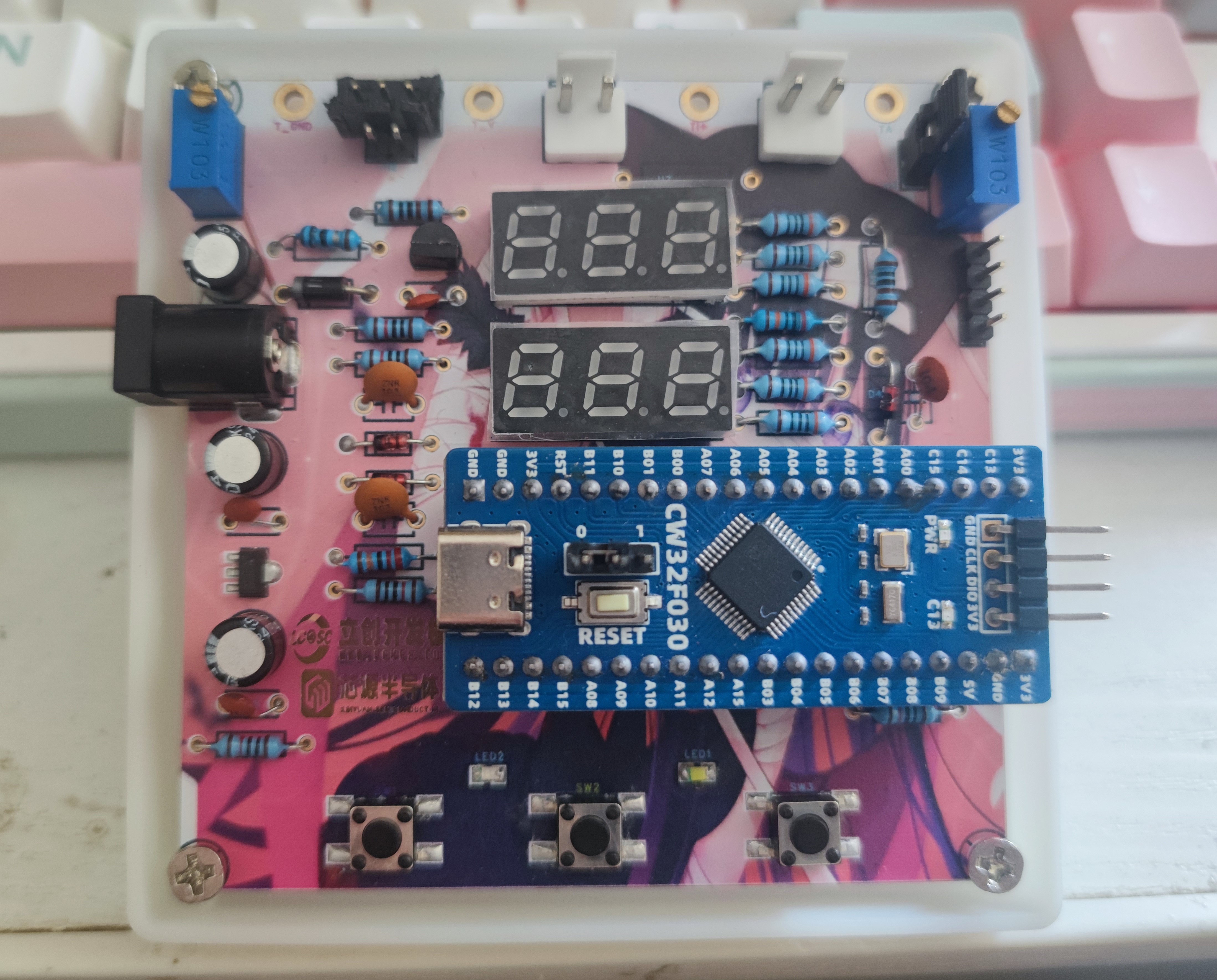
IV. Physical
Demonstration: Includes photos of the actual product with captions.
V. Demonstration Video
Attachment
VID_20240819_155843.mp4
PDF_Voltage and Current Meters.zip
Altium_voltmeter_currentmeter.zip
PADS_Voltage and Current Meter.zip
BOM_Voltage and Current Meter.xlsx
93047
mach3 interface board
The old MACH3 parallel port interface board retains a manual board interface.
There probably aren't many parallel port MACH3 motherboards left now; they're from many years ago. Parallel ports were on motherboards around ten years ago. Gigabyte B85 motherboards (with CPUs like the i5 4570 and 1150) have parallel and serial ports. I have several motherboards with parallel ports (B85, J1900...) and want to revive my old CNC engraving machine.
Using the 74ACT245 is better for the U201 and U202 because its input level is compatible with TTL input (high level minimum 2.0V), suitable for laptop parallel ports (some are 3.3V). Of course, such laptops are rare now.
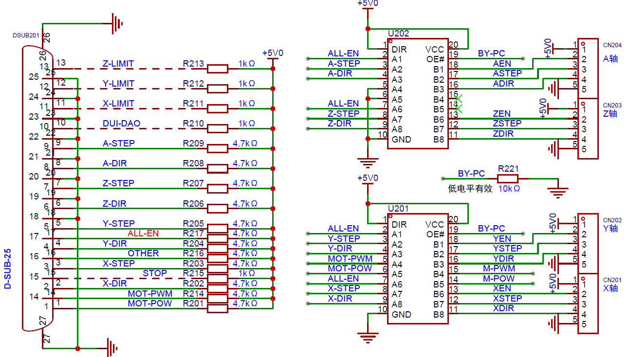
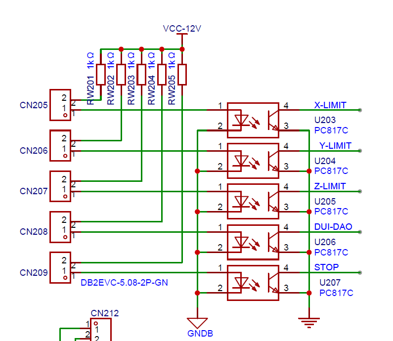
Below are the limit switch interface, tool setting interface, and emergency stop interface.
This is PWM to 10V to control the spindle motor speed.

Below is the manual control interface; this part doesn't need to be soldered. The switch is on the manual control side; pressing the switch manually switches to manual mode. If the switch isn't pressed, it doesn't affect the parallel port interface board.

Below is the motor rotation switch, which is basically a relay.

It seems that because it's a professional version, the PCB/SCH is combined.
Some of the BOMs are for components I have on hand.
PDF_mach3 Interface Board.zip
Altium_mach3 Interface Board.zip
PADS_mach3 Interface Board.zip
BOM_mach3 Interface Board.xlsx
93048
electronic


 京公网安备 11010802033920号

 MV1N5237A-1


