1. Project Function Introduction:
This project adopts a core board plus expansion board design concept, using plug-in components to simplify learning and deepen exploration.
The core board uses the domestic Wuhan Xinyuan Semiconductor CW32 as the main controller, while also being compatible with other similar development boards; however, the CW32 has advantages.
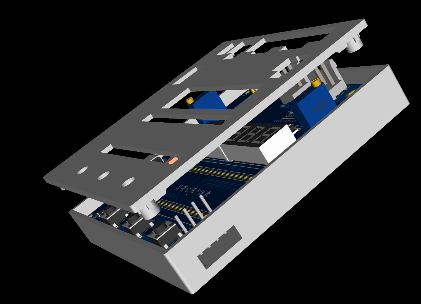
The project is highly comprehensive and practical, and can be used as a desktop instrument after completion.
The project offers abundant learning materials, including circuit design tutorials, PCB design, code programming learning, and training for engineers' debugging skills.
2. Project Attributes:
This project is an improved version of an official case study from a training camp jointly organized by JLCPCB and Wuhan Xinyuan Semiconductor. This version is being publicly released for the first time.
This project won an award at the school and is a good open-source project.
3. Open Source License:
GPL 3.0.
This is the GNU General Public License. If a product under the GPL license is used in a project, then the project must also use the GPL license, meaning it must be open source and free.
The GPL's premise is the open-source and free use of code, and the open-source and free use of referenced, modified, and derived code, but it does not allow modified and derived code to be released and sold as closed-source commercial software.
The most prominent features of the GPL are "viral dissemination" and "no closed-source commercial distribution." Linux, which we are familiar with, uses the GPL license.
The basic principles of GPL 3.0
are: 1. You can use, copy, modify, and distribute protected programs for free, but you must provide the source code when distributing.
2. You can charge fees. For example, you can charge for the distribution of object code or source code, and for software maintenance (mainly providing technical support, hereinafter referred to as "maintenance"); but you cannot charge licensing fees, royalties, patent licensing fees, or authorization fees.
3. All contributors to GPL programs automatically provide free patent licenses and promise not to sue others for patent infringement (provided you comply with the GPL).
4. GPL programs allow others to crack them. If used on consumer hardware, you must allow people to modify and install programs.
4. Hardware Components
1. Voltage Sampling Circuit
This project uses a voltage divider circuit to achieve high voltage acquisition. The design is to acquire a voltage of 100V, and the current configuration acquires a voltage of 0-30V. This project uses a 220K+10K voltage divider resistor, resulting in a voltage division ratio of 22:1 (ADC_IN11).

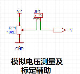
This project also includes circuits for simulating voltage measurement, measurement calibration, and measurement calibration assistance.
2. Current Sampling Circuit :
This project uses a low-side current sampling circuit for current detection. The low-side of the sampling circuit shares a common ground with the development board's meter interface.
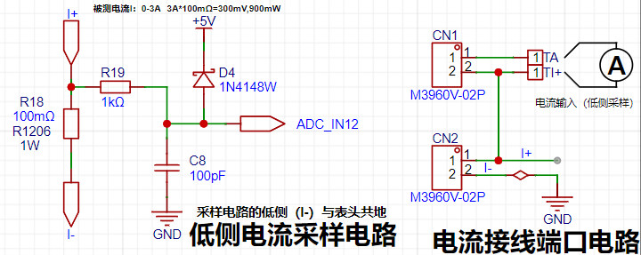
The designed sampling current is 3A, and the selected sampling resistor (R0) is 100mΩ.
The following aspects should be considered when selecting a sampling resistor:
1. The maximum value of the pre-designed measurement current, which is 3A in this project.
2. The voltage difference caused by the current sensing resistor; it is generally not recommended to exceed 0.5V
. 3. The power consumption of the current sensing resistor; a suitable package should be selected based on this parameter. Considering the power consumption (temperature) issue at high current, this project selected a 1W packaged 1206 resistor. However, considering thermal resistance, replicators can replace it with a 3W packaged resistor in a 2512 or 1812 package.
4. Amplification factor of voltage across the current sensing resistor: No operational amplifier was used in this project, so the amplification factor is 1.
The current sensing resistor value can then be calculated using the above parameters:
1. Since no amplifier circuit was used, a larger sampling resistor was needed to obtain a higher measured voltage for measurement.
2. Considering that a larger resistor would result in a larger voltage drop and higher power consumption, an unlimited selection of a larger resistor was not possible.
3. A 1W package resistor was used in this project, corresponding to a power consumption of 1W.
Based on the above data, a 100mΩ current sensing resistor was selected. According to the formula, 3A * 100mΩ = 300mV, 900mW,
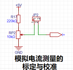
is used for simulating current measurement, measurement calibration, and auxiliary circuitry for measurement calibration.
3. Digital tube display circuit:

This project used two 0.28-inch three-digit common cathode digital tubes as display devices. Compared to a display screen, digital tubes have better visibility in complex environments. A smaller current-limiting resistor can be used to achieve higher brightness based on the actual usage environment. Furthermore, digital tubes have better mechanical properties and are not as easily damaged by external forces as display screens. In industrial and other applications requiring stability and reliability, it is widely used. From a development board learning perspective, it is easier to learn the development related to electronic measurement principles in a more targeted manner.
In this project, after actual testing, the current-limiting resistors (R1~R6) of the digital tube were configured to 300Ω. The corresponding brightness of both red and blue digital tubes has good recognition and the brightness is soft and not dazzling.
3. TL431 circuit design for voltage measurement calibration

This project adds an extra TL431 circuit to provide a 2.5V reference voltage, which can be used to provide an external voltage reference for the chip to calibrate the AD. From a product design perspective, due to the inherent ADC performance advantages of the CW32, this circuit is not necessary.

5. Software part
The software part was designed by JLCPCB and Wuhan Xinyuan Semiconductor. The official tutorial documents have been written in detail, so I will not go into too much detail here. I will describe some key points here, such as the function of the three buttons on the board and how to use them.
Calibration operation method of this experiment
This example uses button operation for calibration. The specific operation method is as follows:
Define 5 working modes, and the K1 key is used to switch the display mode. The K2 key sets the parameter value for the corresponding mode and saves it to FLASH. The K3 key returns to mode 0.
Mode 0: Displays normal voltage and current values (the upper row of the digital tube displays the voltage value *.V or .*V automatically, the lower row displays the current value _.**A).
Mode 1: 5V voltage calibration setting. The upper row of the digital tube displays 5.05. The lower row displays the current voltage value _.V or ._V. In this mode, the multimeter should be set to 5.00V when measuring the measured bit. Pressing the K2 key calibrates the current value to 5V.
Mode 2: 15V voltage calibration setting. The upper row of the digital tube displays 5.15. The lower row displays the current voltage value _.V or ._V. In this mode, the multimeter should be set to 15.0V when measuring the measured bit. Pressing the K2 key calibrates the current value to 15V.
Mode 3: 0.5A current calibration setting. The top row of the digital display shows A.0.5. The bottom row shows the current current value _.**A. Pressing the K2 key sets the current value to 0.5A.
Mode 4: Current 1.5A calibration setting. The top row of the digital display shows A.1.5. The bottom row shows the current current value *.**A. Pressing the K2 key sets the current value to 1.5A.
For software tutorial documents, please click >>>
...
1. This circuit design uses the LCSC Diwenxing development board as the main controller, employing a modular design for learning purposes. It can be purchased from the LCSC development board website for less than 10 yuan per board.
2. This circuit design uses 0.28-inch digital tubes. You can choose the color yourself; 5 digital tubes for 3 yuan on Taobao are much cheaper than a display screen.
3. This circuit uses an 8550LDO with a maximum input voltage of 40V, which is very convenient for VP power supply. In practice, a 5V Type-C interface is used for power supply; the LDO is reserved for VP.
4. Most importantly, this design uses a banana plug similar to a multimeter, allowing for easy connection of the probes. Note! Multimeters use 4mm banana plugs, while this circuit design uses 2mm banana plugs. Please do not buy the wrong one!
5. Attention! This design used JLCPCB color screen printing. You can choose which screen printing method to export. I also designed a 3D casing for this project, which can be printed independently. With a casing, a JLCPCB panel is essential, and yes, I designed a cute panel as well.
6. When ordering JLCPCB acrylic panels, be sure to click "Confirm Production." You MUST click "Confirm Production," otherwise a defective product will be printed. Panel properties can be selected by yourself.
8. Demonstrate your project and record a video for uploading. For
a detailed video explanation, please click >>>>>> Video Explanation


 京公网安备 11010802033920号

 MX26C1000BQI-15


