【Azure Archives】Sensei's Crazy Electric Fan
Bilibili Video:
https://www.bilibili.com/video/BV1uw4m1k7Uo
1. Introduction:
In the sweltering summer, let Sensei bring you coolness!

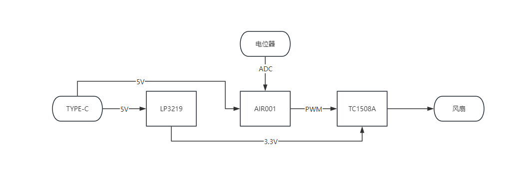
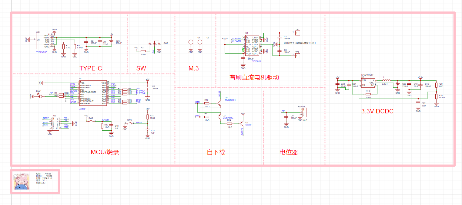
Using a TC1508A as the DC brushed motor driver and a Hezhou AIR001 as the MCU main controller, the 3.3V version uses an LP3219 as the DCDC small fan, which can also be used as an acrylic standee.
The 5V version diagram is shown below. The

3.3V version diagram is shown below.
2. Acrylic Standee
Illustration: Sensei's illustrations are drawn by myself, and the copyright belongs to me.
Self-drawn:
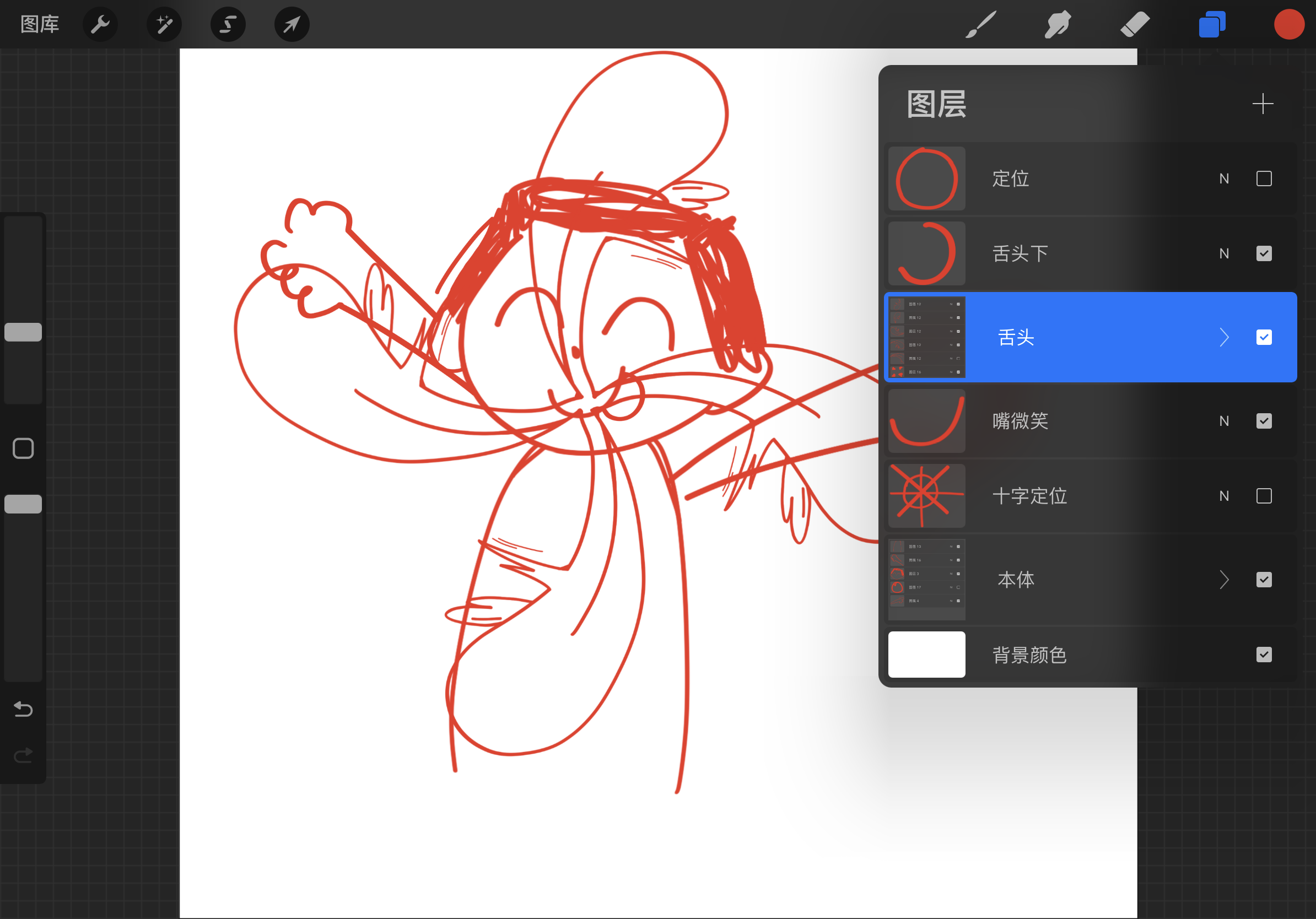
The illustration files can be found in the group files in the discussion group 189480376.
It can be used for personal use, learning, gifts, or freebies. Please do not use it for commercial purposes! 1.
Print the body 20x16cm
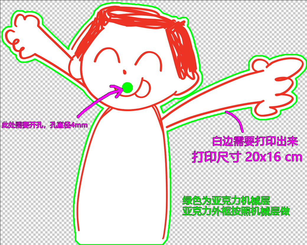
and the tongue 16x16cm. Coated paper is recommended for printing.
![]()
The panel can be printed with PC, but I haven't done it yet, so I don't know how well it will look.


2. Align the structure
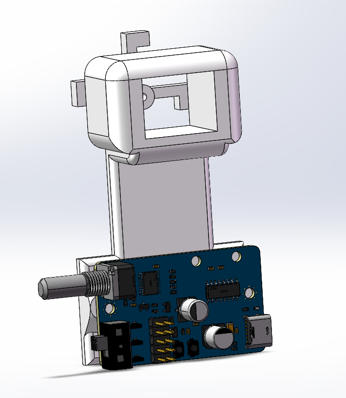

directly with the opening and then glue it on.
3. The circuit
is very simple; you can look it up yourself. I won't go into details.

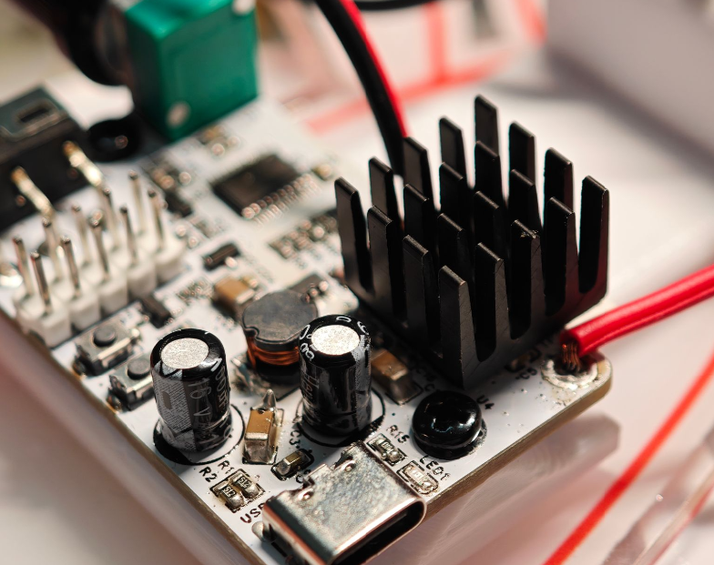
The motor drive generates a lot of heat, so I suggest adding a heatsink. Don't use low-temperature solder .
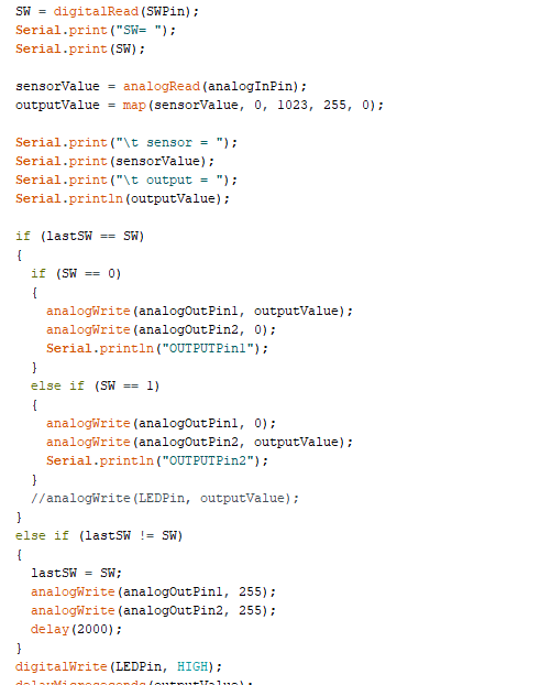
4. The code
is updated based on AnalogInOutSerial.
Install the AIR001 ARDUINO development board environment.
The startup sound is simple; although there's no buzzer, you can use a motor as a buzzer. Give it a PWM signal that's not strong enough to make it turn, and it will vibrate and make a sound.
Then, it checks if the potentiometer is off; if not, it emits an alarm sound.

The rest is a simple loop that reads the potentiometer ADC and outputs the PWM; I won't go into details.
3D.7z
AnalogInOutSerial.zip
PDF_【Azure Archives】sensi Crazy Electric Fan.zip
Altium_【Azure Archives】sensei Crazy Electric Fan.zip
PADS_【Azure Archives】sensei Crazy Electric Fan.zip
BOM_【Azure Archives】Sensei Crazy Electric Fan.xlsx
93573
Easy-to-solder QCC5125 + PCM5102 Bluetooth decoding headphone amplifier
Thanks to Black Cat and the filter capacitor expert for the open source!
Version
1.0 fixed the error of reversed diodes in the power management module schematic. Power module verification completed.
1.1 Fixed some minor bugs. Testing completed, can be used normally.
1.2 Fixed some major bugs. Used a ready-made power management module from Taobao. Testing completed. This is the final version of this project.

Note:
It is not recommended to use solder paste to solder the Bluetooth module, as it is easy to cause solder bridging (
pay attention to solder bridging at the C port). Before powering on, measure whether each power supply is short-circuited to ground
. The opening for the capacitor in the current version seems to be too small. It is recommended to enlarge the hole yourself with a file.
The manufacturer's specifications are in the attachment.
It cannot charge after the switch is turned off. These minor issues will be addressed in a new project later (just kidding).
Design goal:
Supports LDAC encoding HIFI (realistic) Bluetooth decoder, small size of 23*70mm (as you can see, it can be compressed), low soldering difficulty, complete button control
architecture.
Uses QCC5125 ready-made Bluetooth module IIC output, Bluetooth up to LDAC. 96kHz 24bit, USB input 48kHz 16bit (this is a bit of a drawback). After decoding with PCM5102, the output is amplified by LM4881.
The power supply design uses a battery, boosted to 6V by MT3608DCDC, and then regulated by three ME6211LDOs to provide two 3V/3V and 5V channels to power the Bluetooth module, decoder, and headphone amplifier respectively. TP4057 manages charging.
The current version uses a Taobao integrated charging/discharging module.
Note that
I am a complete novice, heavily referencing other engineering designs, and the schematics are patched up. The main design has been verified.
There is limited information on the MT3608; the design referenced is a module from Taobao, and its practicality needs further verification.
Cost calculation:
46 RMB, AL5125 module
5 RMB, Youxin Electronics PCM5102A. The total cost is approximately 80 yuan, including
3 yuan for the LM4881 and 20 yuan
for other components. Further improvements are suggested, such as replacing the DAC with a newer one and a better headphone amplifier (e.g., ES9018 + MAX97220). The THD+N parameters of the LM4881 are indeed not ideal. According to the datasheet, at 32 ohms impedance and 75mW output power, the THD+N is 0.02%, which is not very impressive. Improve charging management by adding independent charging and DC-DC output sections to avoid the current inconvenience of having to keep the device powered on to charge. Modularize the Bluetooth section by adding a separate USB interface to create a modular Bluetooth and USB integrated dock (or even a high-end independent power supply). See the project/ramblings here : https://oshwhub.com/w565670605/qcc3034-lan-ya-5-2-er-fang-_2024-03-24_16-15-24 This project (https://oshwhub.com/xyzdiy/hifi-lan-ya-yin-xiang ) extensively uses 0603 packages to facilitate soldering for someone like me with clumsy hands. A separate small board is used for power management to reduce layout complexity, and an external antenna further simplifies the design. The QCC5125 and QCC3034 module pins should be compatible; refer to the manufacturer's manual for details. The rules for copper plating and forbidden areas in the power module haven't been changed, so there might be minor issues when opening it. You can try modifying it yourself . This is a beginner's attempt; anything missing will be modified later.
SJR-BTM571-v1.0.pdf
LM4881.pdf
PCM5102.pdf
SJR-BTM524_SCH.pdf
SJR-BTM525_SPEC.pdf
PDF_Easy-to-Solder QCC5125 + PCM5102 Bluetooth Decoder Amplifier.zip
Altium_Easy-to-Solder QCC5125 + PCM5102 Bluetooth Decoder Amplifier.zip
PADS_Easy-to-Solder QCC5125+PCM5102 Bluetooth Decoder Headphone Amplifier.zip
93575
STC32G12K128-LQFP64 Minimum System Board
The STC32G12K128-LQFP64 minimum system board features all pins exposed for easy use and module program debugging. It has been verified to successfully light up one LED.
The main controller uses two chip packages: STC32G12K128-QFN64 and LQFP. The appropriate chip can be selected for PCB fabrication and soldering.
It has 64 I/O ports.
An onboard 5V to 3.3V converter provides 5V, GND, and 3.3V outputs for easy power supply to external modules.
The board includes one power LED, one user LED
, two user buttons, one normally closed power switch, and one normally open download/reset button.
A serial port interface is provided.
A Schottky diode is added to the 5V input of the Type-C interface to prevent current reversal.
Hardware USB download is used. Pressing the reset button and then powering on via USB...
d335dcd14c9908ca480fe8d9719df0ff.mp4
IO-LED.hex
stcai-isp-v6.94H.exe
PDF_STC32G12K128-LQFP64 Minimum System Board.zip
Altium_STC32G12K128-LQFP64 Minimum System Board.zip
PADS_STC32G12K128-LQFP64 Minimum System Board.zip
BOM_STC32G12K128-LQFP64 Minimum System Board.xlsx
93576
STC32G12K128 Line-Following Car
The system primarily uses the STC32G12K128-Beta-LQFP64 microcontroller and requires the car to have a line-following function. It utilizes a CH340N download circuit with a TYPE-C port, featuring eight LEDs and four buttons for learning.
1. The racing track is composed of multiple white KT boards covered with black tape. The guide lines are made of 3mm wide black tape, as shown in Figure 1. The participating car models are required to complete the tracking task in the fastest time.
![Image 1.png]

2. Grayscale sensor (the sensor is shown in the attachment)
![WeChat image_20240716132028.jpg]
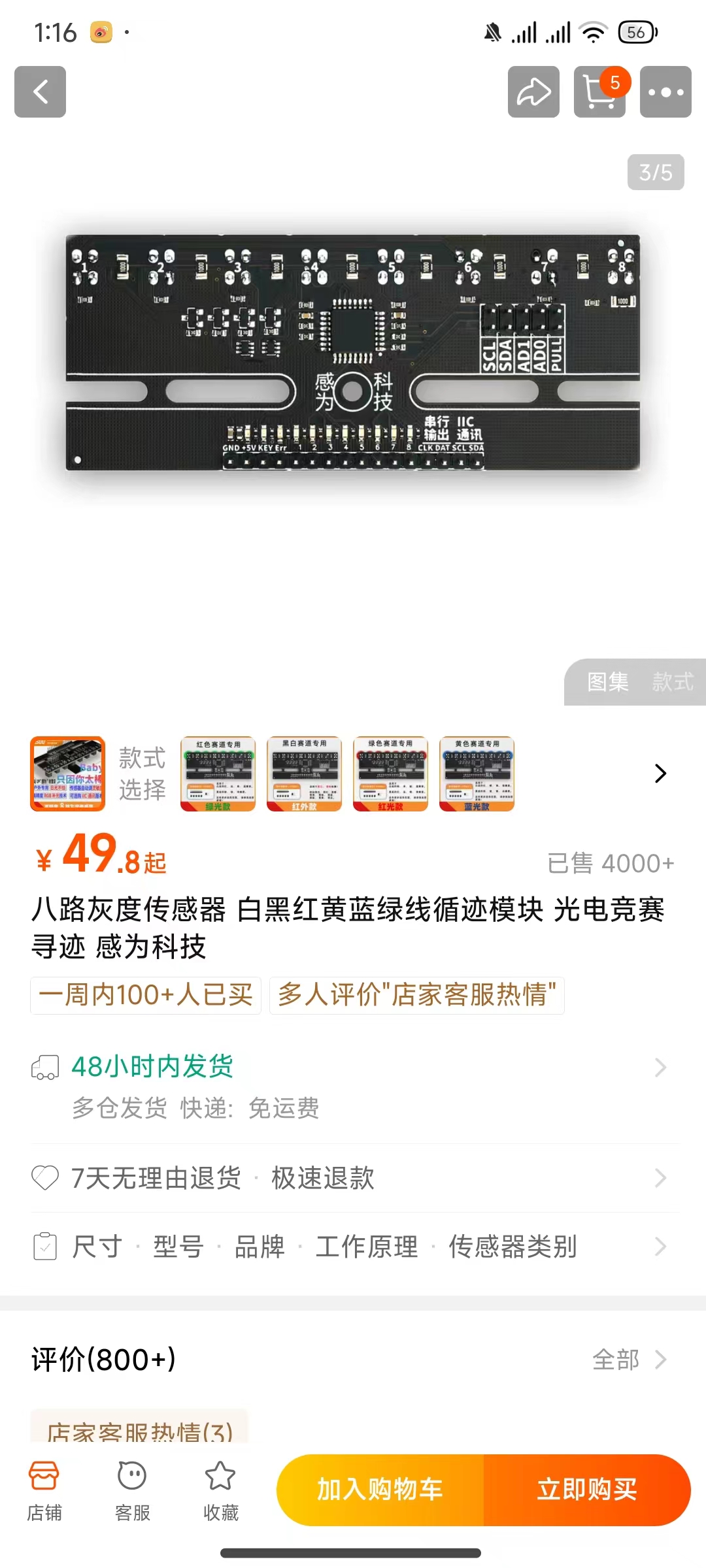
3. The motor uses an N20 geared motor
. 4. A general-purpose two-wheeled chassis is sufficient for the vehicle body.
5. A TFT display screen has been verified.
WeChat_20240716131600.mp4
Car.zip
Complete line-following code.zip
WeChat_20240723195024.mp4
1.8 LCD Display SPI Example Program.zip
Motherboard User Manual.pdf
WeChat_20240723195713.mp4
PDF_STC32G12K128 Line-Following Car.zip
Altium_STC32G12K128 line-following car.zip
PADS_STC32G12K128 Line-Following Car.zip
BOM_STC32G12K128 Line-Following Car.xlsx
93577
Bluetooth voice speaker
This project uses the STC8H8K64U-45I-LQFP32 as the main controller to communicate with the KT1025A via serial port, and can be operated via button control and voice control.
Project Overview:
This project uses the STC8H8K64U-45I-LQFP32 as the main controller for serial communication with the KT1025A, and can be operated via button control and voice control.
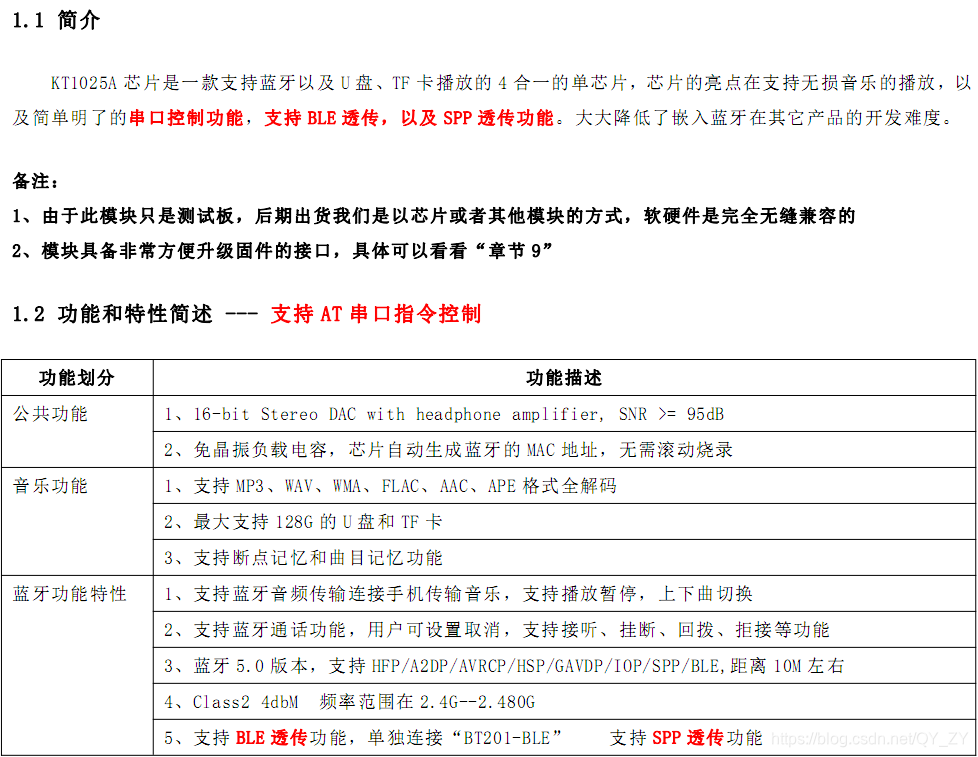
Bluetooth Chip Description:
The KT1025A chip is a single-chip solution supporting Bluetooth audio and data, as well as playback from USB flash drives and TF cards. Its highlights include support for lossless music playback, simple and clear serial port control functions, and support for BLE and SPP pass-through functions. This significantly reduces the development difficulty of embedding Bluetooth in other products. Priced around 3 yuan, it's very popular. The BT201 is a test demo of the KT1025A and KT1025B chips. Function descriptions: 1. 16-bit Stereo DAC with headphone amplifier, SNR >= 95dB; 2. No crystal oscillator or load capacitor required, the chip automatically generates the Bluetooth MAC address, no need for rolling programming; 3. Supports full decoding of MP3, WAV, WMA, FLAC, AAC, and APE formats; 4. Supports up to 128GB USB flash drives and TF cards; 5. Supports breakpoint memory and track memory functions; 6. Supports Bluetooth audio transmission to connect to a mobile phone for music transfer, supports play/pause, and skip tracks; 7. Supports Bluetooth calling function, which can be canceled by the user, supporting answering, hanging up, calling back, and rejecting calls; 8. Bluetooth 5.0 version, supports HFP/A2DP/AVRCP/HSP/GAVDP/IOP/SPP/BLE, with a range of approximately 10 meters; 9. Class 2 4dBM. The frequency range is 2.4G-2.480G5, supports BLE transparent transmission function, and can be connected separately to "BT201-BLE" to support SPP transparent transmission function.
Physical diagram,

schematic diagram and design description:
This project uses STC8H8K64U-45I-LQFP32 as the main controller to communicate with KT1025A via serial port, and can be operated by button control and voice control.
PDF_Bluetooth Voice Speaker.zip
Altium Bluetooth speaker.zip
PADS Bluetooth Voice Speaker.zip
BOM_Bluetooth Voice Speaker.xlsx
93578
AI Voice Box 2
This voice box, based on the ESP32 microcontroller and using the iFlytek Xinghuo large-scale model, is powered by a lithium battery and features a microphone and speaker, enabling continuous dialogue.
This voice box, based on the ESP32 microcontroller and using the iFlytek Xinghuo large-scale model, is powered by a lithium battery and features a microphone and speaker, enabling continuous dialogue.
90299c972fd3b7e779c8a938b0a72c6a.mp4
main.zip
PDF_AI Voice Box 2.zip
Altium AI Voice Box 2.zip
PADS_AI Voice Box 2.zip
BOM_AI Voice Box 2.xlsx
93579
Voltage acquisition device based on STC design
The voltage acquisition device based on STC design is adapted to Paper Airplane serial port software and supports voltage plotting and digital tube display.
STC8H1K08 Simple Voltmeter Function Design
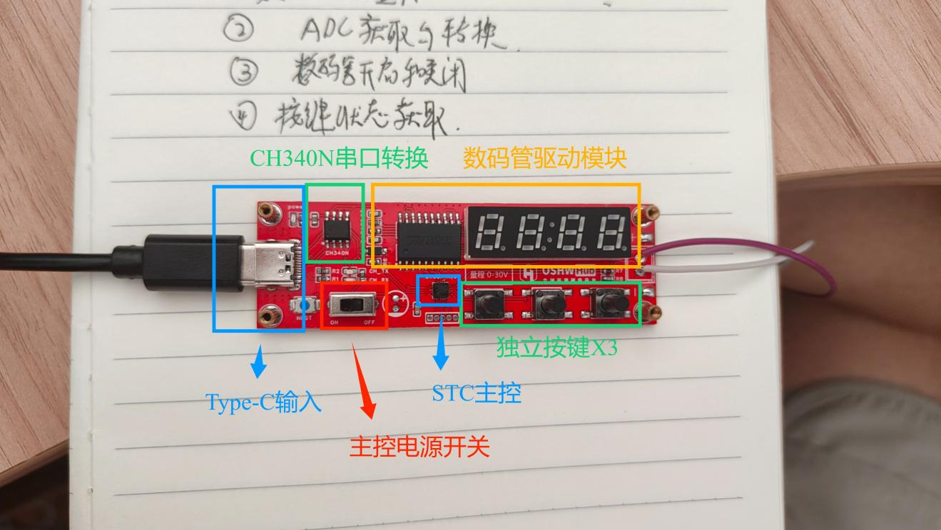
Button Description:
There are three buttons on the PCB, defined from left to right:
Button 1:
Turn the digital tube on/off. Clicking this button turns the digital tube on or off; the digital tube status does not affect voltage acquisition.
Button 2:
Enable serial port output. The device outputs real-time voltage acquisition data to the serial port via Type-C. Voltage changes can be viewed using a serial port plotter on the host computer.
Button 3:
Disable serial port output. The device will not send data to the serial port.
Power Switch :
The two-pin toggle switch on the PCB only controls the power supply to the main control chip STC8H1K08. The power supply for modules such as the digital tube and serial port converter is directly drawn from the Type-C port and is not controlled by this switch.
Usage Instructions:
Switch the main control power switch to the left (ON). Insert the Type-C cable into the computer's USB port. The computer will automatically load the CH340 serial port. After opening the COM port, press button 2 to enable voltage output (1000ms/time). Connect the voltage test wires to the positive and negative terminals of the source under test (marked on the circuit board). Note that the main control power switch must remain ON unless firmware flashing is being performed.
Serial Port Configuration Reference Voltage:
The device's voltage measurement is accomplished through the ADC pin of the 51 microcontroller and a voltage divider circuit. The ADC reference voltage is affected by the power supply voltage. Due to fluctuations in the power supply voltage (5.0±0.5), the measurement voltage error will increase. Therefore, the device can calibrate the reference voltage via the serial port.
Insert the device into the USB port, open the COM port, and use a serial port tool to send the command
"AT+VT,0545". The device will reply: "OK VT=5.45"
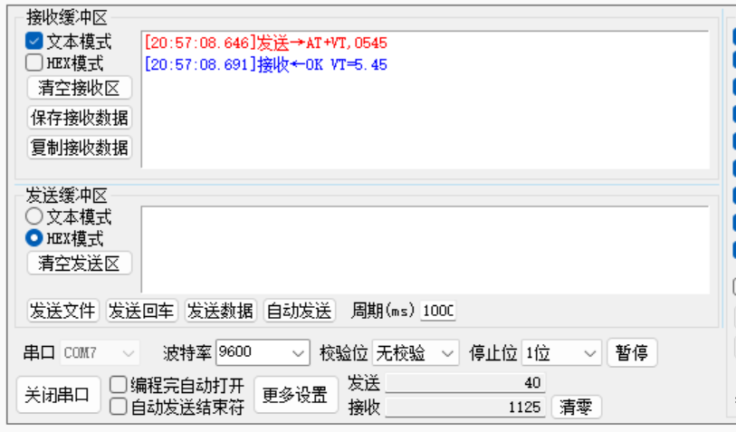
. The device has adjusted the reference voltage and saves the settings after power-down.
Note: The voltage is amplified 100 times from the reference voltage source and set using four digits. If the voltage source is 5.28V, the command is "AT+VT,0528".
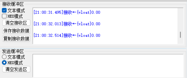
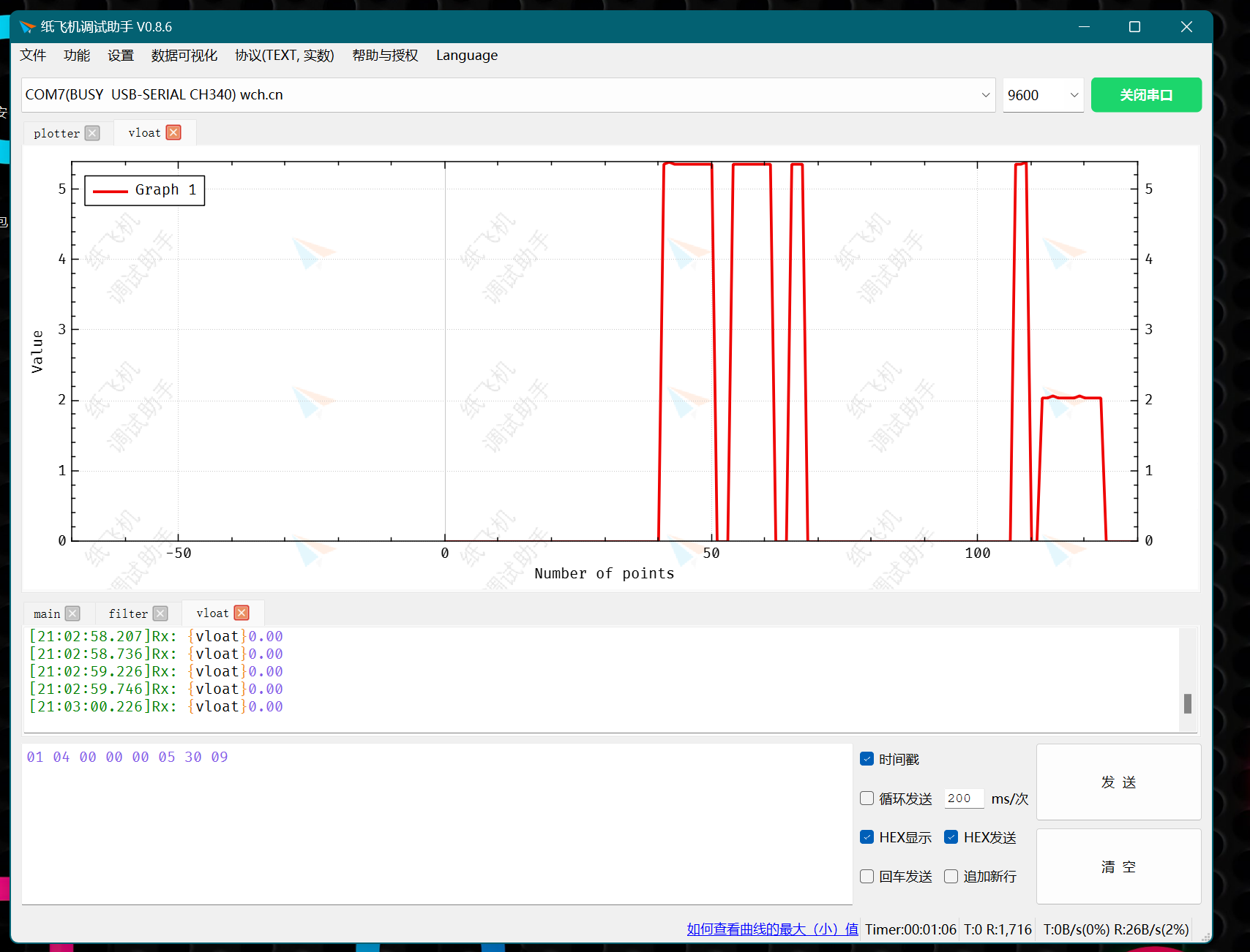
Use a serial port tool to plot voltage changes.
The device is connected to the ComAssistant serial port plotter; the output data has a fixed format that can be recognized and automatically plotted by the software.
Download address: Paper Airplane Debugging Assistant – Official Website (comassistant.cn)
Software tutorial: https://www.bilibili.com/video/BV1E3411E7vu
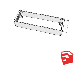
For the shell file:
The attached model source file is developed using SketchUp. Please enlarge by 102% when slicing and printing.
######### Burning frequency 12MHz ############
STC8H1K08 Voltmeter.zip
PDF_Voltage Acquisition Device Based on STC Design.zip
Altium - Voltage Acquisition Device Based on STC Design.zip
PADS_Voltage Acquisition Device Based on STC Design.zip
BOM_Voltage Acquisition Module Based on STC Design.xlsx
93581
electronic


 京公网安备 11010802033920号

 4608H-701-221/681


