I. Introduction
JLCPCB's summer training camp for digital voltmeters and ammeters using the LCPCB CW32 provided abundant project learning materials. I followed the training and designed an entry-level voltmeter and ammeter, which also serves as a new decorative item for my desktop. Although there are some design flaws, they do not hinder the normal use of the voltmeter and ammeter. This design differs from the JLCPCB training camp design in that the plug-in components were replaced with surface-mount components, the layout was optimized to reduce the overall size of the design, and I designed and 3D printed the shell and panel myself. The design was completed on August 17, 2024.
II. Function Introduction
1. Voltage and Current
Simultaneous Sampling and Display. Measure a low-powered battery.

2. Button Calibration Function.
Define 5 working modes. The K1 key is used to switch display modes. The K2 key sets the parameter values for the corresponding mode and saves them to FLASH. The K3 key returns to mode 0.
Mode 0: Displays normal voltage and current values (the upper row of digital tubes displays the voltage value *.V or .*V automatically, the lower row displays the current value _.**A).
Mode 1: 5V voltage calibration setting. The upper row of digital tubes displays 5.05. The lower row displays the current voltage value _.V or ._V. In this mode, the multimeter should be set to 5.00V when measuring the measured bit. Pressing the K2 key will calibrate the current value to 5V.
Mode 2: 15V voltage calibration setting. The upper row of digital tubes displays 5.15. The lower row displays the current voltage value _.V or ._V. In this mode, the multimeter should be set to 15.0V when measuring the measured bit. Pressing the K2 key will calibrate the current value to 15V.
Mode 3: 0.5A current calibration setting. The upper row of digital tubes displays A.0.5. The lower row displays the current current value _.**A. After pressing the K2 key, the current value is calibrated to 0.5A.
Mode 4: Current 1.5A calibration value setting. The upper row of digital tubes displays A.1.5. The lower row displays the current current value *.**A. After pressing the K2 key, the current value is calibrated to 1.5A.
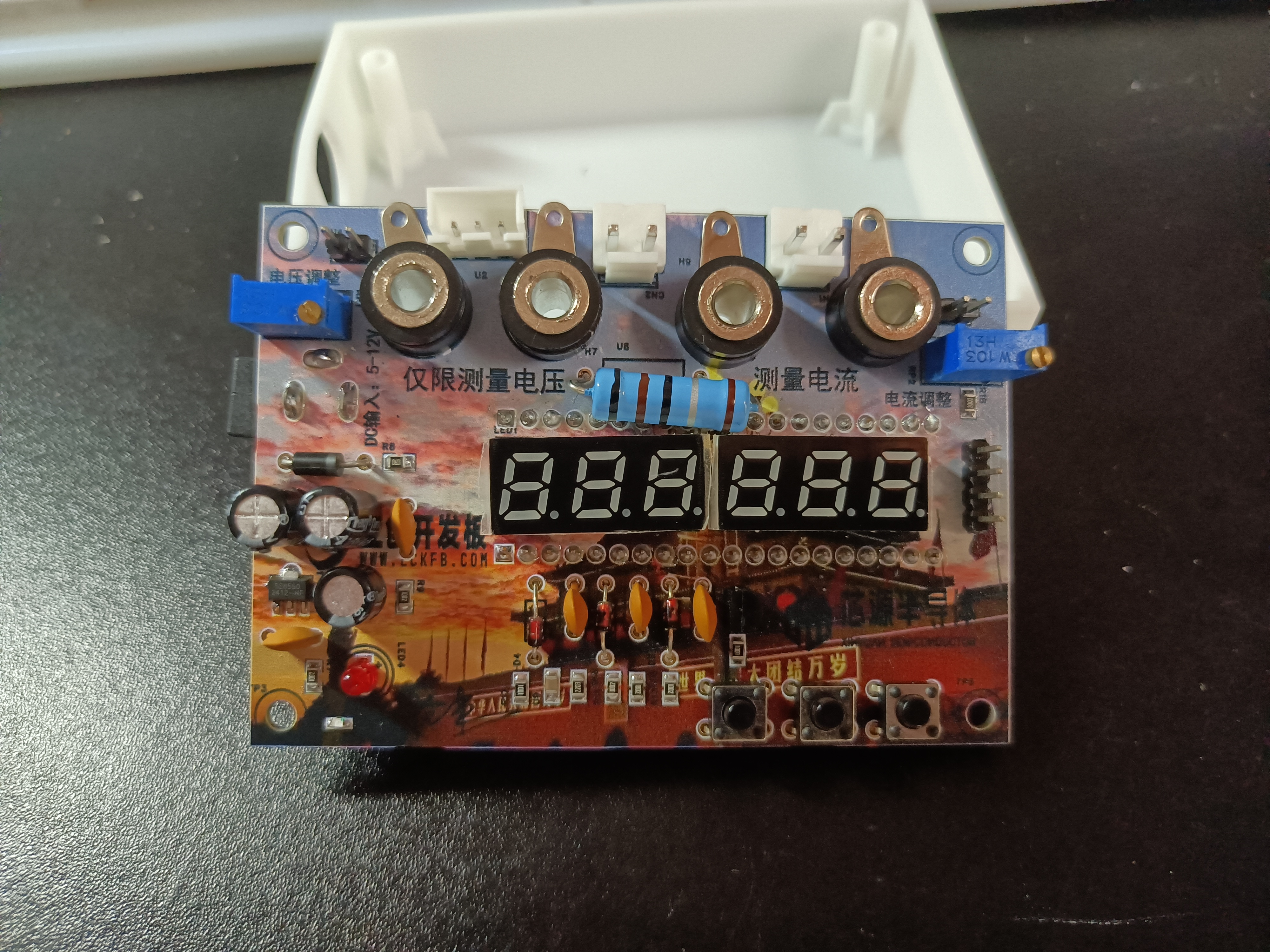
III. Hardware Circuit
Based on the training camp project, the plug-in components are replaced with surface-mount components.
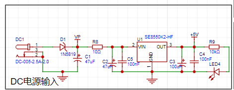
1. LDO (Low Dropout Linear Regulator)
is based on SE8550K2 as the DC power output.
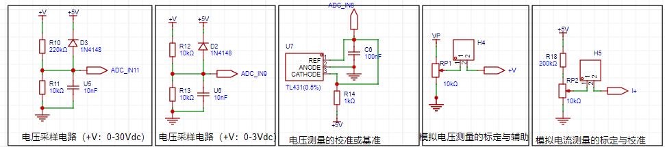
2. Voltage Circuit Sampling Circuit
The project uses a voltage divider circuit to achieve high voltage acquisition. The design can acquire a voltage of 100V, and the current configuration is to acquire a voltage of 0-30V. The project design uses a voltage divider resistor of 220K+10K, so the voltage division ratio is 22:1 (ADC_IN11).
The project uses a low-side current sampling circuit for current detection. The low side of the sampling circuit shares a common ground with the development board's meter interface. The sampling current is 3A, and the selected sampling resistor (R0) is 100mΩ. According to the formula, the voltage and power can be calculated as 3A * 100mΩ = 300mV, 900mW.

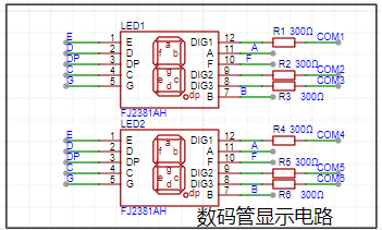
3. The project uses a digital tube as the display unit.
IV. Software Design:
This was my first time working with CW32. I followed a training camp project to design the software, mainly focusing on developing good programming habits.
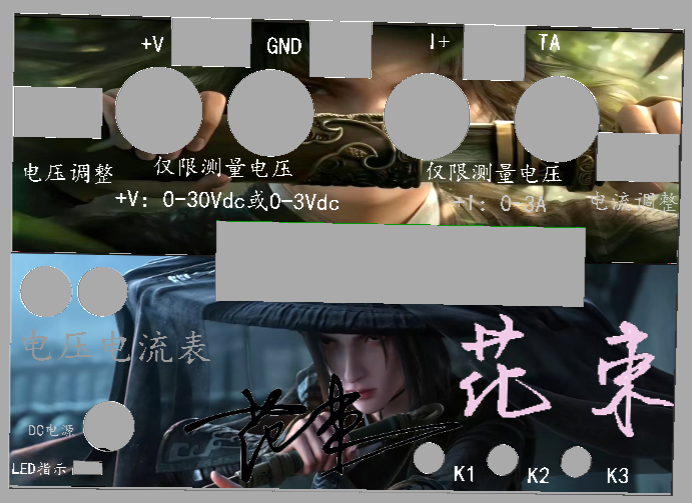
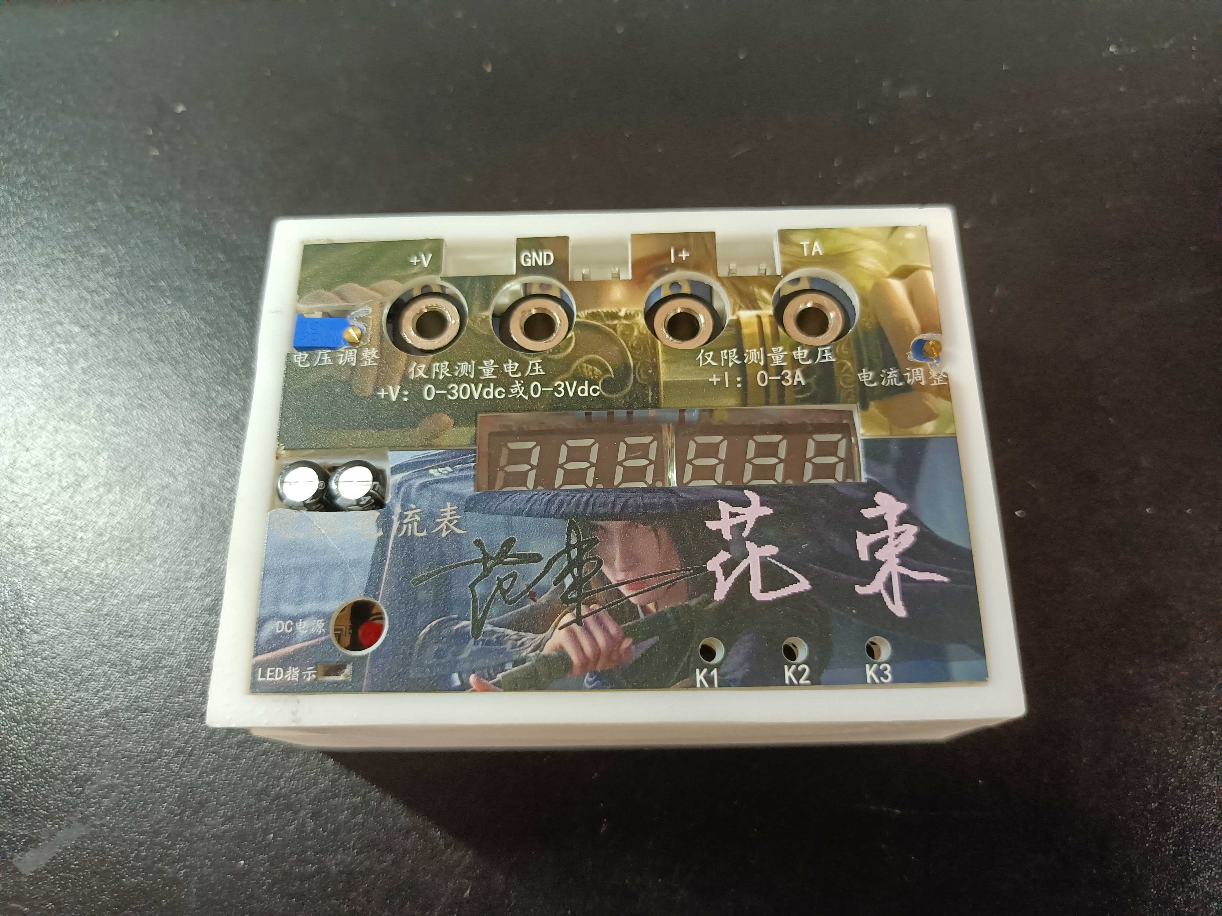
V. Shell and Panel Design:
3D shell design
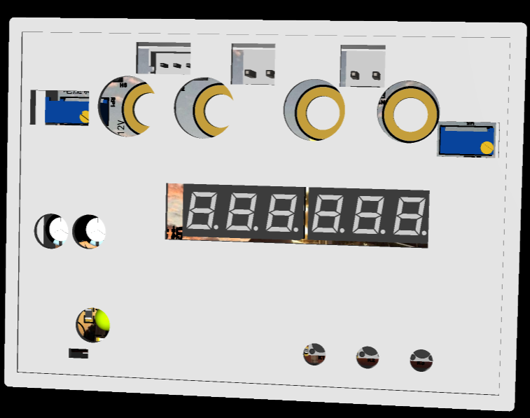
and panel design.
VI. Physical Demonstration


 京公网安备 11010802033920号

 BZV85/C6V2


