this project was designed using KiCad v6 (a very old project), so there is no unconditional free PCB fabrication service available with lCad. The schematic preview is at the bottom, please take note.
If you want to fabricate a PCB, please use Gerber below. The PCB in lCad is imported and is for preview only. The BOM is also below. Please do not use the automatically exported version. For the
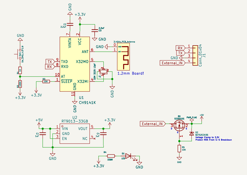
PCB, please use a 1.2mm board thickness.
It's just a BLE Bluetooth serial port, easy to solder and use. It has a built-in reverse connection protection/AT configuration switch.
When using it, just be sure to modify the BLE pass-through parameters.
test images are included.
OSAR is an AR glasses device that is easy to replicate, functional, and cost around 1000 RMB. We welcome contributions from talented individuals to the project.
1.1 Overall Overview
Chapter 1 provides an overview of the project, naturally introducing the assembly method of the optical components.
Chapter 2 details the AR circuitry and programming.
Chapter 3 introduces the current project status.
The entire production process involves assembling the optical components first, aligning them with the screen, and then burning the hardware circuitry into the firmware.
1.2 Features
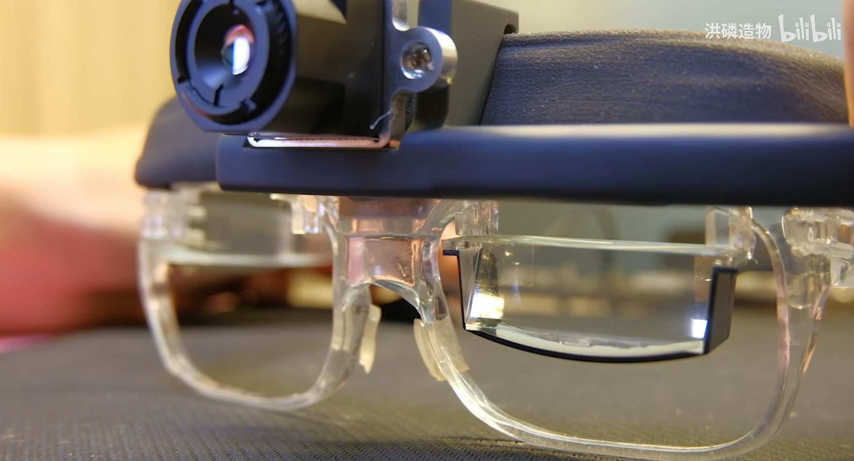
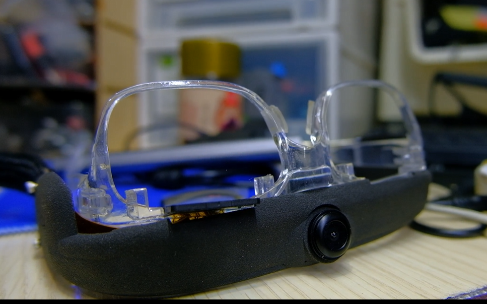
OSAR leans towards exploration and features a 1920x1080 OLED display. The upper part is a detachable
thermal imaging module; after removal, an infrared camera is found inside.
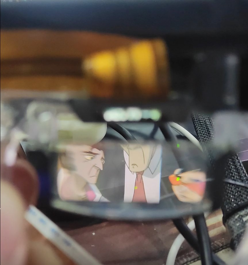
This is the anime viewing function:
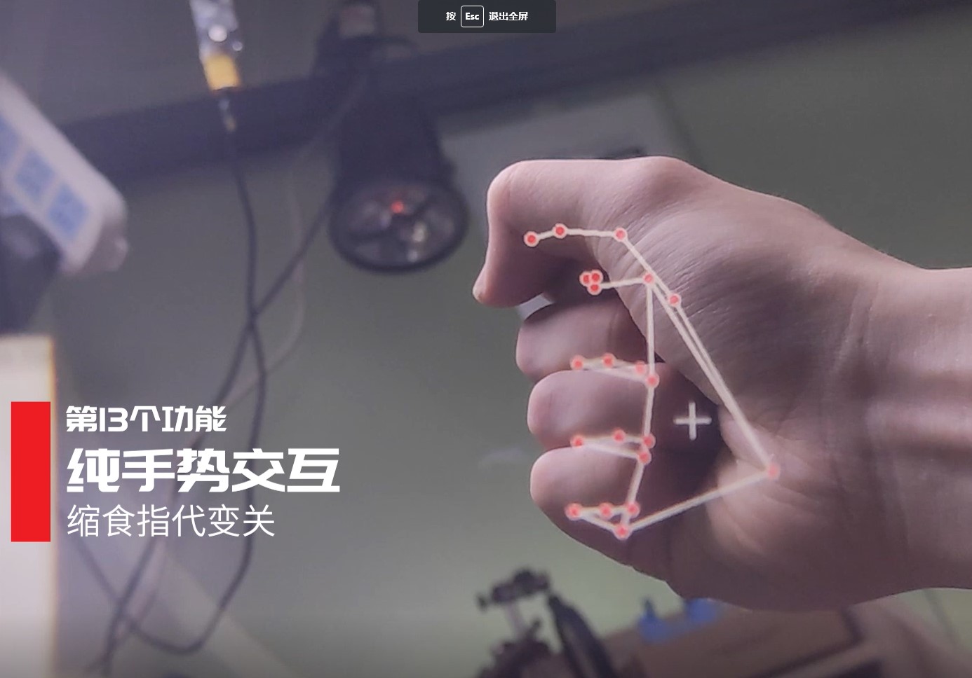
This is the gesture recognition demo (based on midiapipe):
1.3 Motherboard Principles
To drive the display, a computing platform is required. Initially, I tried driving
the display directly from a mobile phone (using the phone's HDMI output), but my self-developed application couldn't access the infrared
camera . Without the infrared camera, the night vision device and my self-made application wouldn't work. I also tried
a development board I designed myself, using JLCPCB's six-layer immersion gold process, running Linux. It drove the optical components without
problems , but it couldn't run Android AR applications, meaning I couldn't see stars or perform measurements. So, is there
a compatible and feature-rich solution? I thought of the embedded Android module commonly used in these advertising machines:
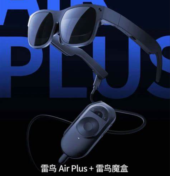
the RK3399, the one shown in the video. Over time, I purchased
the Thunderbird Air AR glasses, which are currently on the market. After market research, I believe that the AR industry in 2024 doesn't
need to be too ambitious, running an Android system with every function to replace a phone. Instead, it should focus on a single, specialized
function, adopting a B2B approach, and becoming a necessity in specific situations. The reason is simple: hardware computing power
and battery life are insufficient, making this approach suitable. Below is the architecture diagram:
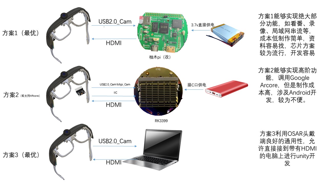
you'll find that AR glasses are essentially just a display with a camera attached to the face, so
connecting to phones, computers, and development boards, including Raspberry Pi, is not a problem. I also used
Raspberry Pi during early testing (how did I end up playing with all the development boards??). Now I've chosen to modify the H6
16-based Yuzuki Pi, as this offers the highest cost-effectiveness, helping you achieve your
core needs—watching anime, thermal imaging/fusion, and night vision—at minimal cost. In other words, it's both practical and cool. For a
thermal imaging tutorial, please see the attached doc file. Available motherboard images:
https://115.com/s/swzzh0c33g7?password=k716&#https://115.com/s/swzzw6a33g7?password=l2c0�
Detailed motherboard information can be found in the PCB section of the project. An HDMI adapter circuit is essential; otherwise, it won't work.

I personally recommend using JLCPCB SMT, as it's difficult to solder the three BGAs on the motherboard successfully on the first attempt.
1.4 Display Section
If you wish to assemble it, please refer to section 1.4.2 for the animated disassembly or the attached video. The blue component at the bottom is
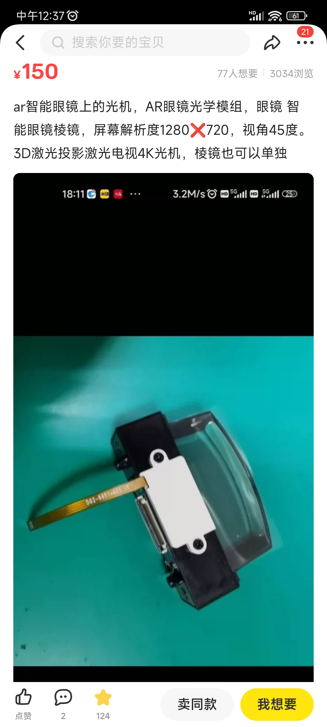
the lens (a combination of a convex lens and a semi-transparent, semi-reflective lens).
1.4.1 Lens Principle
With the screen so close to our eyes, can we really see clearly? The lens in our eyes automatically adjusts its focusing distance,
allowing us to see objects clearly. However, if the distance is too close, it exceeds the eye's focusing ability, meaning we can't see clearly.
VR's solution is to add a lens in front of the screen, making your eyes perceive objects as far away. AR,
based on the same principle, adds a semi-transparent, semi-reflective coating, thus achieving a
superimposed .
1.4.2 Assembly
The key component, the optical lens, can be easily purchased on Xianyu (a second-hand marketplace). After purchasing, you need to
remove the LCOS (Liquid Optical Coating) component. There is no open-source driver available for the LCOS. Replace it with your
own ECX335 screen. Screens can be purchased on Taobao for under 850 RMB.
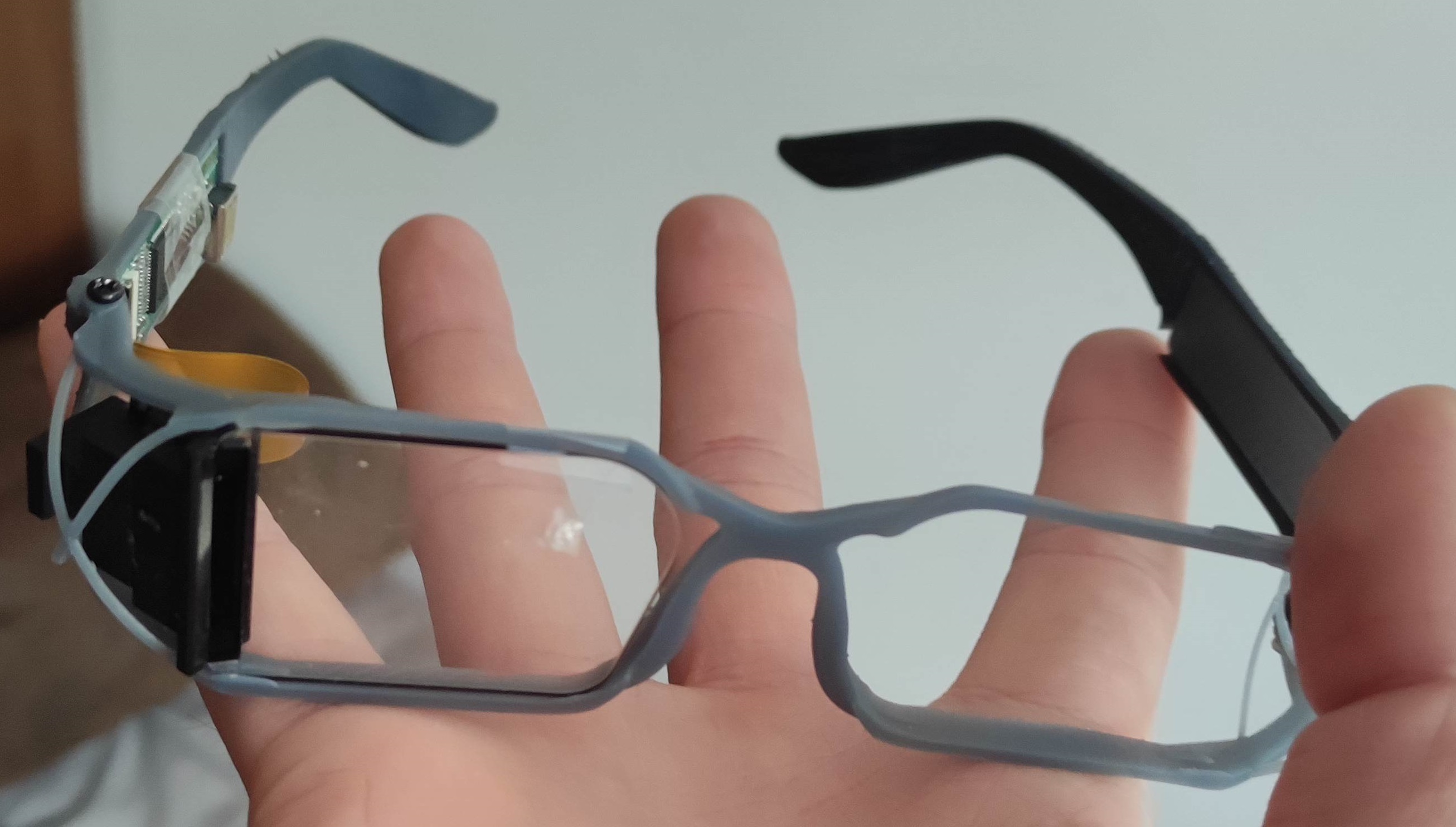
The middle section contains the eyeglass frame, OLED panel, and driver board (model ECX335AF). Above is the camera and its support

. The first step of assembly is installing the camera and lens onto their respective supports (model OV5647 (IR))

. The second step involves installing the ECX335 in the lower section, precisely aligned with the lens's imaging portion.
The driver board is installed in the upper section. The FPC cables for both are not shown in the image, but please handle them carefully during the

final step. The upper and lower sections are then glued together; AB glue is recommended. After gluing, connect the HDMI and USB cables.

The display effect is as shown: no purple fringing or distortion, but the FOV is small, and the brightness is around 300 nits.
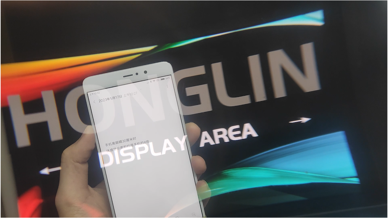


The weight before and after assembly is 67g, which is acceptable.
1.5 Open Source License:
This project is under the MIT license. Commercial development does not require authorization, but the original author's logo and name cannot be used.
1.6 Project Attributes:
This project is being publicly released for the first time and is my original work. This project has not won any awards in other competitions.
1.7 Reference:
Yuzuki Chameleon H616-based Card Computer - JLCPCB EDA Open Source Hardware Platform (oshwhub.com).
The motherboard is modified from Yuzuki Pi, with USB, HDMI, audio, and Ethernet
replaced with onboard interfaces suitable for small spaces. The crystal oscillator part number was modified to match the LCPCB online store.
1.8 Thermal Imaging:
Thermal imaging is essentially a type of camera. Consumer-grade thermal imaging commonly uses USB running the UVC protocol. UVC
is simpler; various software programs can decode it, even without writing your own program. The advantage of my publicly disclosed
method is its low cost, making it more user-friendly for enthusiasts, since it involves buying secondhand goods (laughs). Due to
the large amount of content, I have made it into a separate doc attachment; please download and view it.
2.1 To program OSAR,
you need a TF card reader and an 8GB card.


Image from cv6851453. The hardware connection method is described below:

Because the hardware was given away (as mentioned above), I will explain the specific operation process with pictures and text here.
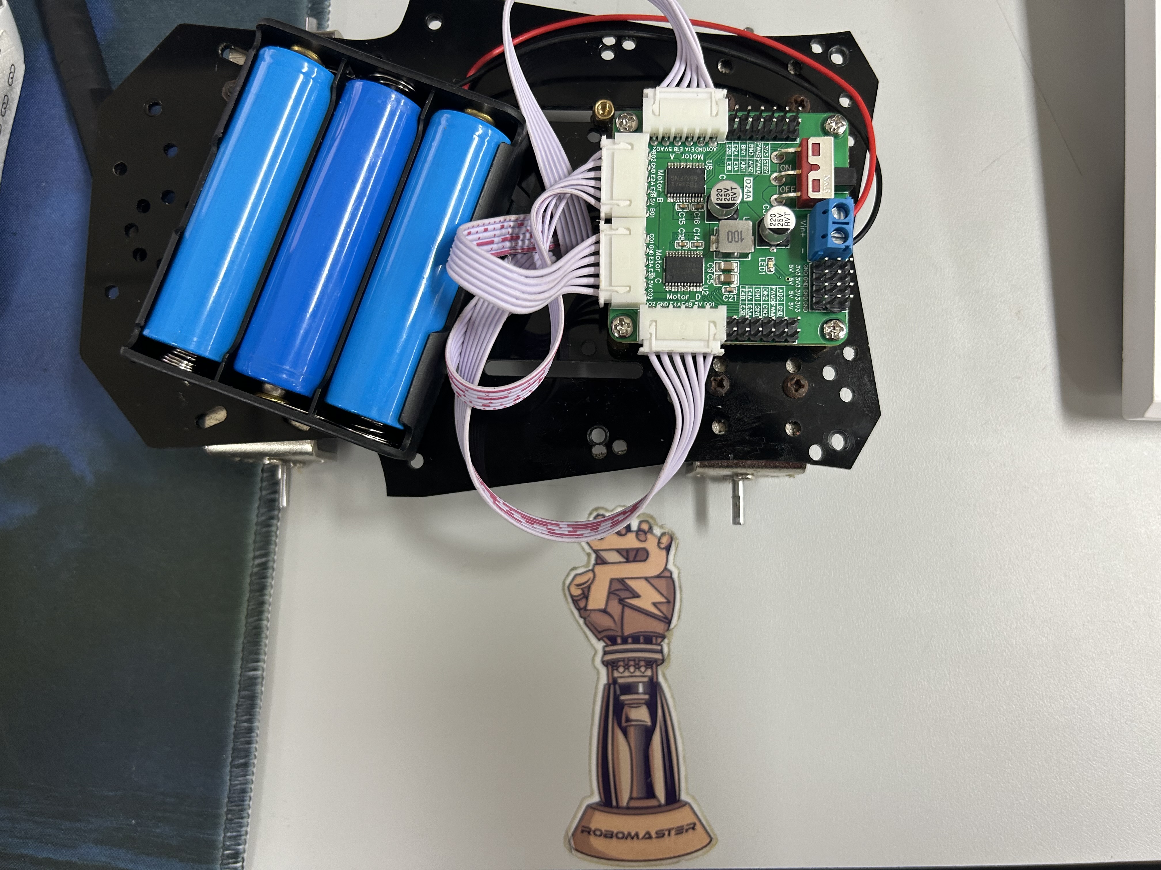
External power supply means you can directly connect a power bank or charger. A USB camera is not mandatory, but
connect it if you have one. Connecting it allows for some interactive development.
The connection method is D- D+ 5V GND from top to bottom. If you need lithium battery power, you can try
connecting the lithium battery directly to the mains (PS and GND). A TF card is required; otherwise, it will draw power from the built-in e-emulator.
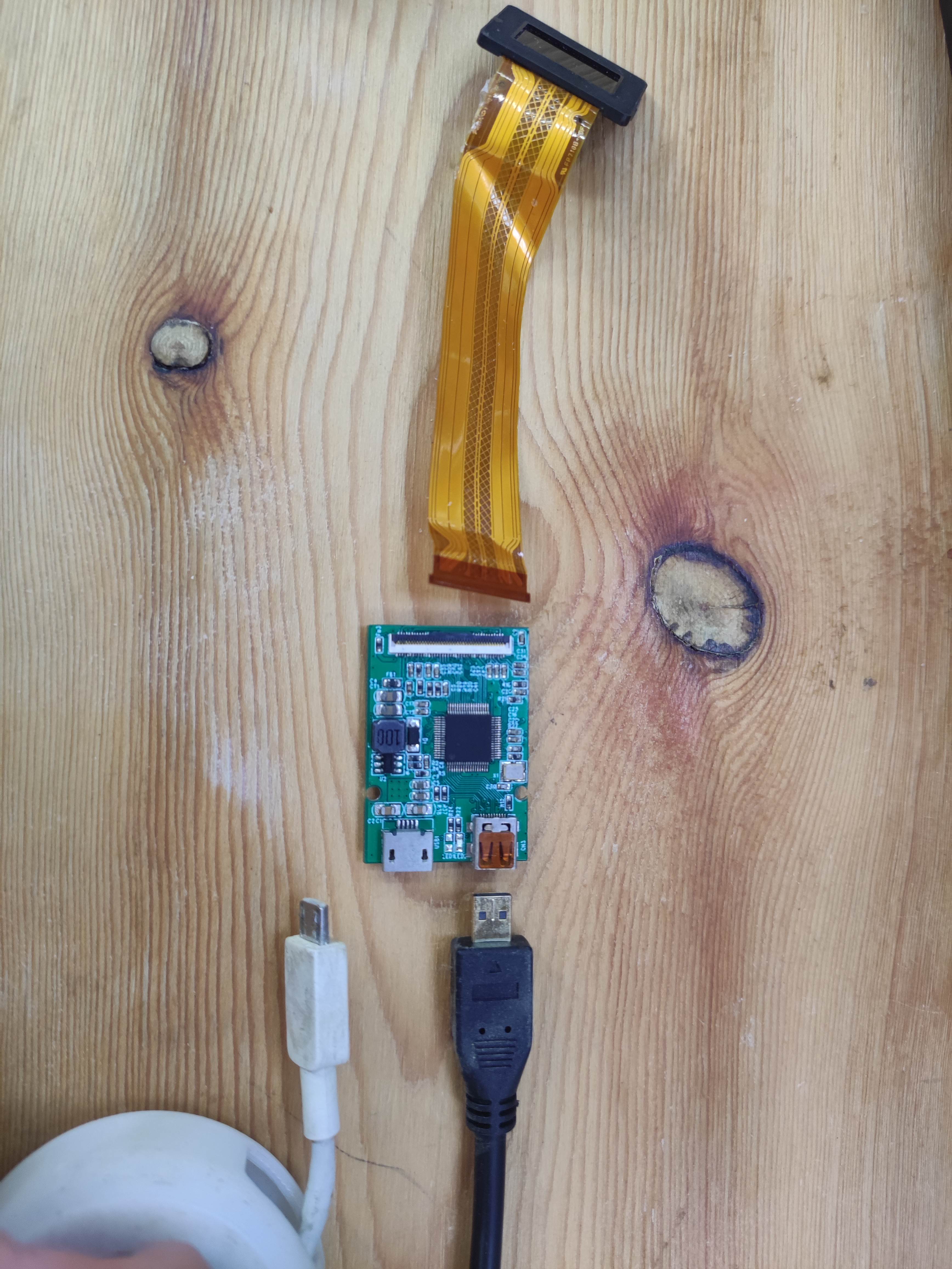
MC boot. The connector in the bottom right corner for the OLED screen refers to the ECX335 driver board. You just need to buy a regular
HDMI to Micro HDMI cable and
connect the driver board (available on Taobao) to the motherboard using an HDMI cable (see picture below). Remember to handle the FPC cable carefully.
After connecting, you will see the system screen. At this point, playing movies and acting as a monitor are no problem

. The assembly of the optical components can skip to section 1.4.2. This section covers the assembly of the circuitry and system flashing.
If you feel that leaving the motherboard exposed is too dangerous,
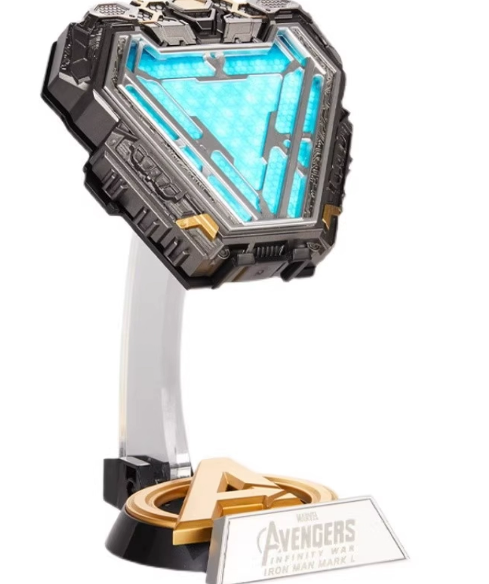
you can do what I did: disassemble an Iron Man suit of clothing, install the battery and motherboard inside,

and then attach it to the suit with a magnet.
This is similar to mainstream AR glasses on the market, allowing users to watch anime and satisfy entertainment needs.
Hopefully, this helps you understand why I said, "AR isn't mysterious; it's like a phone or computer—it accepts
user data input, processes the data through pre-written programs, and finally outputs the results
to the user. The only difference is that AR's display system is more advanced."
3.1 Future Outlook
: I have some good news! The littleAR project has secured investment and plans to produce a mass-produced device by the middle of next year.
I'm also developing a new generation of waveguide-based AR systems, as shown in the image above. Talented individuals are welcome to join us.
USB camera adapter bracket.
A beginner's tutorial that anyone can understand. (mp4)
The ESP32-C3-FOC development board uses the ESP32C3 chip as the main controller and supports rapid development of brushless motors using simpleFOC. The power input is 12V.
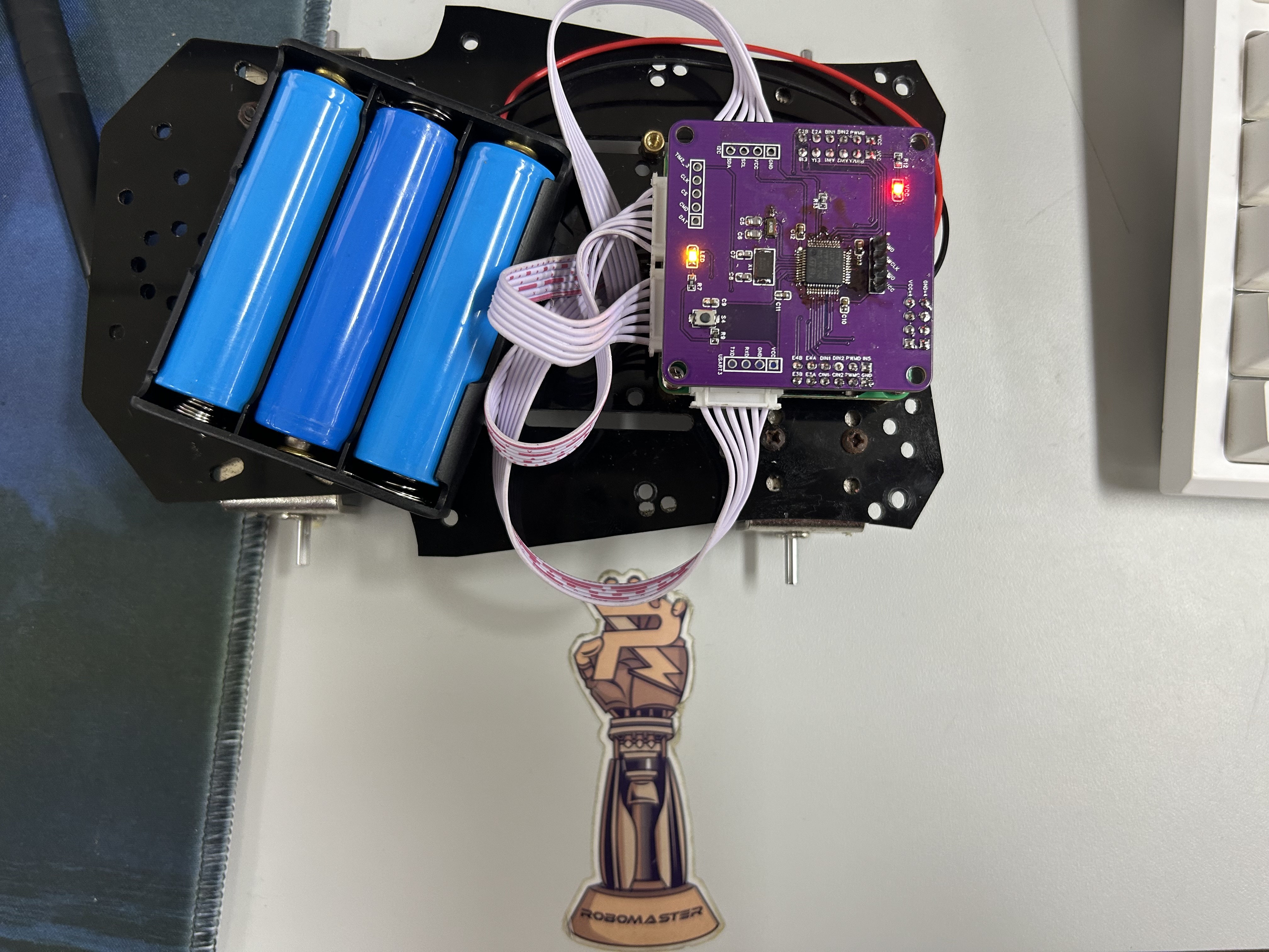
 This was the first board I built, and there were some errors; this version has corrected them.
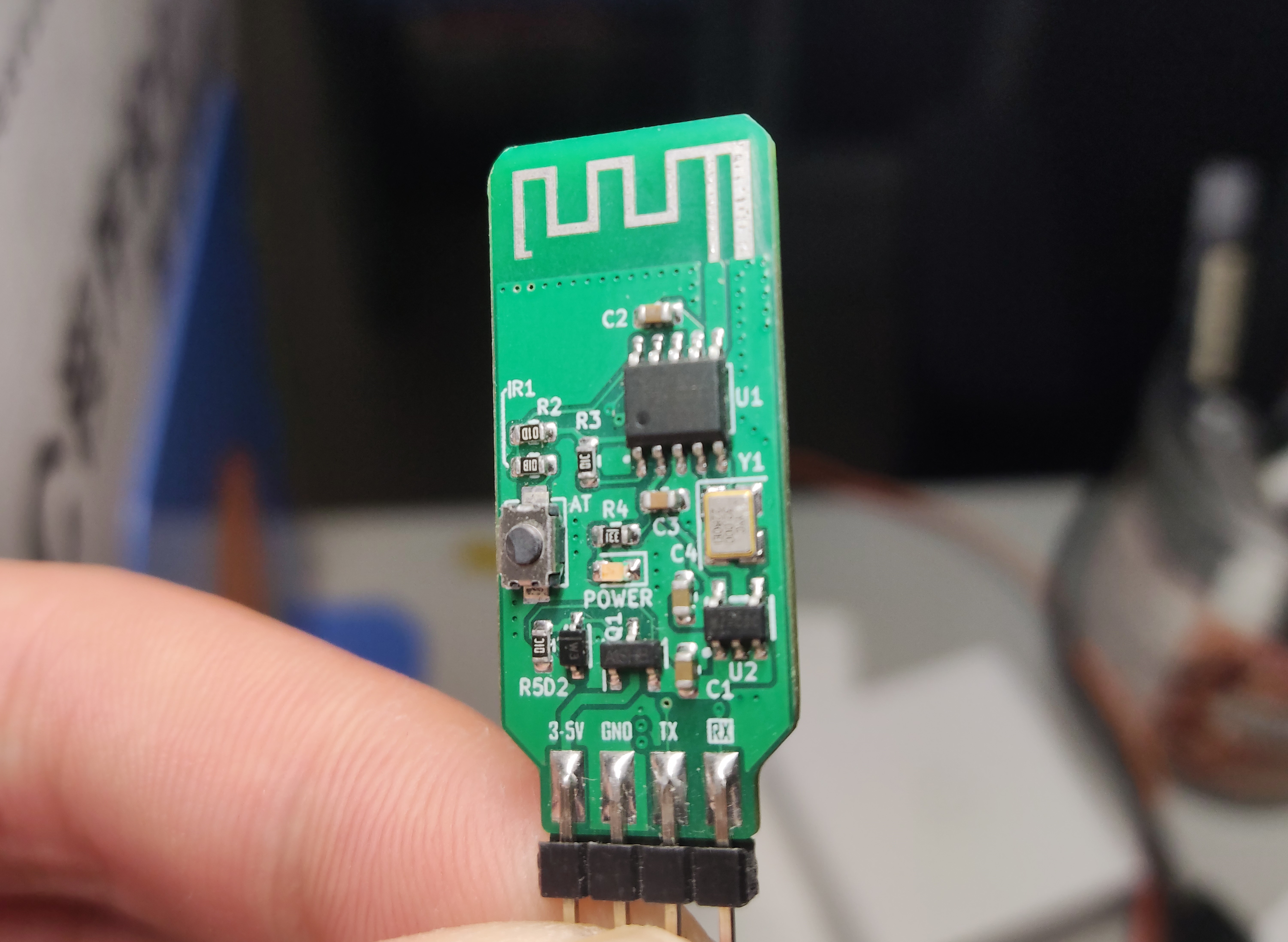 When using it, just be sure to modify the BLE pass-through parameters.
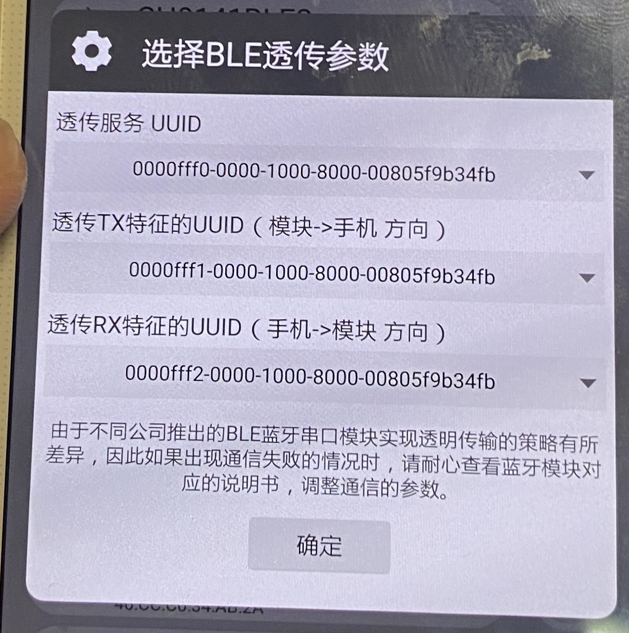
 test images are included.
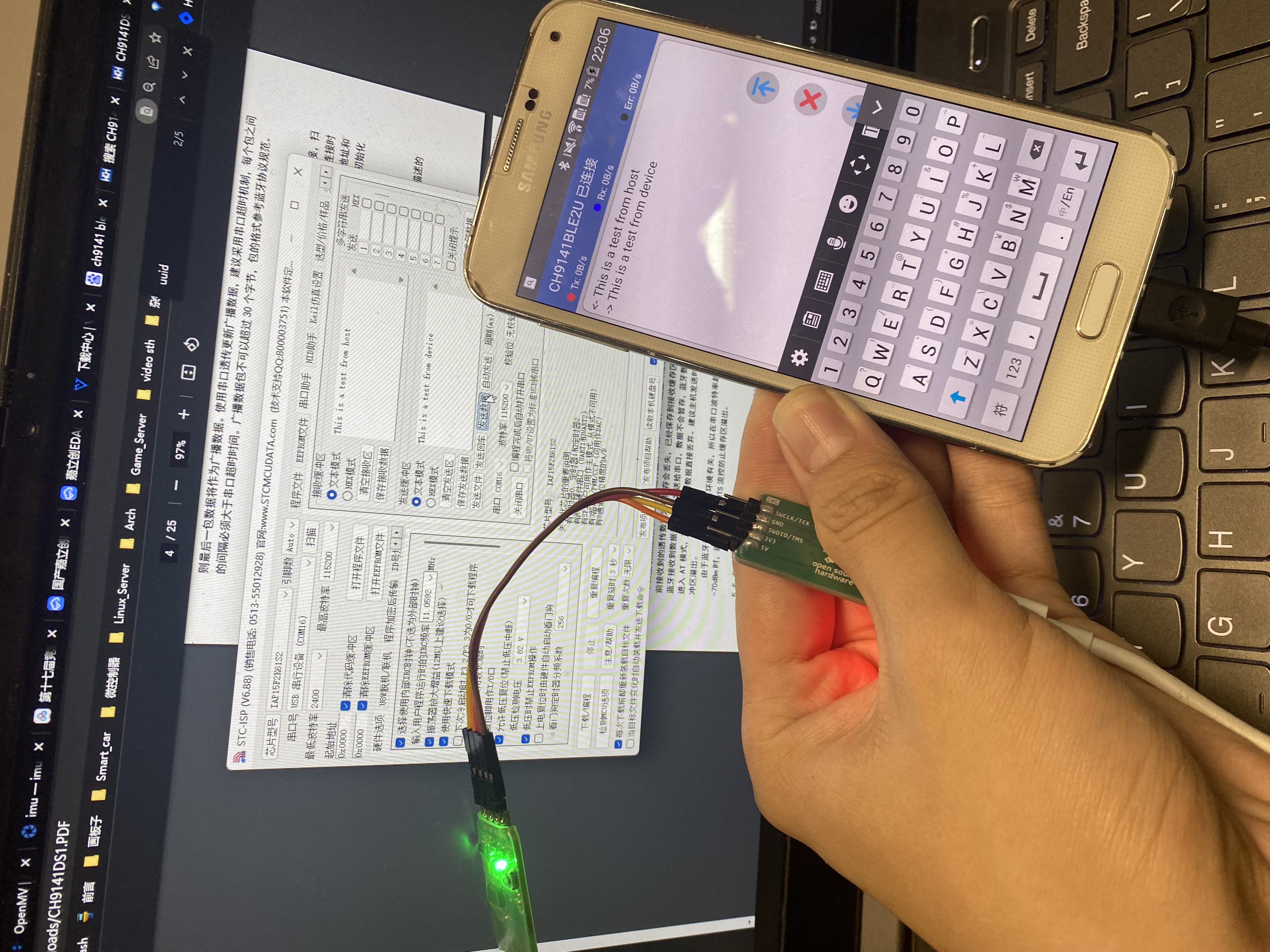


 京公网安备 11010802033920号

 PIC17LC766-16/PT


