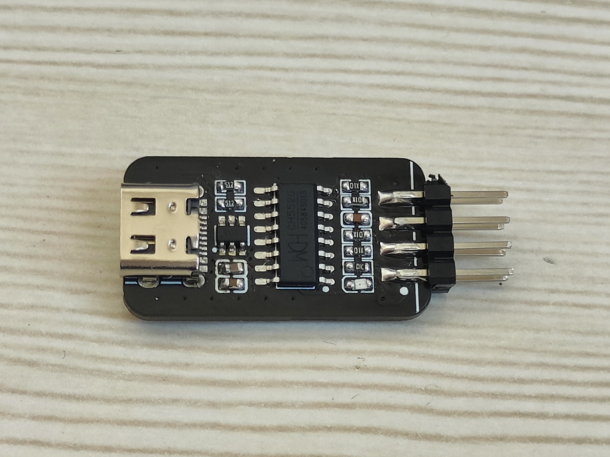
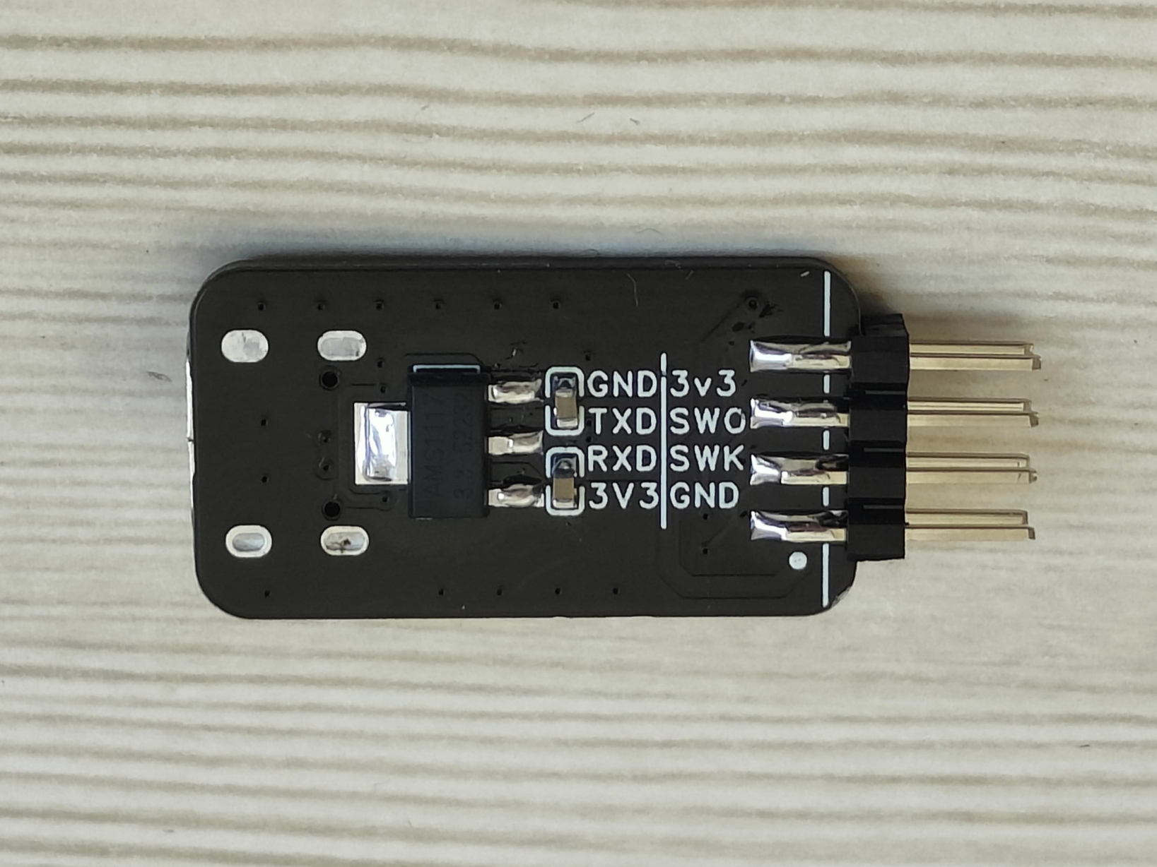
This is a modified version of Liangshanpai's DAPLINK, with only the LDO part added and the layout modified. The interface has been changed to the common XH2.54 header.
the actual product image at https://gitee.com/lcsc/lspiclink.git for details.
The driver is available at the link; the touch functionality has been tested.
Based on the Taishanpai 4-inch 86-inch screen adapter - LCSC open-source hardware platform (oshwhub.com), modified
platform Wildfire Lubancat 2BTB version
MIPI DSI0
chip platform: RK3568

2024/08/19 Touch has been updated.
Different development boards have different DTSI, please pay attention to identification.
Example: I chose rk3568-lubancat-2io-dsi-800p.
Put the following content into the device tree:
&i2c1 {
status = "okay";
clock-frequency = ;
FT5X06@38 {
status = "okay";
compatible = "edt,edt-ft5406";
reg = ;
interrupt-parent = ;
interrupts
= ; reset_gpio = ;
wake_gpio=;
touchscreen-size-x = ;
touchscreen-size-y = ;
touch_type = ;
}; The device tree node directly calls the edt-ft5x06.c file without needing a patch
. Since it's unknown which makefiles Luban Cat uses , some defs are loaded for this driver, and other drivers are disabled. It's recommended to disable unnecessary models to improve compilation speed and prevent address errors and driver loading failures. # CONFIG_TOUCHSCREEN_GOODIX=y # CONFIG_TOUCHSCREEN_GSLX6801=y # CONFIG_TOUCHSCREEN_GSLX680_PAD=y # CONFIG_TOUCHSCREEN_GSLX680_VR=y # CONFIG_TOUCHSCREEN_GSL3673=y # CONFIG_TOUCHSCREEN_GSL3673_800X1280=y # CONFIG_TOUCHSCREEN_GSL3676=y # CONFIG_TOUCHSCREEN_HYN_CST2XX=y # CONFIG_TOUCHSCREEN_WACOM_W9013=y# CONFIG_TOUCHSCREEN_GT1X=y#CONFIG_TOUCHSCREEN_FTS=y#CONFIG_TOUCHSCREEN_ROCKPI_FT5406=yCONFIG_TOUCHSCREEN_EDT_FT5X06=y //86 screen driver# CONFIG_TOUCHSCREEN_CYPRESS_CYTTSP5=y# CONFIG_TOUCHSCREEN_CYPRESS_CYTTSP5_DEVICETREE_SUPPORT=y# CONFIG_TOUCHSCREEN_CYPRESS_CYTTSP5_I2C=y# CONFIG_TOUCHSCREEN_CYPRESS_CYTTSP5_DEVICE_ACCESS=y# Adding a # before CONFIG_TOUCHSCREEN_CYPRESS_CYTTSP5_LOADER=y indicates that I mainly modified lubancat2_android11_defconfig //This configuration file is most likely the one I compiled for MIPI800P . I also tested lubancat2_buildroot_defconfig, lubancat2_defconfig , rockchip_defconfig , and rockchip_linux_defconfig. I haven't done specific testing yet . The file path is in kernel/arch/arm64/configs. The driver file path is in kernel/drivers/input/touchscreen/makefile. bj-$(CONFIG_TOUCHSCREEN_EDT_FT5X06) += edt-ft5x06.o This driver is loaded by default. If it's not there, add it yourself and then compile. Complete device tree // SPDX-License-Identifier: (GPL-2.0+ OR MIT) /* * Copyright (c) 2020 Rockchip Electronics Co., Ltd. * */ &route_dsi0 { status = "okay"; connect = ; }; &video_phy0 { status = "okay"; }; &dsi0_in_vp0 { status = "okay"; }; &dsi0_in_vp1 { status = "disabled"; }; &dsi0 { status = "okay"; rockchip,lane-rate = ; power-supply = ; dsi0_panel:panel@0 { compatible = "simple-panel-dsi"; reg = ; backlight = ; reset-gpios = ; enable-delay-ms = ; prepare-delay-ms = ; reset-delay-ms = ; init-delay-ms = ; unprepare-delay-ms = ;
disable-delay-ms = ;
size,width = ;
size,height = ;
dsi,flags = ;
dsi,format = ;
dsi,lanes = ;
panel-init-sequence = [
23 01 02 7A C1
23 01 02 20 E0
23 01 02 21 E0
23 01 02 22 11
23 01 02 23 02
23 01 02 24 02
23 01 02 25 12
23 01 02 26 00
23 01 02 27 02
23 01 02 28 02
23 01 02 29 12
23 01 02 34 80
23 01 02 36 02
23 01 02 86 29
23 01 02 B5 A0
23 01 02 5C FF
//23 01 02 14 43 // Test mode
//23 01 02 2A 49 // Test mode
23 01 02 2A 01
23 01 02 56 92
23 01 02 6B 72
23 01 02 69 12
23 01 02 10 10
23 01 02 11 88
23 01 02 B6 20
23 01 02 51 20
23 01 02 09 10
05 78 01 11
05 14 01 29
];
panel-exit-sequence = [
05 00 01 28
05 00 01 10
];
disp_timing: display-timings {
native-mode = ;
dsi0_timing: timing {
clock-frequency = ;
hactive = ;
hfront-porch = ;
hback-porch = ;
hsync-len = ;
vactive = ;
vfront-porch = ;
vback-porch = ;
vsync-len = ;
hsync-active = ;
vsync-active = ;
de-active = ;
pixelclk-active = ;
swap-rb = ;
swap-rg = ;
swap-gb = ;
};
};
ports {
#address-cells = ;
#size-cells = ;
port@0 {
reg = ;
panel_in_dsi0: endpoint {
remote-endpoint = ;
};
};
};
};
ports {
#address-cells = ;
#size-cells = ;
port@1 {
reg = ;
dsi0_out_panel: endpoint {
remote-endpoint = ;
};
};
};
};
&i2c1 {
status = "okay";
clock-frequency = ;
FT5X06@38 {
status = "okay";
compatible = "edt,edt-ft5406";
reg = ;
interrupt-parent = ;
interrupts = ;
reset_gpio= ;
wake_gpio=;
touchscreen-size-x = ;
touchscreen-size-y = ;
touch_type = ;
};
};
&route_dsi1 {
status = "okay";
connect = ;
};
&video_phy1 {
status = "okay";
};
&dsi1_in_vp0 {
status = "disabled";
};
&dsi1_in_vp1 {
status = "okay";
};
&dsi1 {
status = "okay";
power-supply = ;
dsi1_panel:panel@0 {
status = "okay";
compatible = "simple-panel-dsi";
reg = ;
backlight = ;
reset-gpios = ;
enable-delay-ms = ;
prepare-delay-ms = ;
reset-delay-ms = ;
init-delay-ms = ;
unprepare-delay-ms = ;
disable-delay-ms = ;
size,width = ;
size,height = ;
dsi,flags = ;
dsi,format = ;
dsi,lanes = ;
panel-init-sequence = [
39 05 04 FF 98 81 03
15 05 02 01 00
15 05 02 02 00
15 05 02 03 53
15 05 02 04 D3
15 05 02 05 00
15 05 02 06 0D
15 05 02 07 08
15 05 02 08 00
15 05 02 09 00
15 05 02 0a 00
15 05 02 0b 00
15 05 02 0c 00
15 05 02 0d 00
15 05 02 0e 00
15 05 02 0f 28
15 05 02 10 28
15 05 02 11 00
15 05 02 12 00
15 05 02 13 00
15 05 02 14 00
15 05 02 15 00
15 05 02 16 00
15 05 02 17 00
15 05 02 18 00
15 05 02 19 00
15 05 02 1a 00
15 05 02 1b 00
15 05 02 1d 00
15 05 02 1e 40
15 05 02 1f 80
15 05 02 20 06
15 05 02 21 01
15 05 02 22 00
15 05 02 23 00
15 05 02 24 00
15 05 02 25 00
15 05 02 26 00
15 05 02 27 00
15 05 02 28 33
15 05 02 29 33
15 05 02 2a 00
15 05 02 2b 00
15 05 02 2c 00
15 05 02 2d 00
15 05 02 2e 00
15 05 02 2f 00
15 05 02 30 00
15 05 02 31 00
15 05 02 32 00
15 05 02 33 00
15 05 02 34 03
15 05 02 35 00
15 05 02 36 00
15 05 02 37 00
15 05 02 38 96
15 05 02 39 00
15 05 02 3a 00
15 05 02 3b 00
15 05 02 3c 00
15 05 02 3d 00
15 05 02 3e 00
15 05 02 3f 00
15 05 02 40 00
15 05 02 41 00
15 05 02 42 00
15 05 02 43 00
15 05 02 44 00
15 05 02 50 00
15 05 02 51 23
15 05 02 52 45
15 05 02 53 67
15 05 02 54 89
15 05 02 55 AB
15 05 02 56 01
15 05 02 57 23
15 05 02 58 45
15 05 02 59 67
15 05 02 5a 89
15 05 02 5b AB
15 05 02 5c CD
15 05 02 5d EF
15 05 02 5e 00
15 05 02 5f 08
15 05 02 60 08
15 05 02 61 06
15 05 02 62 06
15 05 02 63 01
15 05 02 64 01
15 05 02 65
00 15 05 02 66 00
15 05 02 67
02 15 05 02 68 15
15 05 02 69 15
15 05 02 6a 14
15 05 02 6b 14
15 05 02 6c 0D
15 05 02 6d 0D
15 05 02 6e 0C
15 05 02 6f 0C
15 05 02 70 0F
15 05 02 71 0F
15 05 02 72 0E
15 05 02 73 0E
15 05 02 74 02
15 05 02 75 08
15 05 02 76 08
15 05 02 77 06
15 05 02 78 06
15 05 02 79 01
15 05 02 7a 01
15 05 02 7b 00
15 05 02 7c 00
15 05 02 7d 02
15 05 02 7e 15
15 05 02 7f 15
15 05 02 80 14
15 05 02 81 14
15 05 02 82 0D
15 05 02 83 0D
15 05 02 84 0C
15 05 02 85 0C
15 05 02 86 0F
15 05 02 87 0F
15 05 02 88 0E
15 05 02 89 0E
15 05 02 8A 02
39 05 04 FF 98 81 04
15 05 02 6E 2B
15 05 02 6F 37
15 05 02 3A 24
15 05 02 8D 1A
15 05 02 87 BA
15 05 02 B2 D1
15 05 02 88 0B
15 05 02 38 01
15 05 02 39 00
15 05 02 B5 02
15 05 02 31
25 15 05 02 3B 98
39 05 04 FF 98 81 01
15 05 02 22 0A
15 05 02 31 00
15 05 02
53 3D
15 05
02 55 3D
15
05 02 50
A0 00
15 05 02 A1 21
15 05 02 A2 35
15 05 02 A3 19
15 05 02 A4 1E
15 05 02 A5 33
15 05 02 A6
27 15 05 02 A7 26
15 05 02 A8 AF
15 05 02 A9 1B
15 05 02 AA 27
15 05 02 AB 8D
15 05 02 AC 1A
15 05 02 AD 1B
15 05 02 AE 50
15 05 02 AF 26
15 05 02 B0 2B
15 05 02 B1 54
15 05 02 B2 5E
15 05 02 B3 23
15 05 02 C0 00
15 05 02 C1 21
15 05 02 C2 35
15 05 02 C3 19
15 05 02 C4 1E
15 05 02 C5 33
15 05 02 C6 27
15 05 02 C7 26
15 05 02 C8 AF
15 05 02 C9 1B
15 05 02 CA 27
15 05 02 CB 8D
15 05 02 CC 1A
15 05 02 CD 1B
15 05 02 CE 50
15 05 02 CF 26
15 05 02 D0 2B
15 05 02 D1 54
15 05 02 D2 5E
15 05 02 D3 23
39 05 04 FF 98 81 00
15 78 02 11 00
15 05 02 29 00
];
panel-exit-sequence = [
05 78 01 28
05 00 01 10
];
disp_timings: display-timings {
native-mode = ;
dsi1_timing: timing {
clock-frequency = ;
hactive = ;
vactive = ;
hsync-len = ;
hback-porch = ;
hfront-porch = ;
vsync-len = ;
vback-porch = ;
vfront-porch = ;
hsync-active = ;
vsync-active = ;
de-active = ;
pixelclk-active = ;
};
};
ports {
#address-cells = ;
#size-cells = ;
port@0 {
reg = ;
panel_in_dsi1: endpoint {
remote-endpoint = ;
};
};
};
};
ports {
#address-cells = ;
#size-cells = ;
port@1 {
reg = ;
dsi1_out_panel: endpoint {
remote-endpoint = ;
};
};
};
};
&i2c5 {
status = "okay";
clock-frequency = ;
gt911_2: gt911_2@5d {
status = "okay";
compatible = "goodix,gt911";
reg = ;
interrupt-parent = ;
interrupts = ;
reset-gpios = ;
irq-gpios = ;
};
};
&route_hdmi {
status = "disabled";
};
&hdmi_in_vp0 {
status = "disabled";
};
&hdmi_in_vp1 {
status = "disabled";
};
&hdmi {
status = "disabled";
};
视频效果见附件
PDF_Wildfire Luban Cat CAT2 MIPI to RGB666 86-inch screen converter with driver.zip
Altium_Wildfire Luban Cat CAT2 MIPI to RGB666 86-inch screen converter with driver.zip
PADS_Wildfire Luban Cat CAT2 MIPI to RGB666 86-inch screen converter with driver.zip
BOM_Wildfire Luban Cat CAT2 MIPI to RGB666 86-inch screen converter with driver.xlsx
EBAZ4205 expansion board, with I/O pins, buttons, UART, WS2812, and HDMI.
0. Background and Information Sharing:
The EBAZ4205 is a classic mining board with a long history. Its low price makes it a popular choice for many users trying out the ZYNQ platform. It has a relatively high availability on Xianyu (a Chinese online marketplace), and its price has remained stable below 40 RMB for years.
Undeniably, compared to a standard development board, the EBAZ4205 is more difficult to learn and requires some hardware modifications. (
Sharing some useful resources: "
Learning ZYNQ from Scratch (Based on the Mining Card EBAZ4205) (Part 1)" https://blog.csdn.net/Turix/article/details/109738107
(Power saving: Hardware modifications needed include
shorting an unsoldered anti-backflow diode to allow power to the interface;
adding a PL clock source, or using a PS to provide the clock;
soldering the SD card slot yourself;
Boot mode switching requires consulting the schematic and either removing or reconnecting resistors, or using jumper wires to bring out MIO4/5 and adding switches;
correcting the XDAC power connection, which is not connected due to a design flaw and needs to be shorted.)
xjtuecho / EBAZ4205 https://github.com/xjtuecho/EBAZ4205 )
(The repository shares a KiCAD-redrawn EBAZ4205 project, even including schematics, which is more convenient than viewing PDFs.)
Elrori / EBAZ4205 https://github.com/Elrori/EBAZ4205
(The repository shares some useful tutorials, including attempts with Linux and HDMI.)
Others:
Xiaomeige Xilinx ZYNQ https://www.bilibili.com/list/watchlater?oid=319104657&bvid=BV1zw41117HS (A good tutorial for getting started with Vivado software.)
Verilog Hardware Description Language https://www.bilibili.com/video/BV12y4y1v7V3/ (May require some understanding of Verilog and digital electronics.)
XinYi ZYNQ Tutorial https://ax7010-20231-v101.readthedocs.io/zh-cn/latest/index.html (The experimental routines and the routine code in the repository can be referenced. Although I didn't buy their boards (lol)
1. Precautions

The onboard CH343 is used for PL simulation serial port printing. If not used, the short cap can be removed to save two IOs. If

RGB is not used, the 0-ohm resistor R15 can be removed to save one IO.
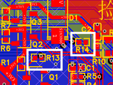
For HDMI display, HPD and CEC signals are not required. They are only useful when the relevant functions are needed. If these functions are not used, the 0-ohm resistors R13 and R14 can be removed to save two IOs.
Other:
1. The pin length of the HDMI female connector may exceed the thickness of the board, causing part of the pin to be exposed. When using the heating table, if the board is laid flat, the HDMI female connector may be pushed up, resulting in a cold solder joint.
2. Insert the three female connectors into the EBAZ4205 first, do not solder immediately. First adjust the height of the two boards so that they fit perfectly, and then solder them to fix them. This is the same reason why screws should not be tightened at the beginning.
3. When prototyping, you can select "Place 5*5 QR code in the specified position".
4. The HDMI project environment provided in the attachment is Vivado 2024.1.


An ADC (Analog-to-Digital Converter) is an indispensable key component in electronic systems. It converts continuous analog signals into digital signals, enabling digital processing and analysis. ADCs play a crucial role in signal conversion, measurement and data acquisition, control system input, and communication and signal processing. Their widespread application has promoted the intelligent and precise control of electronic equipment across various industries, making them a key factor driving modern technological progress.
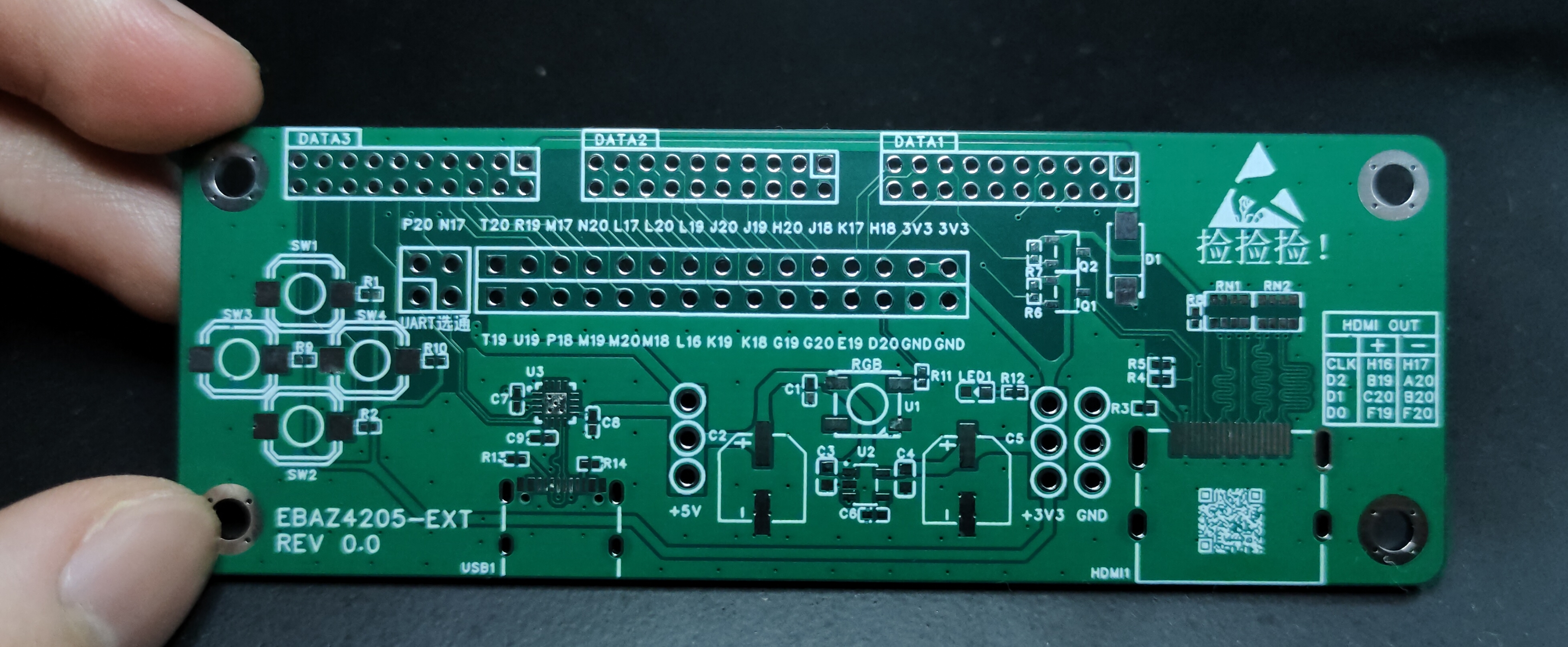
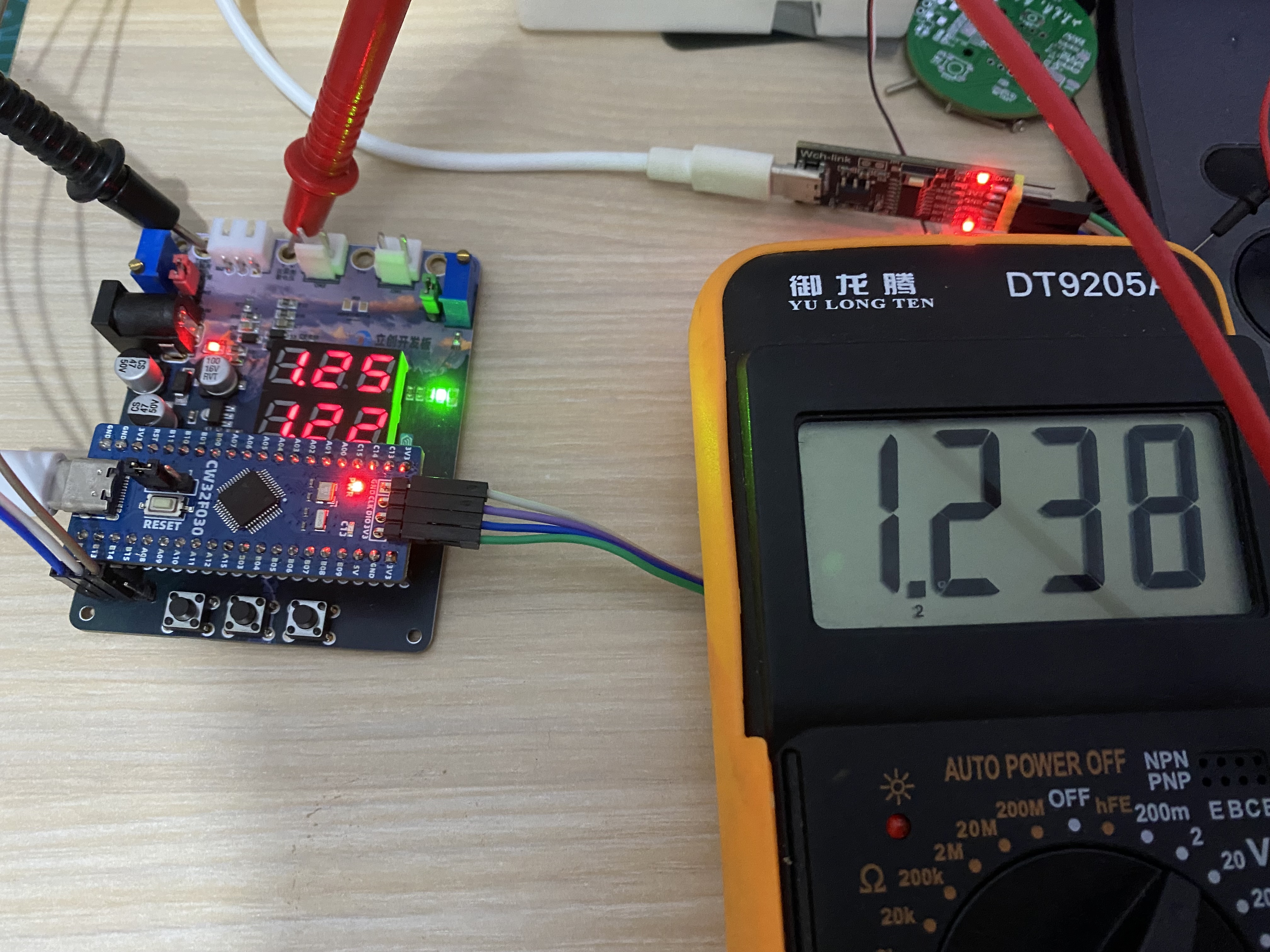
This project is a replica of a training camp voltmeter and ammeter. The core board uses the domestically produced Wuhan Xinyuan Semiconductor CW32 as the main controller, with a reduced PCB size and an additional casing. The display effect is shown in the figure:
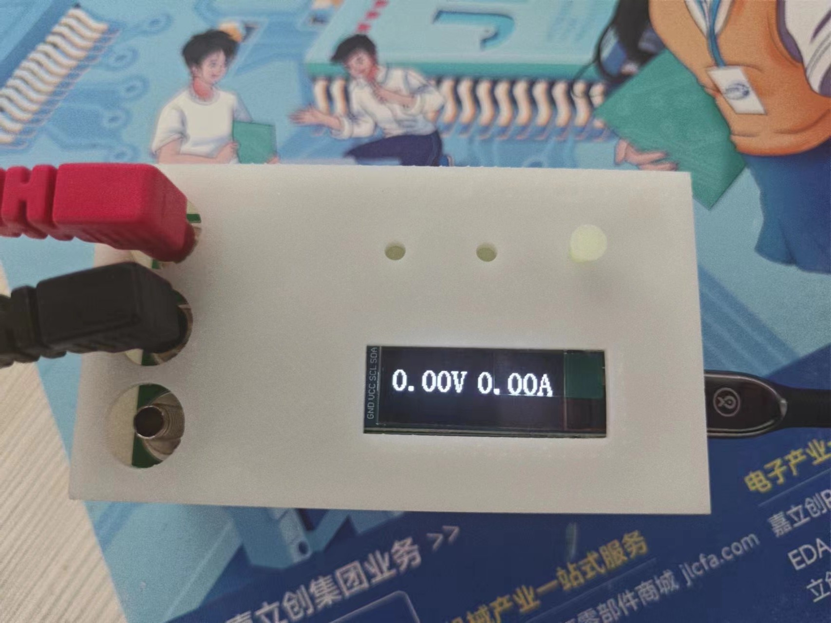
Measuring a 3V button battery:

CW32.stl
CW32 button.stl
hardware.zip
PDF_DIY Voltmeter and Ammeter.zip
Altium_DIY Voltage and Current Meter.zip
PADS_DIY Voltage and Current Meter.zip
BOM_Homemade Voltage and Current Meter.xlsx
93098
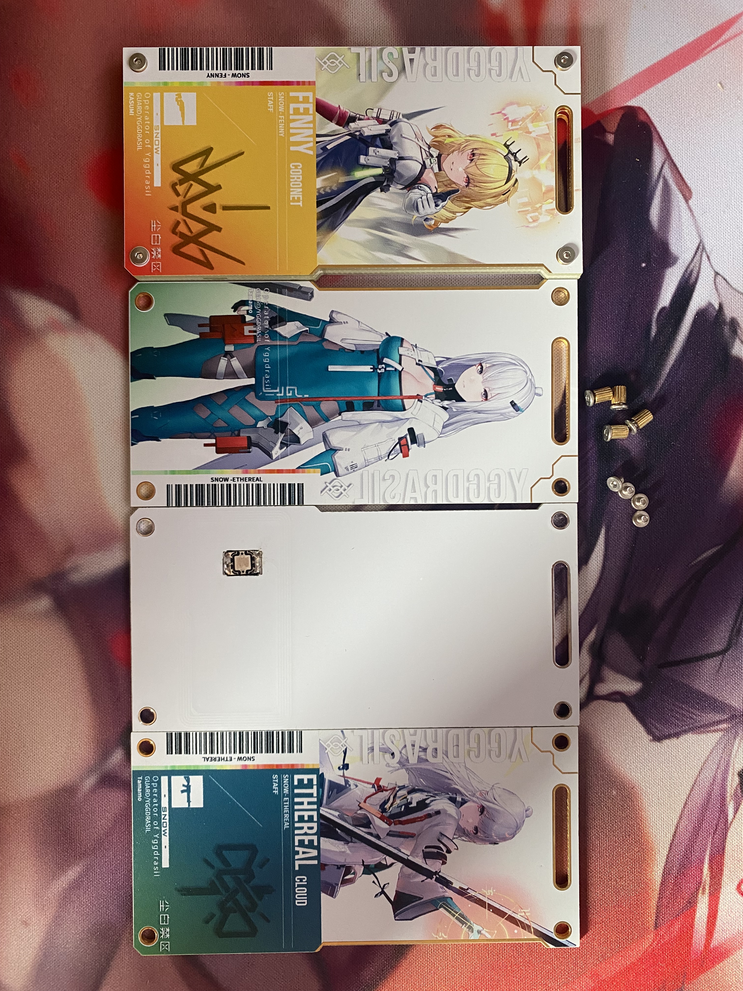
Dust White Forbidden Zone: Arknights Pass NFC Card/Public Transport Card
The Dust White Forbidden Zone features an NFC card/bus card designed to resemble the Arknights pass.
Design Introduction
This design is a modified version of several projects. To hide and protect the chip, it has been modified into a stacked NFC card/bus card composed of three PCBs (two color silkscreen PCBs with a regular PCB with coils and pads sandwiched in between). This modification wasn't simply because stacking three PCBs is more comfortable to handle.
Color Silkscreen Image Design
The color silkscreen image style is modified from the Arknights pass image style. All images used in the modified version are from the "Dust White Forbidden Zone" forum.
PCB Introduction
This project contains two PCBs:
1. Middle Circuit Layer PCB
This PCB has coils and pads, mainly used for soldering the NFC chip/bus card chip and for communication. The NFC chip uses a 5x10mm or smaller COB package. If you want to solder a bus card chip like us, please ensure your bus card chip supports NFC functionality before removing it to ensure convenient recharging later.
2. Top and Bottom Color Silkscreen Layer PCBs
This PCB does not contain any circuit design and is only for decoration. You can modify the color silkscreen images on the PCB according to your preferences.
Prototyping
: 1. Number of PCB boards for the middle layer circuit
: 5 pieces. Solder mask color: White is recommended.
Other options can be left as default (remember to claim the coupon for free).
2. Number of boards for the top and bottom color silkscreen layers
: 10 pieces. Solder mask color: White. Pad plating: Immersion gold. Character process: JLCPCB EDA color silkscreen printing
. Other options can be left as default. The price for prototyping 5 color silkscreen PCBs is the same as for 10 pieces; only the shipping fee will be charged separately. 10 color silkscreen PCBs and 5 regular PCBs can be stacked into 5 sets.
Materials needed:
1. M2x4 double knurled studs *4 (outer diameter preferably less than or equal to 3.2mm)
2. M2x2 flat head hex screws *8 (head diameter 4mm, suitable screwdriver Φ1.27mm or Φ1.3mm)
3. NFC chip/bus card chip; NFC chip should be a 5x10mm or smaller COB package chip. If you're like me and want to solder a bus card chip, please make sure your bus card chip supports NFC functionality before removing it to ensure convenient top-up later.
Other materials
assembly video: https://www.bilibili.com/video/BV1FWvrewE4N/
Dust White Forbidden Zone Pass Template Link: https://pan.baidu.com/s/1F0HrMr1ZeUbAKjqgXWEClg?pwd=snow
Extraction code: snow
Note: It's best to download the template from a cloud drive, as it may have been modified.
Modification Log
August 16, 2024
1. Partially modified the image template and re-uploaded it
. 2. Added Cassia, Fanny-Radiance, and Reeve-Infinite Vision. Image
References
1. Circuit and PCB Design Reference
https://oshwhub.com/242534lbw/ai-li-xi-ya-NFCka
https://oshwhub.com/zhiyuan338/fan-ka
2. Pad Reference
https://oshwhub.com/kctp/fanka
3. Original Color Silkscreen Image Source
https://www.cbjq.com/ 4. Color silkscreen image design reference :
https://www.bilibili.com/video/BV16P411Z729/
fonts.zip
Completed images.zip
Dust White Forbidden Zone (Ark Pass-like) .psd
PDF_Dust White Forbidden Zone Imitation Arknights Pass NFC Card - Public Transportation Card.zip
Altium_Dust White Forbidden Zone Imitation Arknights Pass NFC Card_Public Transportation Card.zip
PADS_Dust White Forbidden Zone Imitation Arknights Pass NFC Card_Public Transportation Card.zip
BOM_Dust White Forbidden Zone Imitation Arknights Pass NFC Card_Bus Card.xlsx
93099
CW32-based digital voltage and current meter
Digital voltage and current meter based on LCSC GeoStar CW32
I. Project Introduction
I have always been a lighting fanatic, proficient in lighting LEDs and digital tubes, but I have never been familiar with measurement programs. In this training camp, I made a simple digital voltage and current meter using the LCSC Skystar CW32 development board to try to learn the methods of measurement and reading between circuits. Thanks to LCSC for letting me experience the powerful one-stop service again. Through this project, I gained a deeper understanding of functions such as color screen printing, 3D printing, and panel making.


II. Hardware Part
1. Power Supply Step-Down Circuit

The power supply is provided by the SE8550K2, a low dropout linear regulator that can support a maximum input of 40V. Since the project does not require a large current, an LDO step-down is used.
[1] The schematic diagram not only shows the pin connections of each component, but also indicates the current flow direction in the circuit design. First, low-frequency filtering is done through electrolytic capacitors, and then high-frequency noise is filtered out through small-capacity capacitors.
[2] When designing the DC plug, attention should be paid to the inner diameter of the DC socket. Common ones are DC2.1 and DC2.5. Make sure that the power connector and DC socket are suitable.
[3] The reverse connection protection design uses Schottky diodes (metal + semiconductor), with a low forward voltage of 0.2V-0.3V, suitable for fast switching and low voltage drop. Common models are SS14 and 1N5819. The easily confused switching diode is a typical PN junction, with a voltage drop of 0.6V-1.0V, suitable for digital and pulse circuits. Common model is 1N4148.
[4] Overcurrent protection and short circuit protection can be effectively achieved by connecting a 10R resistor in series in the circuit. The common power of 0603 package resistors is mainly 100mW. P=UI=I²R. After overcurrent, the resistor burns out to prevent damage to subsequent circuits.
2. Voltage sampling circuit

[1] The common battery voltage sampling circuit is similar to the low-side voltage circuit on the right. It collects the external voltage by dividing the voltage equally between two 10K resistors. U=AD/4096×Vref×2
【2】The high-side voltage sampling circuit uses a 220K+10K resistor to divide the voltage, U=(R/Rtotal)xUsource-->U_ADC=10K/(220K+10K)×Vmeasured. Since the reference voltage is 1.5V, the maximum measurable voltage is 34.5V. U=AD/4096×Vref×(220K+10K)/10K
【3】Through diode forward clamping, when the measured voltage is too large, the pin voltage is forced to clamp to 5V+ voltage drop to prevent chip pin damage. Detailed explanation of diode clamping circuit and limiting circuit
3. Current sampling circuit
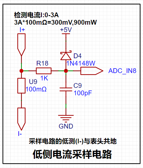
【1】The current is collected through a 100mR sampling resistor. The project design range is 0-3A, P=I²R-->9×100mR=900mW, so the power should be selected from the common 1W package resistor.
[2] The circuit uses direct pin connection and does not use a current sensing amplifier, so the voltage amplification factor is 1. I=U/R, and the measured current is calculated from the value collected by the ADC pin: I=AD value/collection range×reference voltage/sampling resistor-->I=AD/4096×Vref×10
[3] A 1K resistor is connected in series to limit the current and prevent damage to the ADC pin, and it forms an RC low-pass filter with the back-end capacitor to reduce high-frequency noise.
[4] The sampling resistor should be connected in Kelvin during layout.
4. The TL431 reference voltage
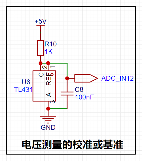
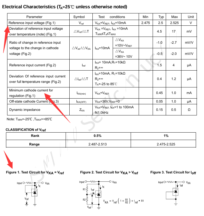
is provided by using the TL431 circuit to provide a 2.5V reference voltage (approximately 2.48V in actual measurement). According to the chip datasheet, when pins 1 and 2 of the chip are connected, VKA=VREF.
The recommended maximum current for IKA is 1mA, and the current limiting resistor R=(5V-2.5V)/0.001A=2.5K. However, the chip sink current can reach 100mA with little damage.
*For example, P=UI=2.5V100mA=0.25W, so the current limiting resistor should be a power resistor with a power greater than 0.25W. **
5. Display and operation circuit

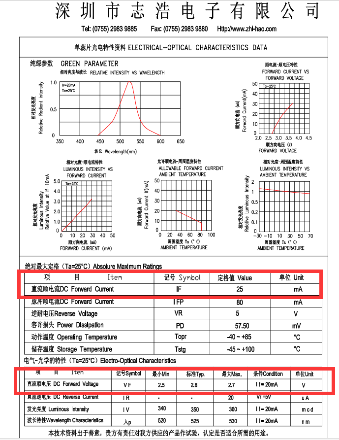
[1] Since the chip I/O often has a sinking current capability greater than a pulling current capability, the LED is designed to be active low level (bright). In order to reduce the current consumption of the LED, some LED brightness is abandoned, the types of device parameters are reduced, and the current limiting resistor of the LED is selected as 10K. The maximum forward current of the red LED is 20mA, and the minimum resistance is R=(5V-1.5V)/I=175Ω; I=U/R->3.5V/10K=0.35mA LED current limiting resistor analysis
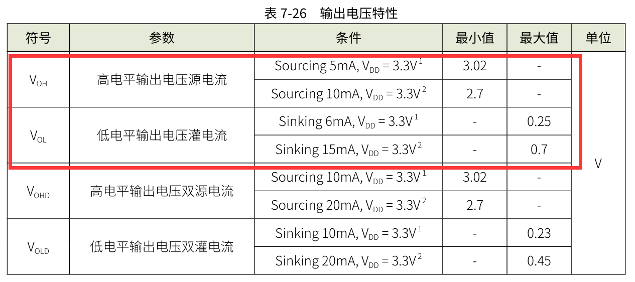
[2] Two 0.28-inch three-digit common cathode digital tubes are used for data display. According to the datasheet, the maximum driving current of the digital tube is 35mA, the driving voltage is 2.7V-2.9V, the microcontroller IO port can output 3.3V level, the maximum sink current input is 25mA, R=U/I-->3.3V/0.025A=132Ω. Therefore, a 300R resistor->3.3V/300R=11mA can be used to light up the digital tube.

!! After searching around, it seems that only this chip with a relatively small current was found. (rough search) !!

III. Physical Production
[1] Most of the circuit uses 0603 package. First, solder the surface mount part, and then solder the through part.
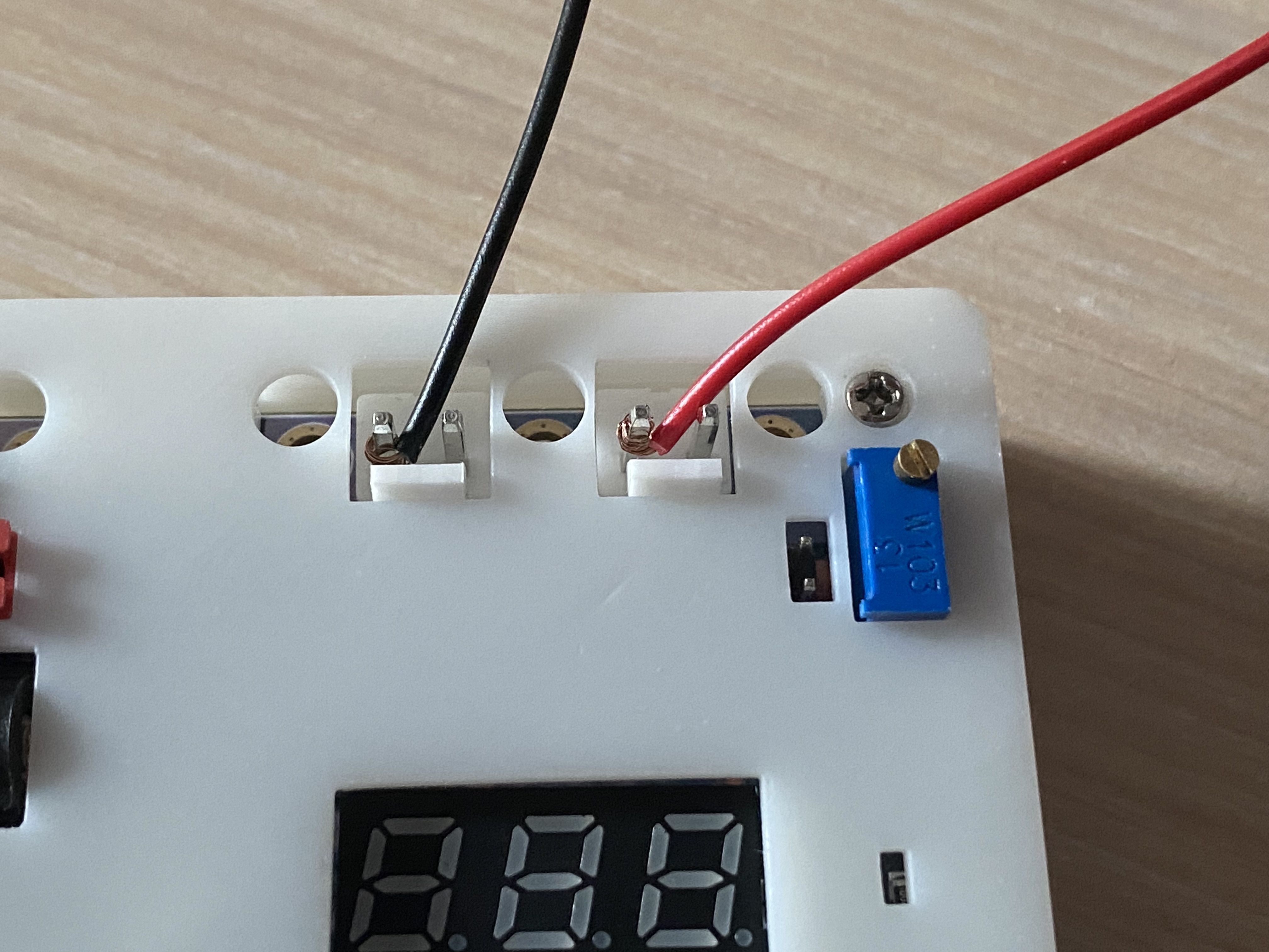
[2] If you want to use the 3.96mm×2P wire-to-board pin header for convenience, you can replace it with a 2.54mm×2P header to connect the commonly used DuPont wires, but the overcurrent capacity will affect the measurement range. (This time, DuPont wire was directly wrapped around the terminal block for easy measurement)
IV. Software Part
1. Compiler Part
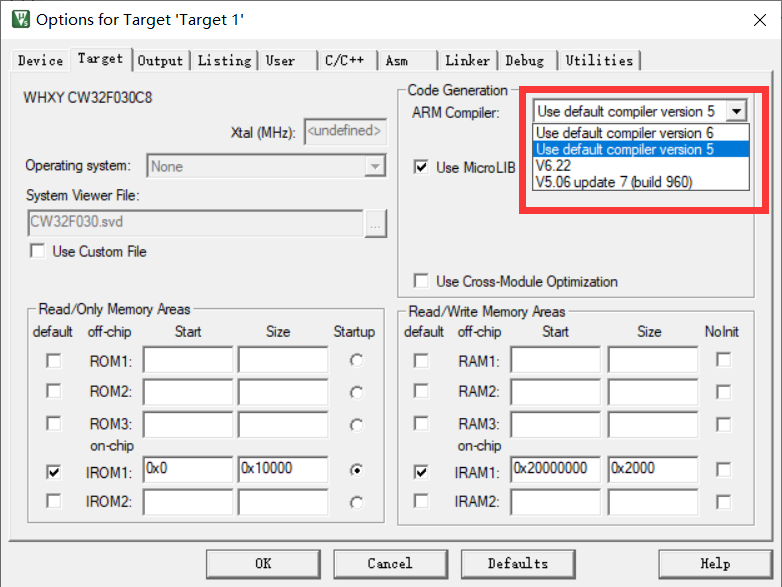
[1] The most common question in the exchange group during this training camp was about software installation. The new version of KEIL has reached version 5.40 in May 2024. The download link is no longer provided in the new version, and CMSIS has also been updated to 6.1.0. This makes it impossible to compile most official routines normally. These two parts need to be modified before compiling. (Only when installing version 5.39 is there a problem with compiler mismatch)
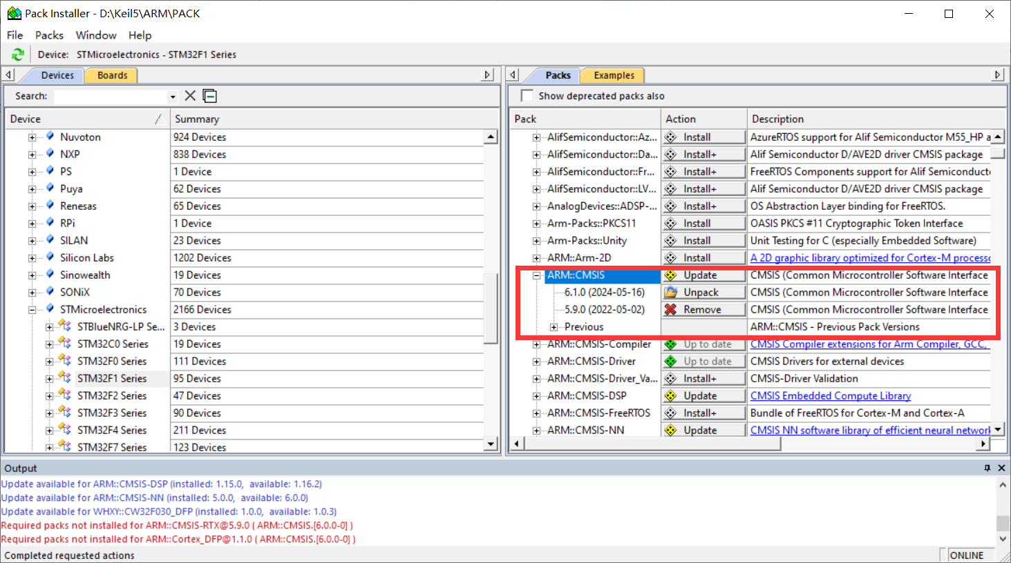
[2] At the same time, I recommend an official link for chip support package with a relatively fast download speed. From now on, you don't have to wait half a day to download in KEIL PACK Installer.
2. Program Part
Since it is the first time to come into contact with measurement programs, you must write programs yourself to understand them. After studying for so long, I feel that CV is the eternal god. Using the official routines, you can quickly implement the configuration of peripheral registers. I just learned about CW32's BLDC before, so I have some understanding of the chip.
[1] The layout of the digital tube was modified to facilitate wiring. As a result, the segment selection bits of the digital tube do not correspond exactly to the lower eight IO ports of the microcontroller. Therefore, the display code of the segment selection of the digital tube cannot directly display the data. So the common cathode digital tube segment selection array needs to be rearranged.
/*Original common cathode digital tube segment selection array*/
const unsigned char duanma[]={0X3F,0X06,0X5B,0X4F,0X66,0X6D,0X7D,0X07,0X7F,0X6F,0X77,0X7C,0X39,0X5E,0X79,0X71,
/*0-15*//* 0 1 2 3 4 5 6 7 8 9 10:A 11:B 12:C 13:D 14:E 15:F*/
0X00,0x40,0x09,0x6f,0x76,0x1e,0x38,0x54,0X3F,0x73,0X6D,0x78,0x3e,0x58};
/*16-29*//*16 empty 17:- 18 two 19:G 20:H 21:J 22:L 23:N 24:O 25:P 26:S 27:T 28:U 29:c*/ /
*New common cathode digital tube segment selection array*/
const uint8_t duanma[]={0XF5,0X05,0XB3,0X97,0X47,0XD6,0XF6,0X85,0XF7,0XC7,0XE7,0X76,0XF0,0X37,0XF2,0XE2,0X00,0x75};
//Common cathode digital tube segment code 0 1 2 3 4 5 6 7 8 9 ABCDEF empty V

[2] Hardware Error: Due to the use of a 220K resistor with a 5% error, there is always a significant error when measuring voltage. Therefore, the error can only be reduced through software calculation.
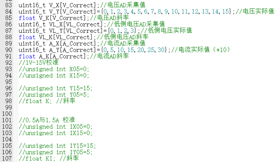
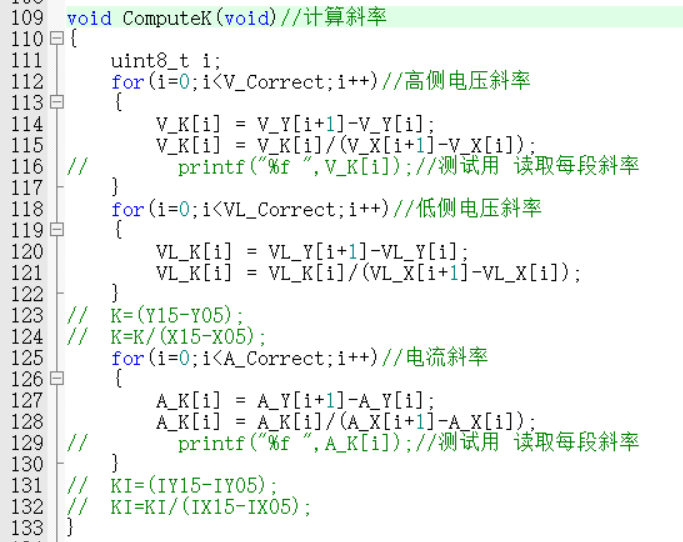
① The initial error solution was similar to the method of a linear equation in one variable. By calculating the actual value and the measured value for each segment, the error slope and zero point were calculated.
Below is a step-by-step measurement of the printed actual value and measured value through the serial port. It was found that within the measurement range of the 0-3V low-side voltage detection terminal, the data error of the high-side voltage detection terminal increases with the increase of the voltage value. (This may be a program calculation problem. If there is any error, please point it out.)
The slope calculated for each measurement point was used to back-calculate the actual value for each data point Y=KX+B. However, the workload was a bit large, so the average value of the slope was used for testing first. However, as shown in the figure below, there is still an error of tens of millivolts between the low-side voltage measurement and the high-side voltage measurement.
/*Directly calculate data (no calibration)*/
V = (float)Mean_Value_Filter(Volt_Buffer,ADC_MAXSIZE)/4096*ADC_REF_VALUE*23*100;//Uo=R2/(R1+R2)*U
V_low = (float)Mean_Value_Filter(Volt_low_Buffer,ADC_MAXSIZE)/4096*ADC_REF_VALUE*2*100;
Curr = (float)Mean_Value_Filter(Curr_Buffer,ADC_MAXSIZE)/4096*ADC_REF_VALUE*Sample_R*100;
TL431 = (float)Mean_Value_Filter(Volt_TL431_Buffer,ADC_MAXSIZE)/4096*ADC_REF_VALUE*100;

② Finally, I ported the official example program and found that it still relies on algorithms. Learning more methods is the best way to solve the problem, and it's not an insurmountable hardware error. After intermittently staring at the code for two days, I finally understood the implementation principle of the program. Therefore, I upgraded the original two-point calibration of 5V, 15V, 0.5A, and 1.5A to a step-by-step calibration of 0V-30V and 0A-3A.
I switch between three interfaces—voltage and current display, voltage calibration, and current calibration—using button 1. In the calibration interface, the digital tube displays the current calibration value at the top, and the AD measurement value is displayed below. I use button 2 to calibrate the current data. After calibration, it returns to the data display interface. Button 3 immediately returns to the data display interface. Voltage calibration requires 30 levels, and current calibration requires 6 levels. The calibration process is a bit complex, but the effect is still there. The error of 0.01V in the example program can be reduced to 0.01V error at several volts. (The accuracy can likely be further improved; further learning is needed.)

③ Export the calibration data via serial port. The data can be stored in an array and calibrated directly using buttons, avoiding accidental modification of the reference value.

V. Demonstration of Results
Voltage measurement.mp4
Current Measurement.mp4
Voltage and Current Calibration - Compressed Version.mp4
Simple Voltmeter and Ammeter.rar
PDF_Digital Voltage and Current Meter Based on CW32.zip
Altium_CW32-based Digital Voltage and Current Meter.zip
PADS_CW32-based Digital Voltage and Current Meter.zip
BOM_Digital Voltage and Current Meter Based on CW32.xlsx
93100
Voltage and current
This beginner's training camp project teaches how to use the CW32 development board to collect and display voltage and current data.
1. For the hardware part, watching the videos from experienced programmers and following the schematics, along with the BOM components, to design the board was very helpful, especially in component selection and circuit routing. I initially wanted to directly use chips to replace the development board, but I followed the training camp's requirements and used the development board. 2. The software part was too difficult for a beginner; setting up the Keil environment took two days, and I only managed to get it working with remote support from an experienced programmer. However, learning how to program the ST microcontroller for CW32 was quite helpful.
I directly programmed Experiment Nine, but I still don't understand calibration. I'll submit it as open source first and continue learning.
Finally, here's a power-on video.
Video demonstration.mp4
PDF_Voltage Current.zip
Altium_voltage_current.zip
PADS_Voltage Current.zip
BOM_Voltage and Current.xlsx
93101
AI_BS21-32S Starlight Core Board
The core board was designed using the Aisinco AI-BS21 Star Flash module, with I/O pins for easy functional testing.
This BS21-32S module core board is designed based on the Ai-BS21-32S-Kit development board. It has an additional USB port for automatic firmware download. It has one onboard LED and one button that can be used freely. The resistors and capacitors are packaged in 0402. Datasheets can be found on the Ai-BS21-32S-Kit website
. The actual product image
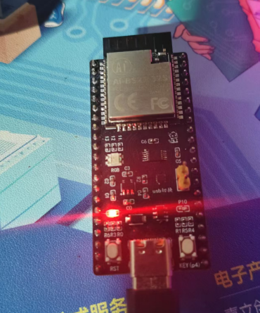
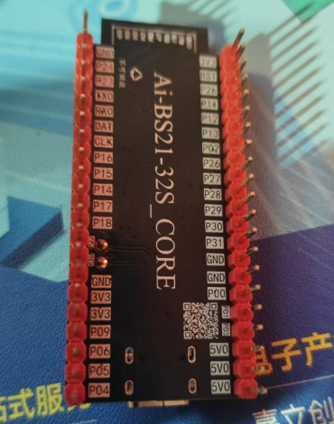
has been verified in engineering. The BOM may be inaccurate, so it is recommended to refer to the schematic diagram.
PDF_AI_BS21-32S Starlight Core Board.zip
Altium_AI_BS21-32S Starlight Core Board.zip
PADS_AI_BS21-32S Starlight Core Board.zip
BOM_AI_BS21-32S Starlight Core Board.xlsx
93102
Old Wang's 1.2-inch 240*240 IPS screen adapter board
Old Wang 1.2IPS Adapter Board
Based on the link [Taobao] https://m.tb.cn/h.5uDm2xSNlWCnj1w?tk=uH5hWlALoDM CZ3452 "Disassembled 1.2-inch 240x240 color IPS screen with silicone protective case, refurbished, no information available". Clicking the link or searching on Taobao will open the page directly.
This screen has slight color distortion; it's not recommended.
Revision history:
20240815 - Moved the stand one millimeter to the left.
idlefish-msg-1709282424229.mp4
PDF_Old Wang 1.2-inch 240-inch IPS Screen Adapter Board.zip
Altium_Old Wang 1.2-inch 240-inch IPS screen adapter board.zip
PADS_Old Wang 1.2-inch 240-inch IPS screen adapter board.zip
BOM_Old Wang 1.2-inch 240-inch IPS Screen Adapter Board.xlsx
93103
electronic


 京公网安备 11010802033920号

 923-2A1E-D1E


