I. Project Introduction
I have always been a lighting fanatic, proficient in lighting LEDs and digital tubes, but I have never been familiar with measurement programs. In this training camp, I made a simple digital voltage and current meter using the LCSC Skystar CW32 development board to try to learn the methods of measurement and reading between circuits. Thanks to LCSC for letting me experience the powerful one-stop service again. Through this project, I gained a deeper understanding of functions such as color screen printing, 3D printing, and panel making.


II. Hardware Part
1. Power Supply Step-Down Circuit

The power supply is provided by the SE8550K2, a low dropout linear regulator that can support a maximum input of 40V. Since the project does not require a large current, an LDO step-down is used.
[1] The schematic diagram not only shows the pin connections of each component, but also indicates the current flow direction in the circuit design. First, low-frequency filtering is done through electrolytic capacitors, and then high-frequency noise is filtered out through small-capacity capacitors.
[2] When designing the DC plug, attention should be paid to the inner diameter of the DC socket. Common ones are DC2.1 and DC2.5. Make sure that the power connector and DC socket are suitable.
[3] The reverse connection protection design uses Schottky diodes (metal + semiconductor), with a low forward voltage of 0.2V-0.3V, suitable for fast switching and low voltage drop. Common models are SS14 and 1N5819. The easily confused switching diode is a typical PN junction, with a voltage drop of 0.6V-1.0V, suitable for digital and pulse circuits. Common model is 1N4148.
[4] Overcurrent protection and short circuit protection can be effectively achieved by connecting a 10R resistor in series in the circuit. The common power of 0603 package resistors is mainly 100mW. P=UI=I²R. After overcurrent, the resistor burns out to prevent damage to subsequent circuits.
2. Voltage sampling circuit

[1] The common battery voltage sampling circuit is similar to the low-side voltage circuit on the right. It collects the external voltage by dividing the voltage equally between two 10K resistors. U=AD/4096×Vref×2
【2】The high-side voltage sampling circuit uses a 220K+10K resistor to divide the voltage, U=(R/Rtotal)xUsource-->U_ADC=10K/(220K+10K)×Vmeasured. Since the reference voltage is 1.5V, the maximum measurable voltage is 34.5V. U=AD/4096×Vref×(220K+10K)/10K
【3】Through diode forward clamping, when the measured voltage is too large, the pin voltage is forced to clamp to 5V+ voltage drop to prevent chip pin damage. Detailed explanation of diode clamping circuit and limiting circuit
3. Current sampling circuit
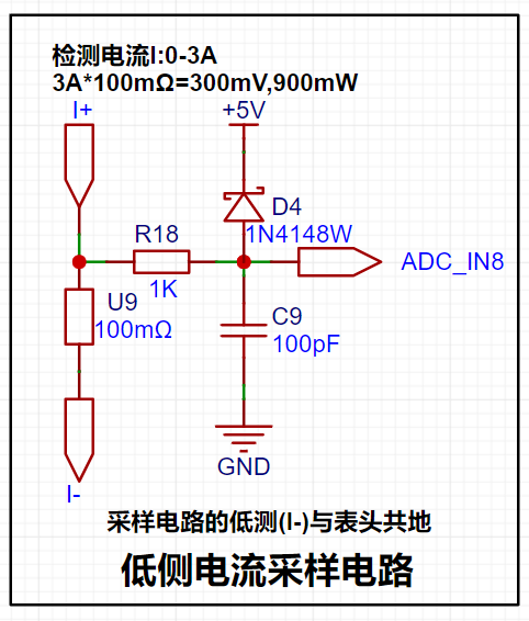
【1】The current is collected through a 100mR sampling resistor. The project design range is 0-3A, P=I²R-->9×100mR=900mW, so the power should be selected from the common 1W package resistor.
[2] The circuit uses direct pin connection and does not use a current sensing amplifier, so the voltage amplification factor is 1. I=U/R, and the measured current is calculated from the value collected by the ADC pin: I=AD value/collection range×reference voltage/sampling resistor-->I=AD/4096×Vref×10
[3] A 1K resistor is connected in series to limit the current and prevent damage to the ADC pin, and it forms an RC low-pass filter with the back-end capacitor to reduce high-frequency noise.
[4] The sampling resistor should be connected in Kelvin during layout.
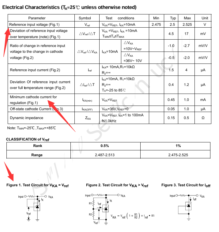
4. The TL431 reference voltage
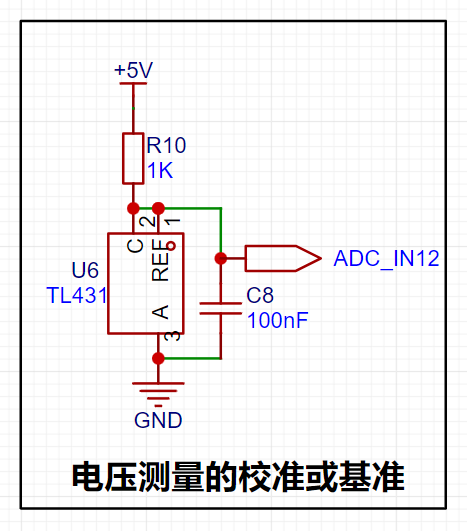
is provided by using the TL431 circuit to provide a 2.5V reference voltage (approximately 2.48V in actual measurement). According to the chip datasheet, when pins 1 and 2 of the chip are connected, VKA=VREF.
The recommended maximum current for IKA is 1mA, and the current limiting resistor R=(5V-2.5V)/0.001A=2.5K. However, the chip sink current can reach 100mA with little damage.
*For example, P=UI=2.5V100mA=0.25W, so the current limiting resistor should be a power resistor with a power greater than 0.25W. **
5. Display and operation circuit

[1] Since the chip I/O often has a sinking current capability greater than a pulling current capability, the LED is designed to be active low level (bright). In order to reduce the current consumption of the LED, some LED brightness is abandoned, the types of device parameters are reduced, and the current limiting resistor of the LED is selected as 10K. The maximum forward current of the red LED is 20mA, and the minimum resistance is R=(5V-1.5V)/I=175Ω; I=U/R->3.5V/10K=0.35mA LED current limiting resistor analysis
[2] Two 0.28-inch three-digit common cathode digital tubes are used for data display. According to the datasheet, the maximum driving current of the digital tube is 35mA, the driving voltage is 2.7V-2.9V, the microcontroller IO port can output 3.3V level, the maximum sink current input is 25mA, R=U/I-->3.3V/0.025A=132Ω. Therefore, a 300R resistor->3.3V/300R=11mA can be used to light up the digital tube.

!! After searching around, it seems that only this chip with a relatively small current was found. (rough search) !!

III. Physical Production
[1] Most of the circuit uses 0603 package. First, solder the surface mount part, and then solder the through part.
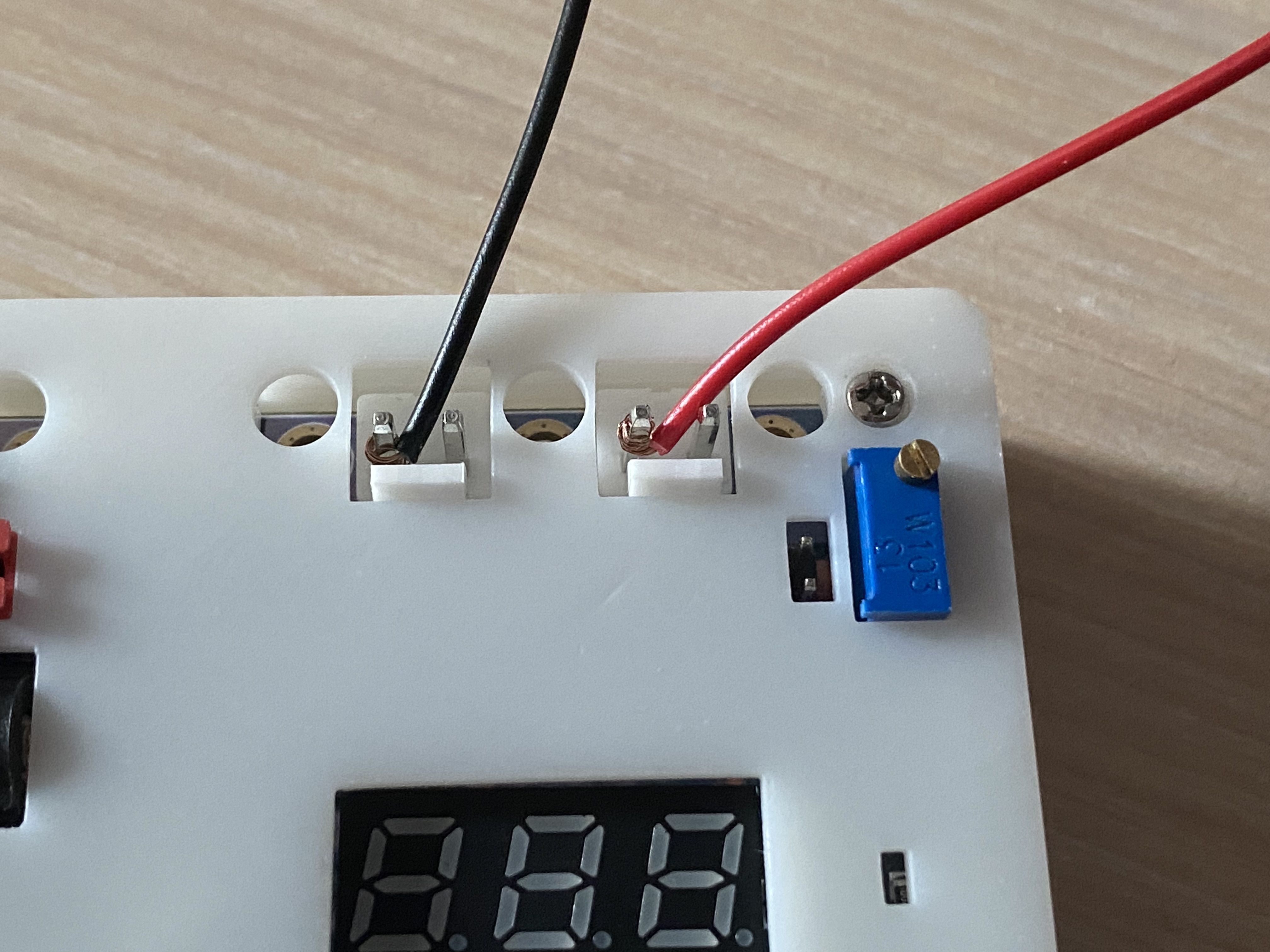
[2] If you want to use the 3.96mm×2P wire-to-board pin header for convenience, you can replace it with a 2.54mm×2P header to connect the commonly used DuPont wires, but the overcurrent capacity will affect the measurement range. (This time, DuPont wire was directly wrapped around the terminal block for easy measurement)
IV. Software Part
1. Compiler Part
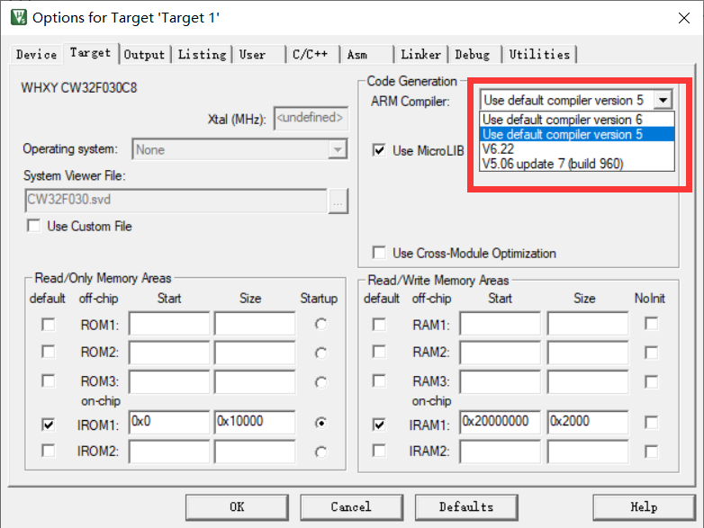
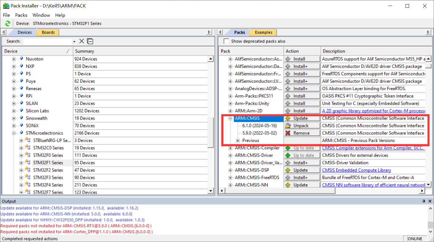
[1] The most common question in the exchange group during this training camp was about software installation. The new version of KEIL has reached version 5.40 in May 2024. The download link is no longer provided in the new version, and CMSIS has also been updated to 6.1.0. This makes it impossible to compile most official routines normally. These two parts need to be modified before compiling. (Only when installing version 5.39 is there a problem with compiler mismatch)
[2] At the same time, I recommend an official link for chip support package with a relatively fast download speed. From now on, you don't have to wait half a day to download in KEIL PACK Installer.
2. Program Part
Since it is the first time to come into contact with measurement programs, you must write programs yourself to understand them. After studying for so long, I feel that CV is the eternal god. Using the official routines, you can quickly implement the configuration of peripheral registers. I just learned about CW32's BLDC before, so I have some understanding of the chip.
[1] The layout of the digital tube was modified to facilitate wiring. As a result, the segment selection bits of the digital tube do not correspond exactly to the lower eight IO ports of the microcontroller. Therefore, the display code of the segment selection of the digital tube cannot directly display the data. So the common cathode digital tube segment selection array needs to be rearranged.
/*Original common cathode digital tube segment selection array*/
const unsigned char duanma[]={0X3F,0X06,0X5B,0X4F,0X66,0X6D,0X7D,0X07,0X7F,0X6F,0X77,0X7C,0X39,0X5E,0X79,0X71,
/*0-15*//* 0 1 2 3 4 5 6 7 8 9 10:A 11:B 12:C 13:D 14:E 15:F*/
0X00,0x40,0x09,0x6f,0x76,0x1e,0x38,0x54,0X3F,0x73,0X6D,0x78,0x3e,0x58};
/*16-29*//*16 empty 17:- 18 two 19:G 20:H 21:J 22:L 23:N 24:O 25:P 26:S 27:T 28:U 29:c*/ /
*New common cathode digital tube segment selection array*/
const uint8_t duanma[]={0XF5,0X05,0XB3,0X97,0X47,0XD6,0XF6,0X85,0XF7,0XC7,0XE7,0X76,0XF0,0X37,0XF2,0XE2,0X00,0x75};
//Common cathode digital tube segment code 0 1 2 3 4 5 6 7 8 9 ABCDEF empty V

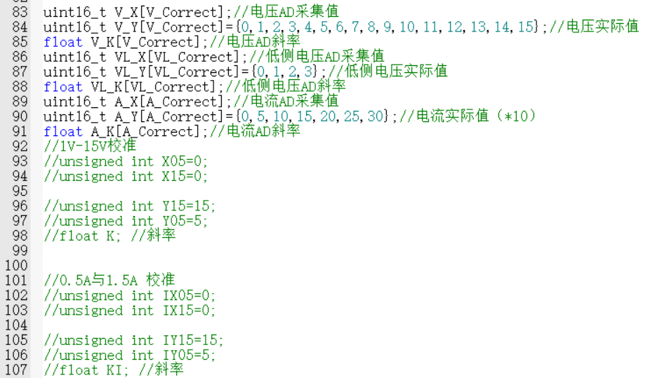
[2] Hardware Error: Due to the use of a 220K resistor with a 5% error, there is always a significant error when measuring voltage. Therefore, the error can only be reduced through software calculation.
① The initial error solution was similar to the method of a linear equation in one variable. By calculating the actual value and the measured value for each segment, the error slope and zero point were calculated.
Below is a step-by-step measurement of the printed actual value and measured value through the serial port. It was found that within the measurement range of the 0-3V low-side voltage detection terminal, the data error of the high-side voltage detection terminal increases with the increase of the voltage value. (This may be a program calculation problem. If there is any error, please point it out.)
The slope calculated for each measurement point was used to back-calculate the actual value for each data point Y=KX+B. However, the workload was a bit large, so the average value of the slope was used for testing first. However, as shown in the figure below, there is still an error of tens of millivolts between the low-side voltage measurement and the high-side voltage measurement.
/*Directly calculate data (no calibration)*/
V = (float)Mean_Value_Filter(Volt_Buffer,ADC_MAXSIZE)/4096*ADC_REF_VALUE*23*100;//Uo=R2/(R1+R2)*U
V_low = (float)Mean_Value_Filter(Volt_low_Buffer,ADC_MAXSIZE)/4096*ADC_REF_VALUE*2*100;
Curr = (float)Mean_Value_Filter(Curr_Buffer,ADC_MAXSIZE)/4096*ADC_REF_VALUE*Sample_R*100;
TL431 = (float)Mean_Value_Filter(Volt_TL431_Buffer,ADC_MAXSIZE)/4096*ADC_REF_VALUE*100;

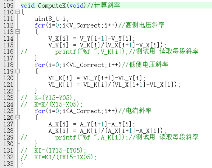
② Finally, I ported the official example program and found that it still relies on algorithms. Learning more methods is the best way to solve the problem, and it's not an insurmountable hardware error. After intermittently staring at the code for two days, I finally understood the implementation principle of the program. Therefore, I upgraded the original two-point calibration of 5V, 15V, 0.5A, and 1.5A to a step-by-step calibration of 0V-30V and 0A-3A.
I switch between three interfaces—voltage and current display, voltage calibration, and current calibration—using button 1. In the calibration interface, the digital tube displays the current calibration value at the top, and the AD measurement value is displayed below. I use button 2 to calibrate the current data. After calibration, it returns to the data display interface. Button 3 immediately returns to the data display interface. Voltage calibration requires 30 levels, and current calibration requires 6 levels. The calibration process is a bit complex, but the effect is still there. The error of 0.01V in the example program can be reduced to 0.01V error at several volts. (The accuracy can likely be further improved; further learning is needed.)

③ Export the calibration data via serial port. The data can be stored in an array and calibrated directly using buttons, avoiding accidental modification of the reference value.

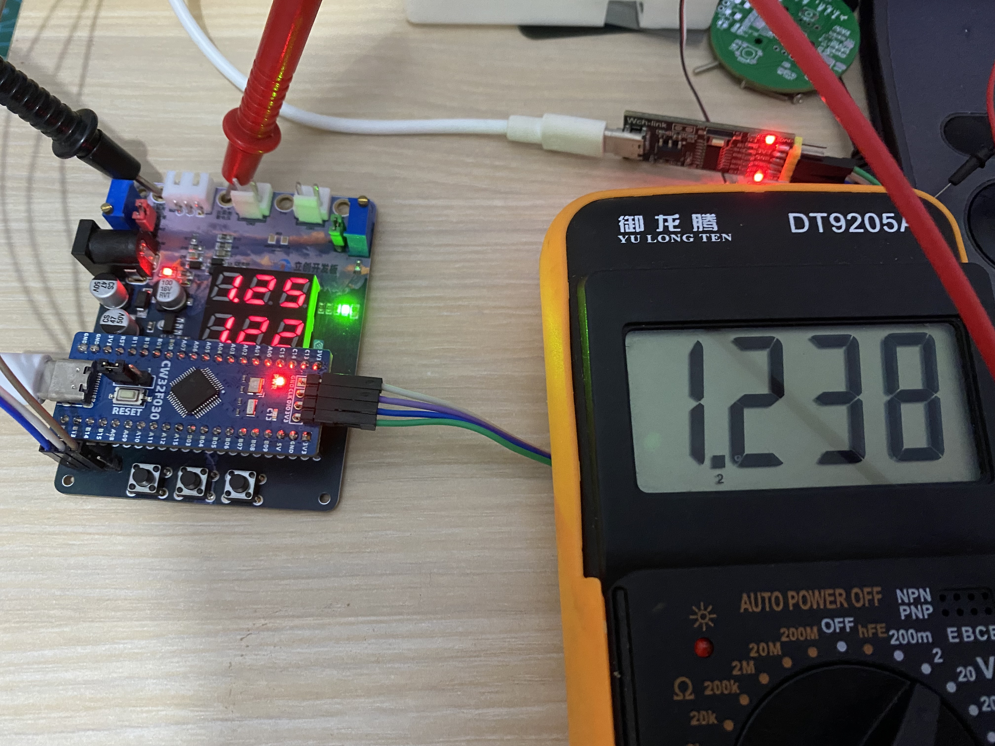
V. Demonstration of Results


 京公网安备 11010802033920号

 VI-J20EY


