I. Introduction to the SkyStar Development Board:
SkyStar Development Board Schematic Diagram:

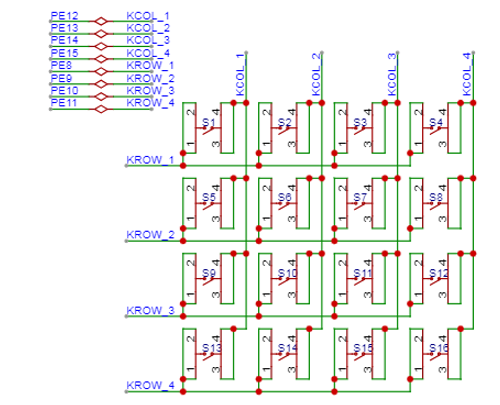
II. Matrix
Keyboard: The basic structure of a matrix keyboard includes keys, row pins, and column pins. Keys are generally mechanical or touch keys. Row and column pins are connected to the rows and columns of the matrix keyboard, respectively, to detect the input status of the keys.
III. Buzzer
Schematic Diagram:

IV. Vibration Motor
Schematic Diagram:

V. Digital Tube
Schematic Diagram:

VI. Independent Key
Schematic Diagram:

VII. Screen :
This learning expansion board has two screen interfaces, which are not shown due to budget constraints. Those interested can try it out themselves.
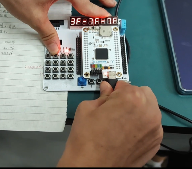
VIII. Physical Demonstration
: Photos of the actual product are provided, with captions added.
9. Experimental case
digital tube code implementation:
#include "gd32f4xx.h"
#include "systick.h"
#include
#include "main.h"
#include "LED.h"
#include "USART.h"
#if 1
#define GET_BIT_VAL(byte, pos) (byte &
(1 << pos))
#define NOP_TIME() __NOP();__NOP()
#define NIXIE_DI_RCU
RCU_GPIOD
#define NIXIE_DI_PORT GPIOD
#define NIXIE_DI_PIN
GPIO_PIN_0
#define NIXIE_SCK_RCU
RCU_GPIOD
#define NIXIE_SCK_PORT GPIOD
#define NIXIE_SCK_PIN GPIO_PIN_4
#define NIXIE_RCK_RCU
RCU_GPIOD
#define NIXIE_RCK_PORT GPIOD
#define NIXIE_RCK_PIN
GPIO_PIN_1
#define NIXIE_DI(bit)
gpio_bit_write(NIXIE_DI_PORT, NIXIE_DI_PIN,
bit ? SET : RESET) // Data input
#define NIXIE_SCK(bit)
gpio_bit_write(NIXIE_SCK_PORT,
NIXIE_SCK_PIN, bit ? SET : RESET) // Shift register
#define NIXIE_RCK(bit)
gpio_bit_write(NIXIE_RCK_PORT,
NIXIE_RCK_PIN, bit ? SET : RESET) // Latch register
void nixie_init() {
rcu_periph_clock_enable(NIXIE_DI_RCU);
gpio_mode_set(NIXIE_DI_PORT, GPIO_MODE_OUTPUT, GPIO_PUPD_NONE, NIXIE_DI_PIN);
gpio_output_options_set(NIXIE_DI_PORT, GPIO_OTYPE_PP, GPIO_OSPEED_MAX, NIXIE_DI_PIN);
rcu_periph_clock_enable(NIXIE_SCK_RCU);
gpio_mode_set(NIXIE_SCK_PORT, GPIO_MODE_OUTPUT, GPIO_PUPD_NONE, NIXIE_SCK_PIN);
gpio_output_options_set(NIXIE_SCK_PORT, GPIO_OTYPE_PP, GPIO_OSPEED_MAX, NIXIE_SCK_PIN);
rcu_periph_clock_enable(NIXIE_RCK_RCU);
gpio_mode_set(NIXIE_RCK_PORT, GPIO_MODE_OUTPUT, GPIO_PUPD_NONE, NIXIE_RCK_PIN);
gpio_output_options_set(NIXIE_RCK_PORT, GPIO_OTYPE_PP, GPIO_OSPEED_MAX, NIXIE_RCK_PIN);
}
static void nixie_out(uint8_t dat) {
// char unsigned, need to check Plain Char is Signed or use int8_t, signed char
int8_t i;
// 8 bits, the first bit sent out will be the high bit
for(i = 7; i >= 0; i--){ // 0 to turn on
NIXIE_DI(GET_BIT_VAL(dat, i));
// Register shift operation
NIXIE_SCK(0);
NOP_TIME(); // Sleep for a while
NIXIE_SCK(1);
NOP_TIME(); // Sleep for a while
}
}
static void rck_ACTION() {
NIXIE_RCK(0);
NOP_TIME();
NIXIE_RCK(1);
NOP_TIME();
}
void nixie_show(uint8_t a_dat, uint8_t b_idx) {
// Display 7.
// 0111 1000
// Send letter bits first (controls the content to be displayed) // 0 lights up
// 8 bits, the first bit sent out will be the high bit
nixie_out(a_dat);
// 0,1,2,3....7
// Send number bits next (controls which ones to display) // As long as it's not 0, it's high level
// 1111 1011
// 7.7. Empty 7. 7.7.7.7. ------------------- is the opposite of binary
// 8 bits, the first bit sent out will be the high bit
nixie_out(b_idx);
// Latch operation
rck_ACTION();
}
#endif
int main(void)
{
systick_config();
USART_INIT();
//led_gpio_init();
nixie_init();
nixie_show(0x00,0xff);
while(1) {
}
}
X. Demonstration
The specific demonstration is as follows:


 京公网安备 11010802033920号

 240-0323-21SCG8J2-18R


