I. Main Functions
1. Picks up external audio sources via an I2S microphone, performs FFT transformation, and drives the TFT display and WS2812B LED board for music spectrum display. Spectrum mode, sensitivity, and brightness can be adjusted via buttons.
2. Creates images on a 16*16 pixel canvas via the TFT and touchscreen, and displays them on the WS2812B LED board.
3. Decodes MP3 files and outputs them to the I2S amplifier circuit for audio playback.
II. Circuit Design
1. The main control uses the ESP32-WROOM-32 module, which is easy to solder. Furthermore, the ESP32 supports almost all IO mappings, so there's little need to worry about IOs not working for certain functions.
2. Audio input uses an I2S microphone; here, the ICS43434 is used, which is much more sensitive than the previously used INM441.
3. Audio output uses the NS4168 chip, which supports I2S and can drive a maximum 4-ohm 2.5W speaker. The main reasons for choosing this chip are: 1. Simple soldering of the 8-pin chip, fewer external components, and easy integration onto the board;
2. Audio playback files are stored on an SD card and connected to the main controller via an SPI interface;
3. The resistive touchscreen and TFT are connected to the main controller via a shared SPI interface;
4. A five-way joystick button is connected to IO034353639 to implement button control function;
5. An LED is used to indicate the power status;
6. A tactile switch is used to reset the system;
7. An automatic download circuit is designed using CH340C for easy development;
8. The power supply uses TYPE-C for direct 5V supply, and the onboard AMS1117 provides 3.3V power;
9. Considering the free prototyping size, a 65mm*65mm LED board was designed, which can be used to panelize four boards.

III. Program Design
The program uses Arduino IDE
. 1. The interaction method combines touchscreen and button input (touchscreen sampling affects the main process). The touchscreen and TFT share VSPI.
2. The SD card module uses HSPI independently.
3. The I2S microphone and I2S amplifier chip use independent I/O interfaces, each occupying 3 I/O pins.
IV. Appearance Design
The casing uses LCSC EDA design. It consists of a lamp board casing and a main control casing. The main control casing can be directly embedded into the back of the lamp board casing, making it a single unit. The front panel of the lamp board uses LCSC's panel. Below is a picture of the actual product. Due to the reversed grid offset and antenna hole positions mentioned later, the picture below is not a single unit.
The main control unit, housing

, light board, panel light board, and main control unit

are combined. V. Function demonstration (see video below). VI. Existing problems : 1. The audio output chip enable pin is directly connected to the VBUS input. Therefore, when this module is not used, there may be speaker noise and power consumption issues. If the TFT backlight control is not used later, the above pins can be used to enable the NS4168. 2. In the first version of the design, only pins 34, 35, 36, and 39 were mentioned as input pins, so they were used for button control. It was found that these pins did not have pull-up resistors, causing the button reading to always be low voltage. This was solved by using jumper wires, and the circuit diagram was upgraded by adding pull-up resistors. 3. Considering the limited board space, the TFT used has a soldered interface, but incomplete soldering can easily lead to malfunctions in the touch function. The PCB board can be used to press down the FPC for soldering to prevent cold solder joints. 4. Two problems were also encountered in the housing design. One issue is that the assembly tolerance in the design of the light board housing is too small, causing the light board to be unable to fit into the light board grille. This can be resolved by grinding the grille holes. Another issue is that the front and back of the light board housing and the main control housing were not clearly distinguished during the design process. This resulted in the pre-drilled holes for the onboard PCB antenna on the light board housing being reversed (it should have been offset to the left, but it was offset to the right, a difference of 6mm). This prevented the main control unit from being fully inserted into the light board housing. This has been corrected in the housing design file. 5. The misalignment of the antenna holes and the use of a free font library to generate the bin file caused occasional missing MP3 file names when actually displayed.


Function 1 Demonstration.mp4
Overall demonstration.mp4
Firmware.zip
PDF_ESP32 Music Ambient Light.zip
Altium_ESP32 Music Ambient Light.zip
PADS_ESP32 Music Ambient Light.zip
BOM_ESP32 Music Ambient Light.xlsx
94273
Environmental monitoring based on 51 microcontroller
Reuse of Training Materials from Campus EDA Instructors in April
Project Overview:
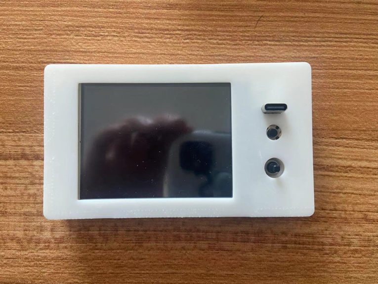
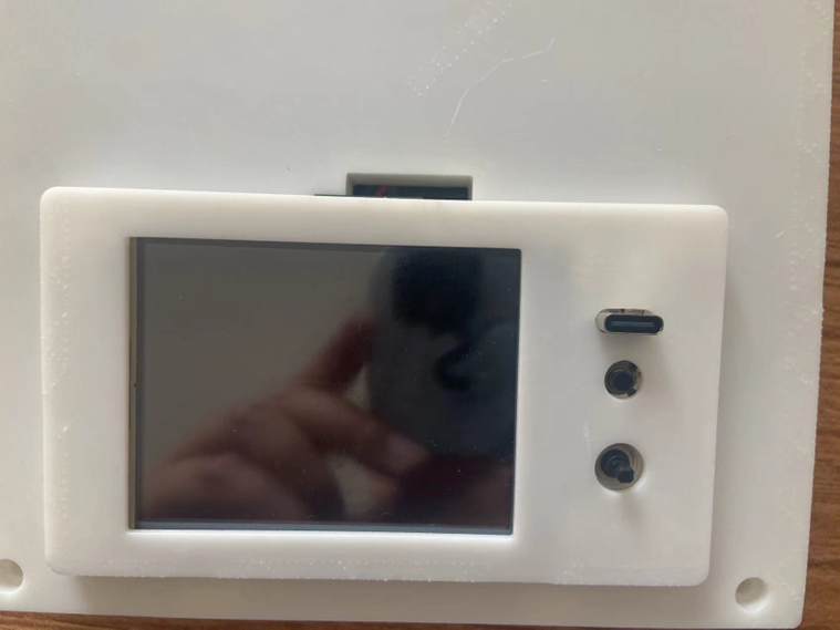
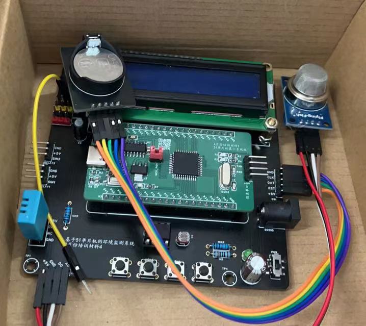
This project uses the STC89C52RC as the main control MCU to create an environmental monitoring circuit, realizing the monitoring of changes in temperature, humidity, light intensity, and smoke concentration. It also adds an LCD1602 interface and a DS1302 clock module interface, displaying the collected data on the LCD1602 and showing the time. The baseboard has two reserved 5V relay interfaces for further customization. This project adopts a design that separates the baseboard from the MCU core board, increasing circuit reusability and modular design for higher circuit reuse.
The minimum system board uses Type-C power supply and is equipped with a CH340C, enabling direct Type-C programming. The minimum system board uses pin headers and jumpers to isolate the MCU power supply; removing these disconnects powers off the MCU, allowing the 51 microcontroller to be programmed.
The baseboard uses a DC005 interface for 5V power supply, controlled by a DIP switch. The minimum system board is equipped with an AMS1117-3.3V converter to 5V, and provides three 5V and 3.3V outputs to the baseboard for future development. It is recommended to use capacitors of 220uF or higher for energy storage to prevent system malfunctions due to unstable power supply.
Two 5V relay interfaces are provided. PCB design files for the relays and DS1302 are included in the project for reference only.
The schematic
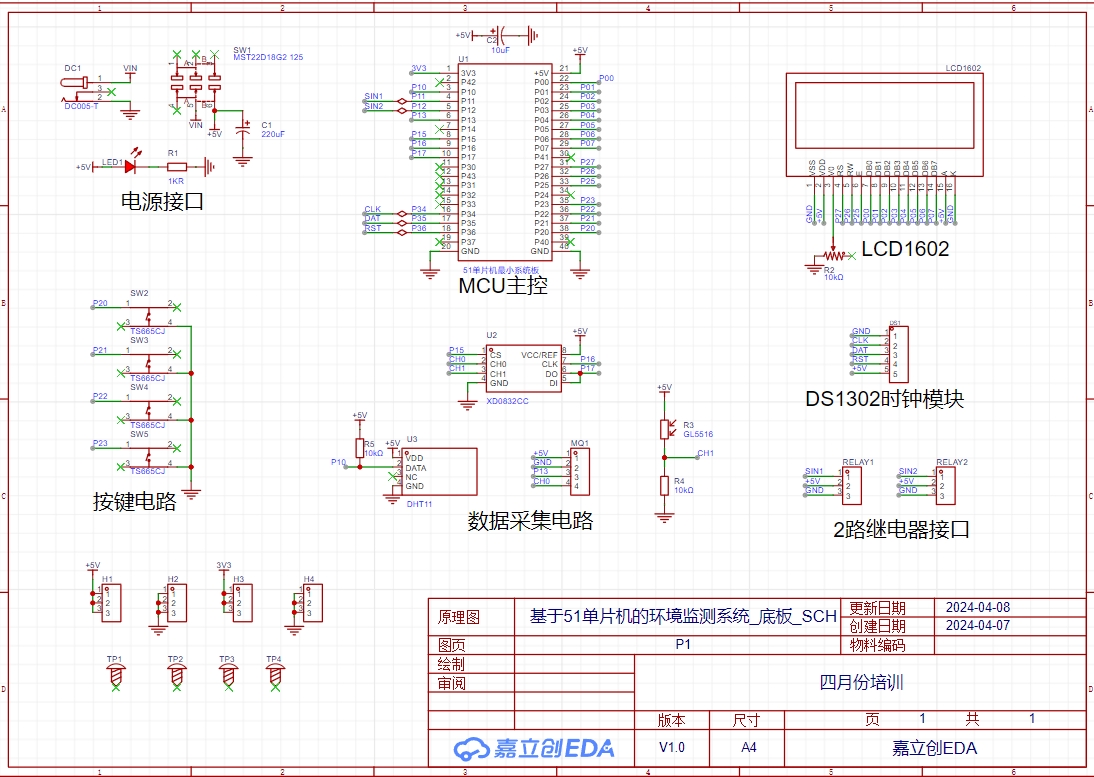
and PCB designs
comply with JLCPCB's free prototyping policy and are available for free prototyping.
The baseboard uses a two-layer layout. Considering the overall layout, the interfaces are placed on the outside, and the buttons are placed on the bottom. Power lines use 30mil, and signal lines use 15mil.
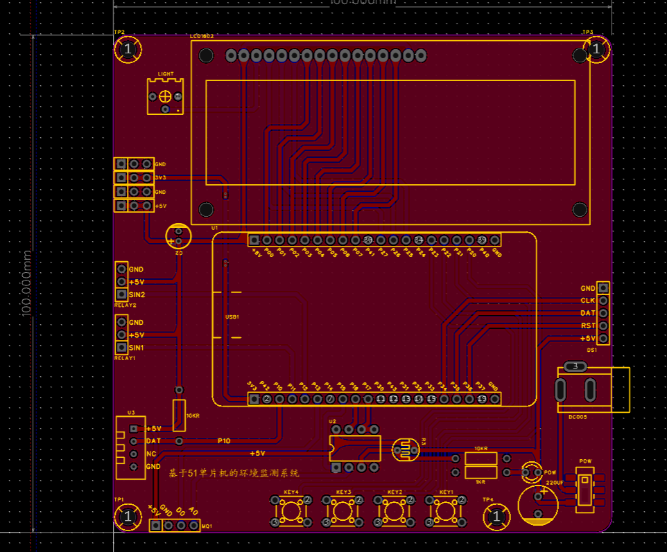

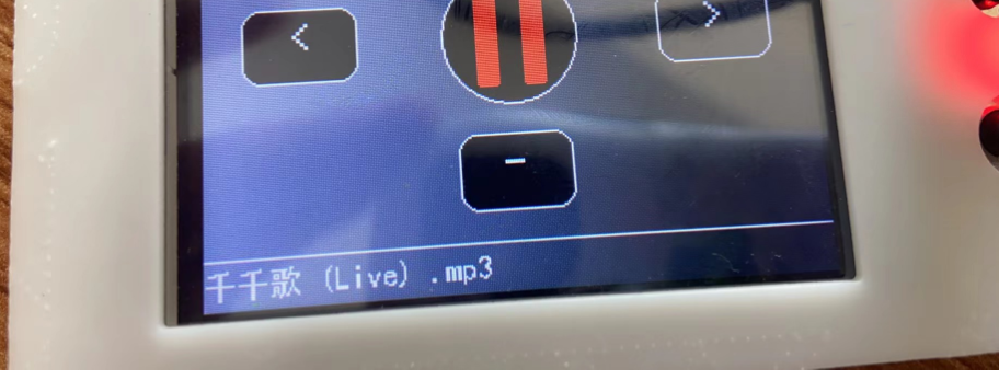
3D rendering and physical prototype

are shown.
code.hex
code(bak).zip
PDF_Environmental Monitoring Based on 51 Microcontroller.zip
Altium-based 51 microcontroller-based environmental monitoring.zip
PADS_Environmental Monitoring Based on 51 Microcontroller.zip
BOM_Environmental Monitoring Based on 51 Microcontroller.xlsx
94274
FM5010 fan plate
This is a portable fan control board based on the FM5010F, featuring three fan speeds and a 3.7V rechargeable lithium battery. It can replace the motherboard of inexpensive fans.
Note: The fan casing uses a cheap lithium battery portable fan available on Taobao. If the appearance is similar, the internal control board may be interchangeable. These fans are easy to buy.
For a demonstration video, please see https://www.bilibili.com/video/BV1g142117bJ/
Background:
Two years ago, one evening, a portable fan that was working normally suddenly started smoking...
Upon inspection, it was found that the MOSFET and diode were burnt out. Fortunately, it was discovered in time, and the dormitory smoke alarm wasn't triggered!
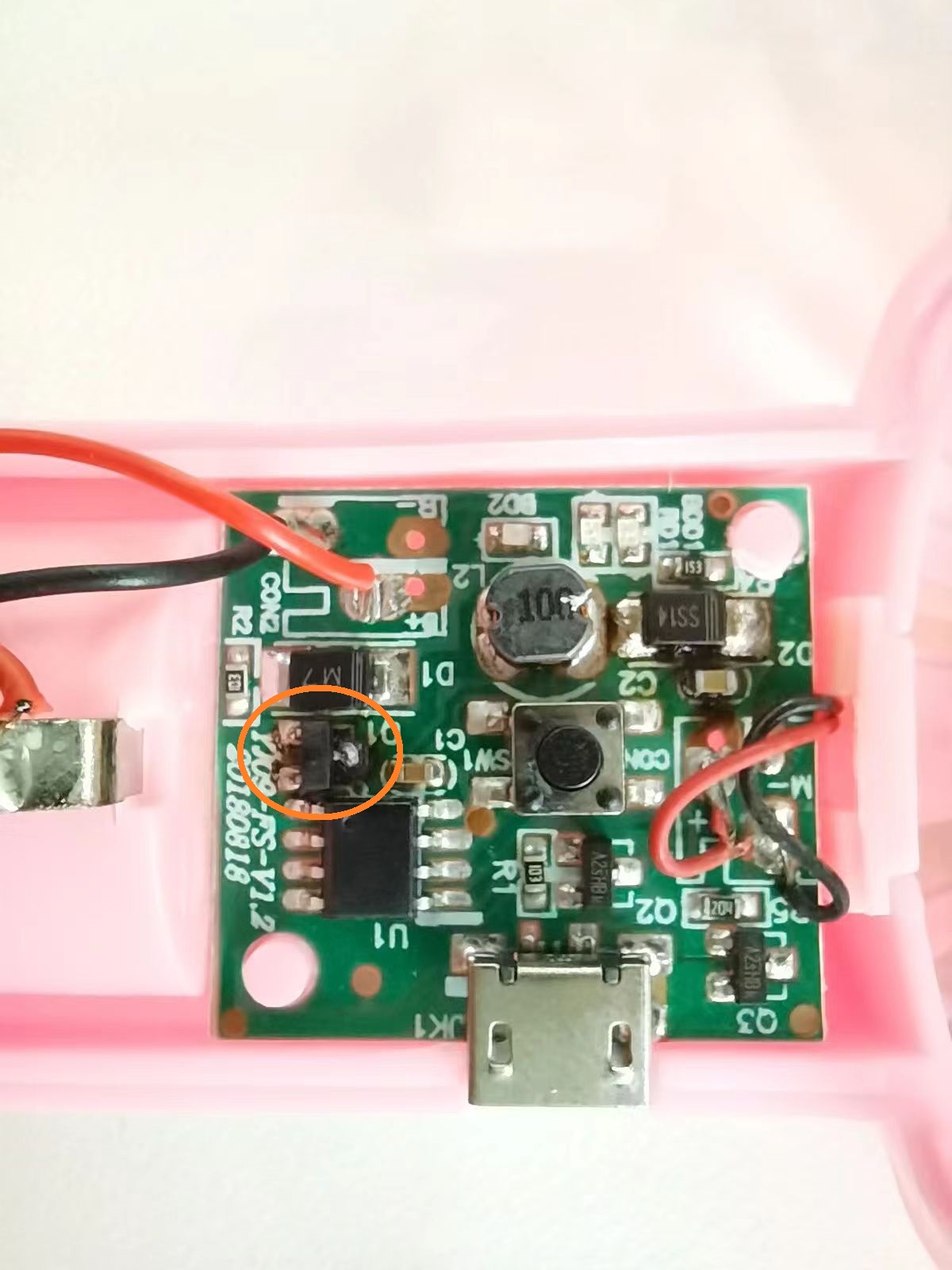
So, I decided to make a reliable control board myself using a cheap FM5010 chip. However, the first version was not only double-sided surface mount, but also had significant dimensional deviations, and it malfunctioned after a period of use, unable to control the fan's start and stop. Therefore, the fan was discarded and ended up in the electronic waste pile.
Two years later, using the same chip solution, I redesigned the driver board, and this time it was successful. The discarded fan was put back into use.

Project Introduction:
This project uses a 3.7V 18650 battery for power and uses a common portable fan casing, motor, and fan blades.
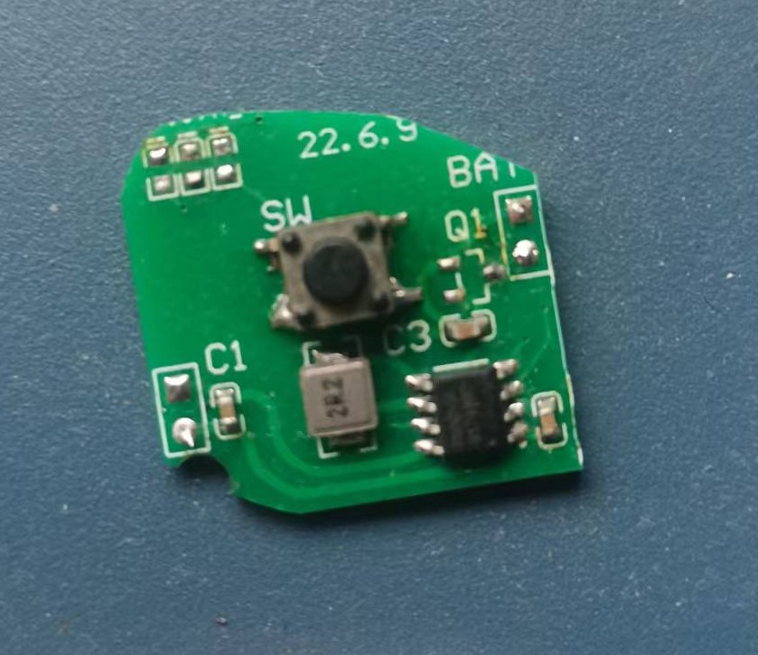
This project is based on the FM5010F chip. This chip is an integrated power IC for portable fans, integrating lithium battery charging management, three voltage output levels, and LED indicators for response status. The FM5010F discharges to drive the fan at output voltages of 4.7V, 5.5V, and 6.5V. The FM5010F features multiple protection designs, including overcurrent protection, soft-start protection, input overvoltage protection, output short-circuit protection, and chip temperature protection. It also incorporates high-performance ESD protection circuitry at the chip ports, ensuring high reliability. Therefore, the FM5010F meets the basic requirements of this project: driving the fan motor and providing multiple safety protection mechanisms to prevent malfunctions.
The FM5010F pin definitions and typical application circuit are as follows:
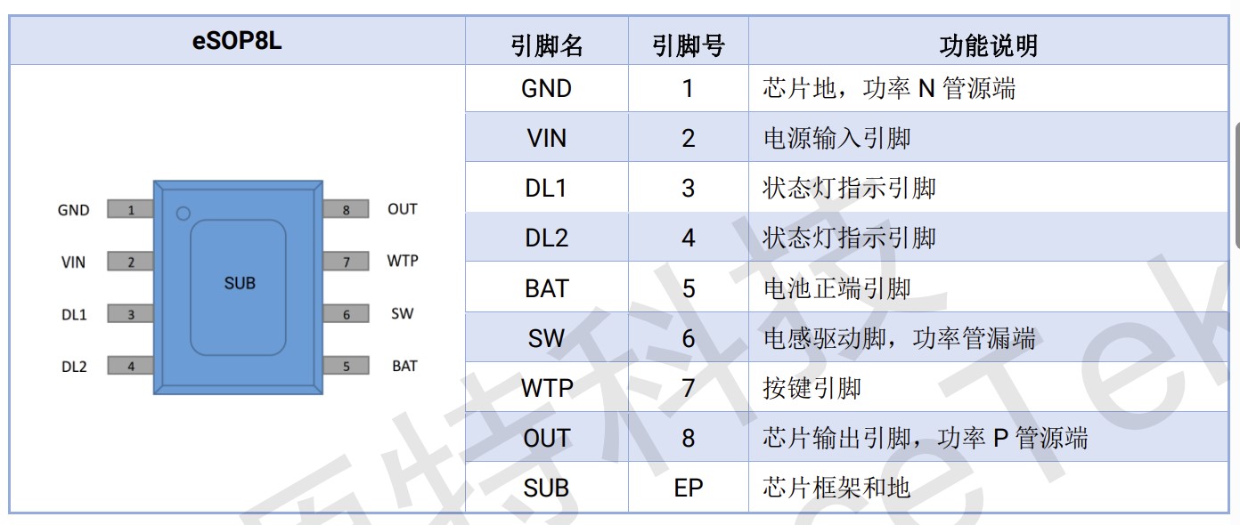
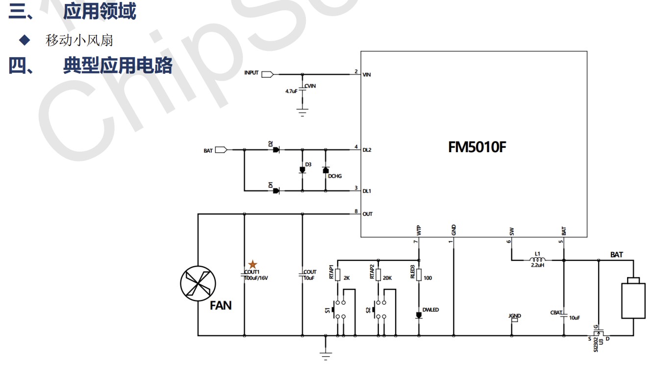
In actual use, the default function state and 2-LED display mode are adopted to simplify circuit design, reduce component costs, and shorten soldering time.


Precautions:
0. Please pay attention to the positive and negative terminals of the motor and battery during soldering!
The resistors RTAP2 and NC in the schematic diagram do not need to be soldered.
During normal operation, the indicator lights on the control board will flash.
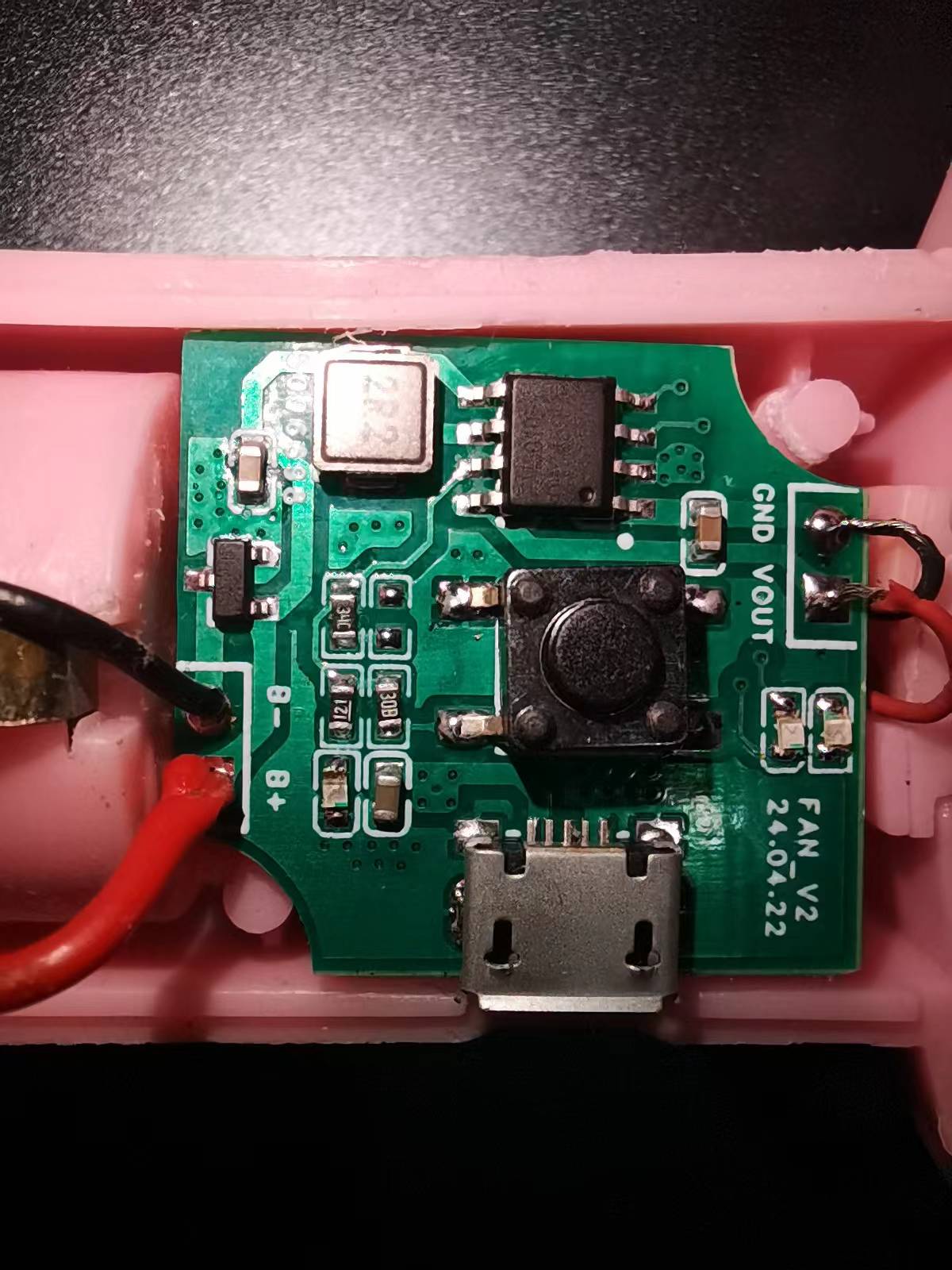
The USB port is slightly misaligned, so directly charging the 18650 battery using this driver board is not recommended. It's suggested to use a dedicated charger instead.
The inability to achieve single-sided board wiring makes this project's cost somewhat high...

WeChat_20240613112851.mp4
PDF_FM5010 Fan Plate.zip
Altium_FM5010 fan plate.zip
PADS_FM5010 fan board.zip
BOM_FM5010 Fan Board.xlsx
94275
STM32 electronic keyboard
An electronic keyboard that can play music has arrived.
1. In electronic keyboard mode, seven keys can play the notes "Do, Re, Mi, Fa, Sol, La, Si". 2. The board comes with sheet music for "Two Tigers," allowing users to play music anytime, anywhere. "Two Tigers" can also be played automatically via the user button. 3. The potentiometer adjusts the amplifier volume. 4. The circuit includes a built-in amplifier driver, providing sufficiently loud sound.

Electronic keyboard demonstration video.mp4
PDF_stm32 electronic keyboard.zip
Altium_stm32 electronic keyboard.zip
PADS_stm32 electronic keyboard.zip
BOM_stm32 electronic keyboard.xlsx
94276
Bandpass filter (300-3kHz) based on LM358
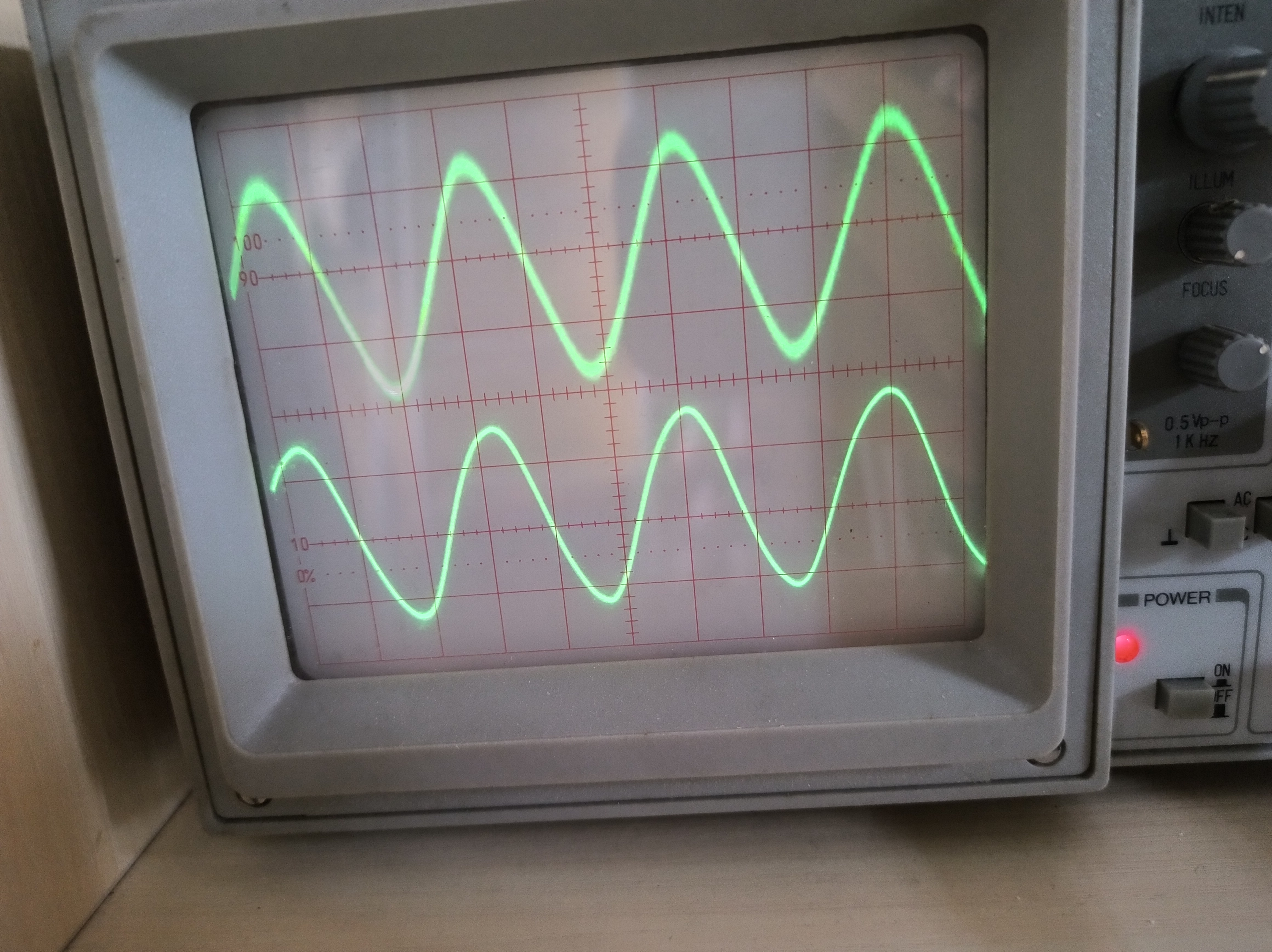
A bandpass filter based on LM358, with a passband range of 300-3kHz, has been tested and validated on a PCB.
This circuit features a single power supply, with VCC supporting 5-12V. An LM358 amplifier is used to construct a bandpass filter, combining a low-pass filter and a high-pass filter. The bandpass frequency is 3kHz and 300Hz, respectively, and the quiescent operating point is half of VCC. The corner frequency can be adjusted by changing the values of capacitors and resistors. The design allows for flexible combinations, and the circuit schematic can be modified to use positive and negative power supplies. Actual test results are shown in the figures; the top image shows the circuit before filtering, and the bottom image shows the circuit after filtering.
IMG_20240604_090148.jpg
PDF_LM358-based bandpass filter (300-3kHz).zip
Altium_LM358-based bandpass filter (300-3kHz).zip
PADS_LM358-based bandpass filter (300-3kHz).zip
BOM_LM358-based bandpass filter (300-3kHz).xlsx
94277
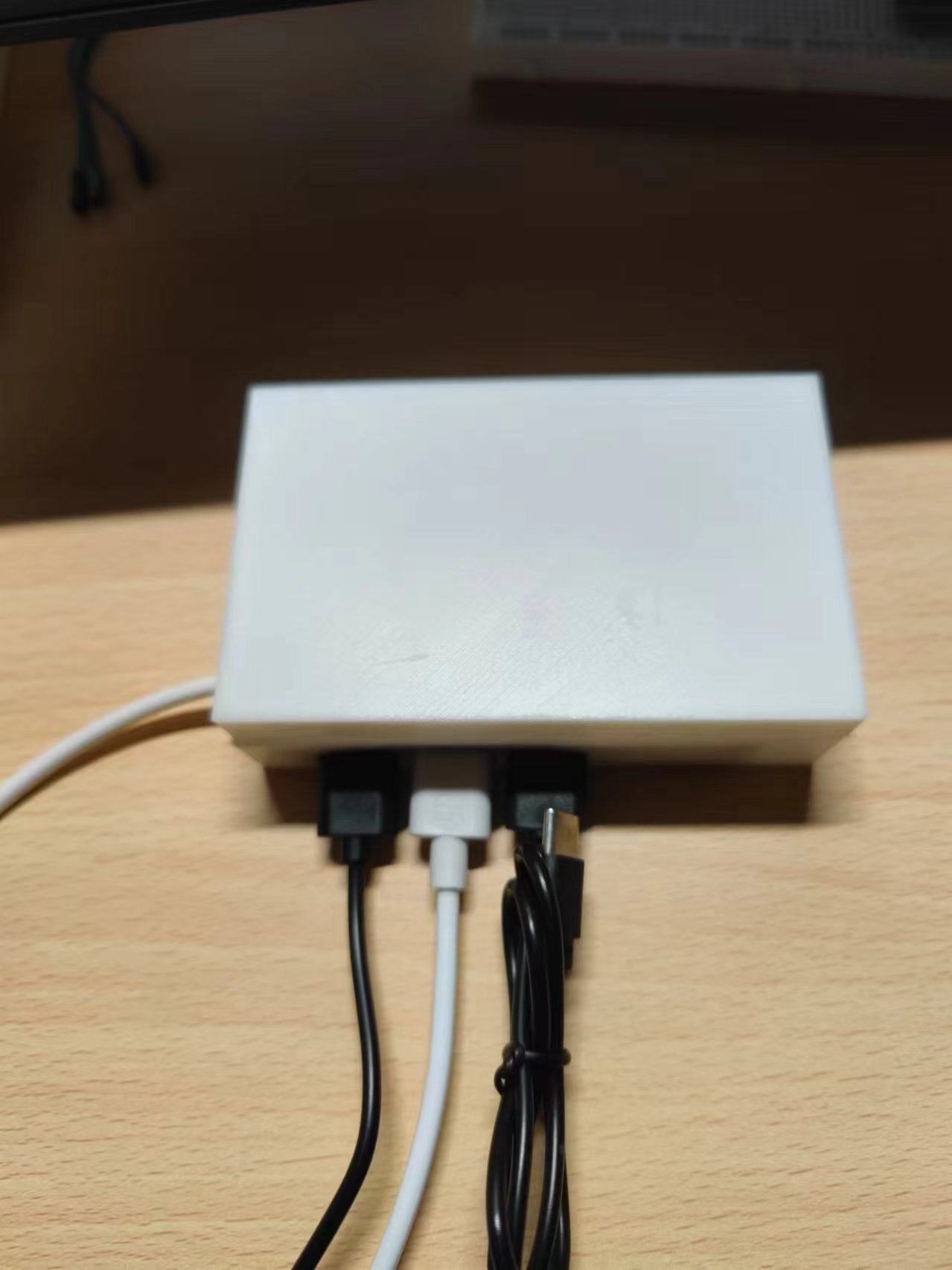
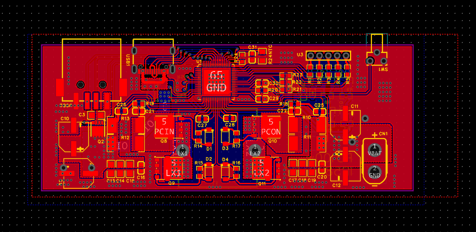
Outdoor multi-port USB expander
A multi-mouth outdoor extender
ca9eb02462fb42efe1091242c69771ed.mp4
PDF_Outdoor Multi-Port USB Extender.zip
Altium Outdoor Multi-Port USB Extender.zip
PADS Outdoor Multi-Port USB Extender.zip
BOM_Outdoor Multi-Port USB Extender.xlsx
94278
Electronic Pet Xiaodai
This mini electronic desktop pet, based on the STM32C8T6, features two control methods: Bluetooth remote control and voice recognition. It offers three output formats: body movements, facial expressions, and sound, and includes a built-in happiness and stamina calculation and reporting system. It also comes with a detachable ultrasonic obstacle avoidance module and an infrared cliff detection module.
Physical parameters: Body width approximately 7cm, length approximately 10cm (11.2cm including ultrasound), height approximately 9cm when standing upright, and approximately 6cm when lying down. This product has passed a drop test (actually, it was an accident), and dropping it from a 1m high table will not affect the pet's appearance or function.
It has a main power switch, is battery powered, and integrates charging and discharging.
Regarding the PCB design: Except for the main power switch, which is fixedly soldered, all other modules are directly plugged in via female or male headers. Areas for improvement:
1. The charging and discharging module used in this design does not have a boost function, but in practice, it has little impact on use, only affecting voice recognition wake-up when the voltage is low.
2. The four servos and the voice recognition module are connected to the same 5V power supply. When the servos operate continuously and significantly, it will affect the use of voice recognition.
For a detailed introduction, please refer to the video "[After 80 Days, We Made Our Own Electronic Pet]" https://www.bilibili.com/video/BV1kZ421p7S5/?share_source=copy_web&vd_source=c3e2fc68aa51e67bd3f2be57434d3d1c and the article on Bilibili.
misgon_cyberdog project code.zip
cyberdog-LD3320 speech recognition module project code.zip
Electronic Pet Xiaodai's Body.STL
Electronic Pet Little Dumblegs.STL
ourdog.aia
ourdog.apk
cyberdog electronic components materials.docx
PDF_Electronic Pet Xiaodai.zip
Altium_Electronic Pet Xiaodai.zip
PADS_Electronic Pet Xiaodai.zip
BOM_Electronic Pet Xiaodai.xlsx
94279
PD100W IP5389BZ A3 version
PD100W multi-protocol fast charging module, power bank
This is my first time designing a PCB for a small PD 100W multi-protocol power bank . Please provide feedback.
There are three PCB designs to suit different needs and assembly methods; you can choose whichever suits your needs. The circuitry is based on open-source solutions from the open-source forum, with some modifications. You can search for open-source solutions there. Commercial use is prohibited! The front panel is not designed; you will need to design and update it yourself. The connector is incompatible with the physical product. Surge protection circuitry has been added, and the LDO model has been changed to 5.27 for circuit optimization. It has been updated to 6.12. This is my first time designing a PCB, so please provide guidance if needed.

PDF_PD100W IP5389BZ A3 version.zip
Altium_PD100W IP5389BZ A3 version.zip
PADS_PD100W IP5389BZ A3 version.zip
BOM_PD100W IP5389BZ A3 version.xlsx
94280
electronic


 京公网安备 11010802033920号

 1111R100M00000AB


