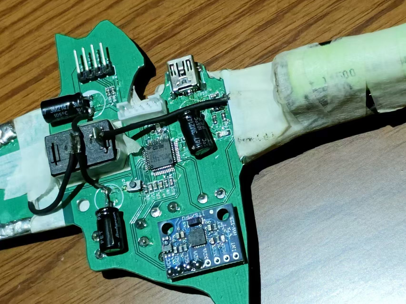
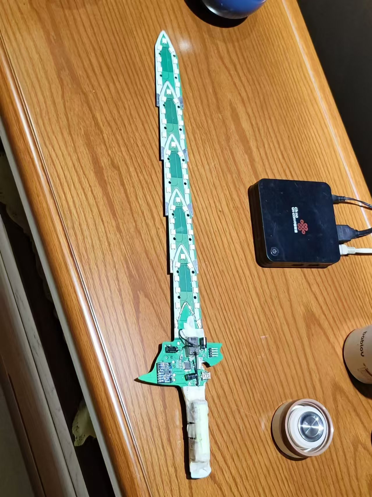
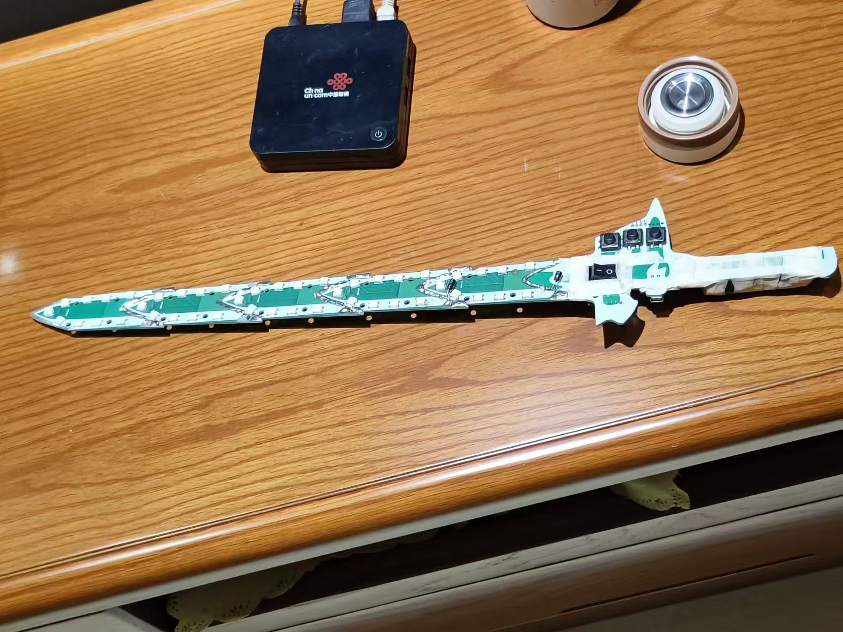
A little rant about the original project: the PCB layout of the microcontroller core board was unbearable to look at, so I redesigned it.
The sword tip layout wasn't great either, but I was too lazy to change it, so it's not a big deal.
The final result is quite good.
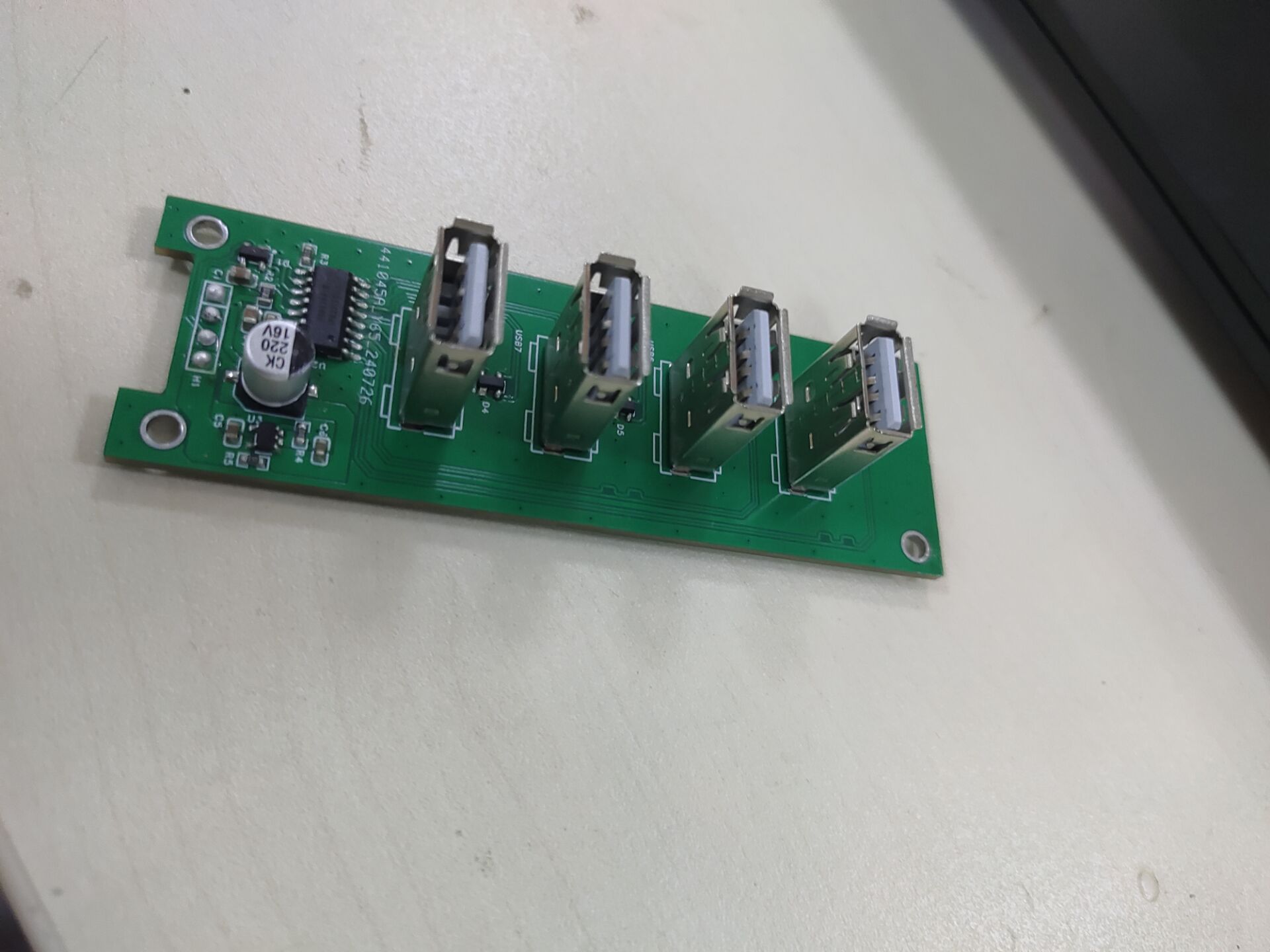
This USB 2.0 hub, built using the HS8836A, expands to 4 output ports and features short-circuit and electrostatic discharge protection.
I. General Introduction
My old docking station, which I bought for 3 yuan on Taobao, broke after only a few days. So I designed a new board myself, and it's been working perfectly for almost half a month now! This USB 2.0 hub, made using the HS8836A, expands the output to 4 ports and has short-circuit and electrostatic discharge (ESD) protection.

II. Function Introduction
1. Added ESD Protection

2. Added Short-Circuit Protection
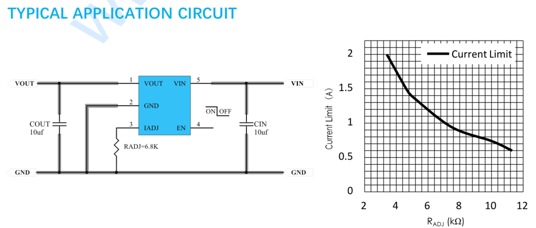
A PW1502 chip is used for current limiting, and this chip also has reverse current protection. You can adjust the protection current according to your computer's needs.
3. Circuit Principle
All circuit parts are drawn according to the recommendations in the datasheet, so please read the chip datasheet in the attachment!
Besides these components and the circuit board, you should also prepare a USB cable!
III. Summary
This hub is simple to make and inexpensive, making it very practical for debugging related projects. Its short-circuit and reverse current protection functions greatly protect our electronics enthusiasts' computers. I hope this is helpful to you!
It features a single DC input and two output channels (DC and AC), both of which can achieve constant current and constant voltage modes and have current protection functions.
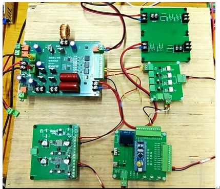
Project Description:
Single DC input, capable of outputting both DC and AC, both in constant current and constant voltage mode, with current protection.
Related Functions:
65V voltage input, outputting one DC and one AC power through a synchronous step-down circuit and inverter circuit, serving as a constant current and constant voltage source. Voltage and current are adjustable.
Project Attributes
: This is the first public release of this project; it is my original work and has not won any awards in other competitions. Project
Progress: The
hardware design is complete; after board fabrication, soldering, and debugging, the code can be entered.
Design Principle:
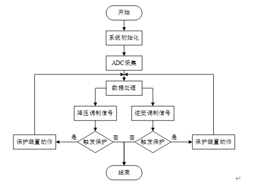
By sampling the output voltage and current signals and calculating the difference with the set voltage value, PID control is used. The PID output is the duty cycle of the switching transistor.
Software Description:
Physical Demonstration: STM32
-based Power Converter Design_Bilibili_Other
f6f43274b90cb667662af7ca9d93dae4.mp4
PDF_Power Converter.zip
Altium_Power Converter.zip
PADS_Power Converter.zip
BOM_Power Converter.xlsx
93207
Interface conversion detector
The third-generation power conversion interface supports conversion between various 5V interfaces, a feature present in previous versions. It also adds detection for Android interfaces and wire continuity, resolving the issue of inconvenient multimeter probe testing in certain environments. (The finished board has been tested; please bookmark it for future reference before board fabrication.)
Other functions have been introduced in previous versions. This version only explains the new functions and how to operate them. A new line continuity detection function has been added. Usage: 1. Switch both band switches to the off position (far right); 2. Insert the wire to be tested into the corresponding interface, connecting both ends of the wire to the left and right sides of the solid white line respectively; 3. Use a 3V button battery as a power source to connect V+, D+, D-, and GND on both sides of the switch, one by one; 4. Continuity detection: For example, connecting both sides to the D+ path. If the D+ indicator light is on, this path of the wire is intact; otherwise, the break indicator light will not illuminate.
QQ image 20240810225902.jpg
PDF_Interface Conversion Detector.zip
Altium_Interface Conversion Detector.zip
PADS_Interface Conversion Detector.zip
BOM_Interface Conversion Detector.xlsx
93208
Time-lapse camera
Time-lapse photography achieved by using a servo motor to press the shutter.
Bilibili video: https://www.bilibili.com/video/BV1rCYEewEnP/ GitHub: https://github.com/VanishingDice/TimelapseCamera
Time-lapse camera second version solution v17.stl
Time-lapse camera second version solution v17.f3z
4. Gerber_PCB1_2_2024-07-05 Adjusting TFT Pin Order.zip
PDF_Timelapse Camera.zip
Altium_Timelapse Camera.zip
PADS_Timelapse Camera.zip
BOM_Timelapse Camera.xlsx
93209
M.2 WIFI (A+E Key) to M.2 NVMe adapter board
The M.2 WIFI (A+E Key) to M.2 NVME adapter board is mainly suitable for the interface expansion of M.2 WIFI vertical plug. This project is designed for the Jijia Z170N-WIFI-REV1.0 motherboard.
I. Image Display
Images are shown below.
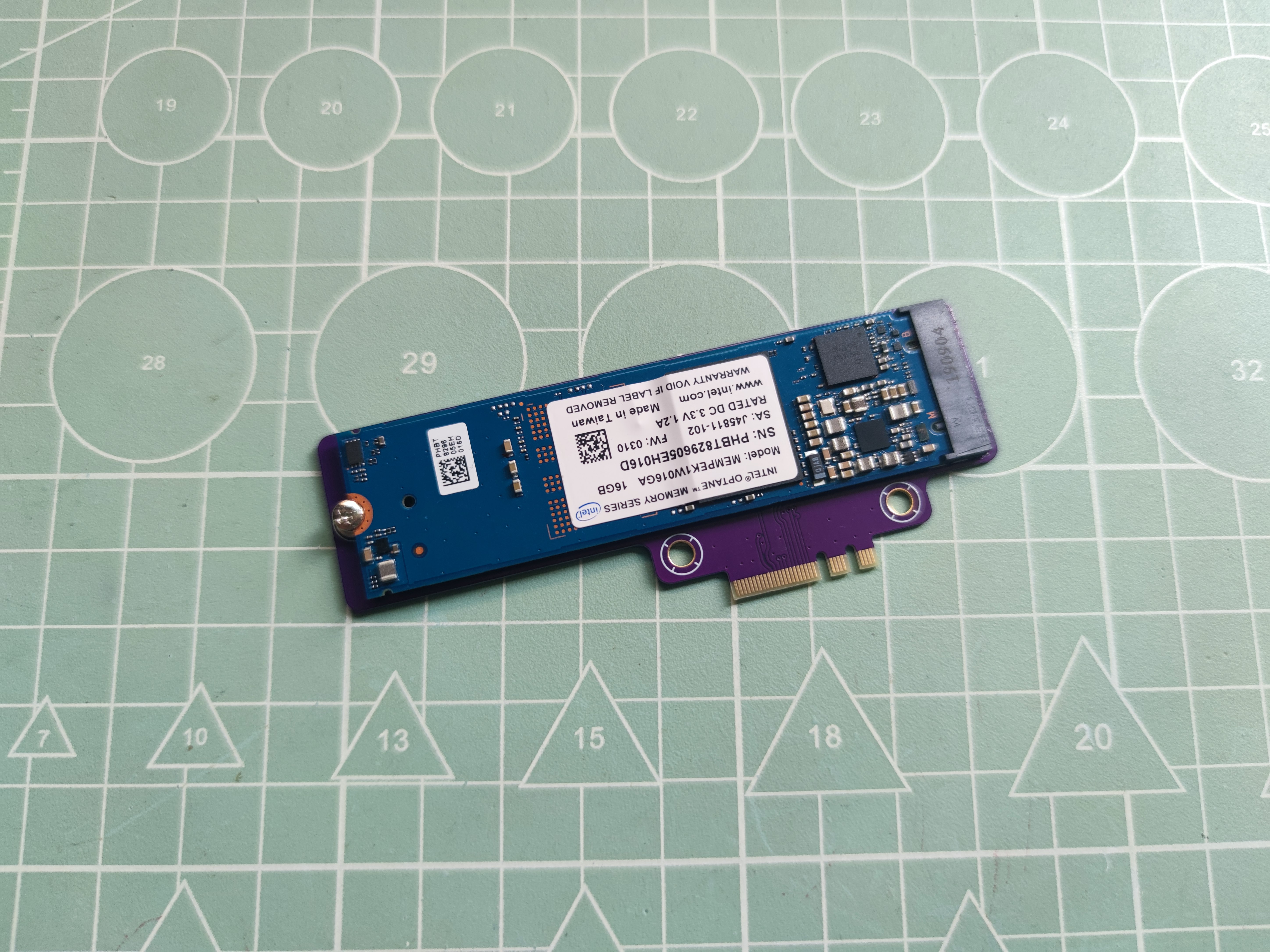
Figure 1: Front of the adapter module (with Optane 16G hard drive inserted)

Figure 2: Front of the adapter module

Figure 3: Back of the adapter module

Figure 4: Installation Image 1
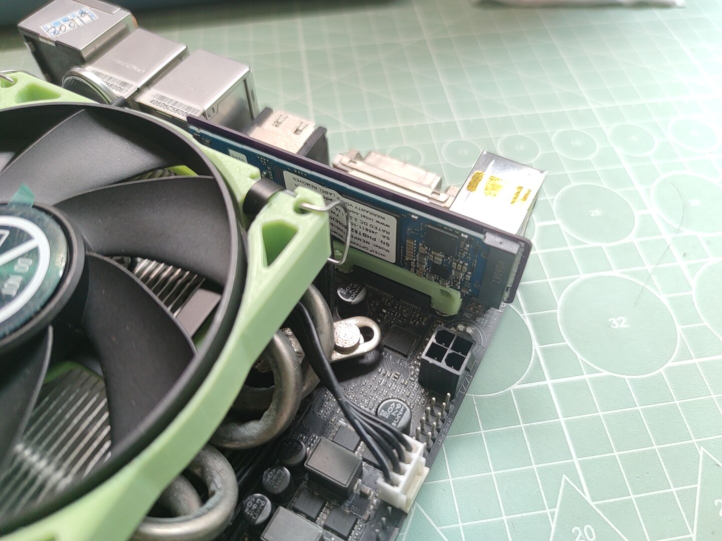
Figure 5: Installation Image 2
II. Functional Verification
Verification Platform:
CPU: QTJ2
Motherboard: GA-Z170N-WIFI REV1.0
Hard Drive: Intel Optane 16G
Verification images are shown below (correctly recognized in BIOS, subsequent verification shows entry into the PVE system):
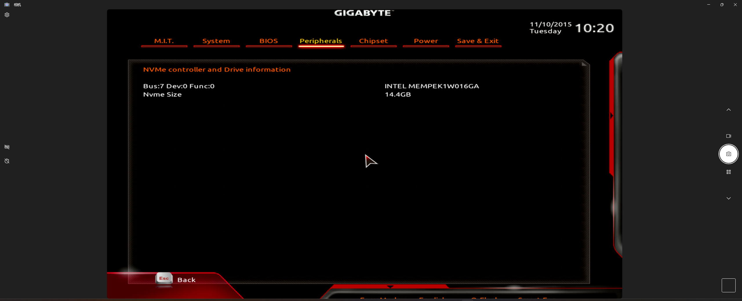
Figure 6: Verification Image
III. Replica Notes
Prototype Parameters: Board thickness 0.8mm, double-sided line spacing ≤6mil (differential impedance 100Ω),
speed PCI-E 3.0 x1 (depending on the motherboard, 4.0 impedance is also too high), not suitable for high-speed hard drives, Optane is okay for playing around with.
Please ensure there will be no interference on your motherboard before prototyping.
PDF_M.2 WIFI (A+E Key) to M.2 NVME Adapter Board.zip
Altium_M.2 WIFI (A+E Key) to M.2 NVME adapter board.zip
PADS_M.2 WIFI (A+E Key) to M.2 NVME Adapter Board.zip
BOM_M.2 WIFI (A+E Key) to M.2 NVME Adapter Board.xlsx
93211
electronic


 京公网安备 11010802033920号

 1KS010-85GT


