This expansion board integrates commonly used control modules, with all pins exposed. It includes a 0.96-inch IIC screen, a TB6612 motor driver, an MPU6050 gyroscope, an HC05 Bluetooth module, servo control I/O, laser head I/O, LED test points, and uses an ESP-32-S3 for wireless downloading. This is suitable for short-range debugging and downloading, allowing for downloading and debugging without needing to retrieve the chip. It can also be used as a general IoT chip.
All pins are consistent with LCSC's open-source porting documentation.
The first version of the Bluetooth module couldn't fit, as it was blocked by the motor driver; it has been moved slightly.
Wireless downloading tutorial: ESP32 DAP-Link | Yunsi Studio (yunsi.studio)
The software is below.
1. The three header pins of the wireless download port need to be connected to the SkyStar terminal using DuPont wires.

2. This wireless download test only supports packs of 2 or higher; a pack must be present for it to work.
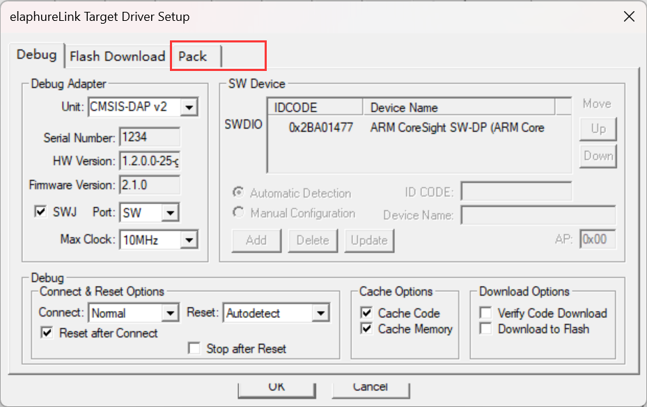

elaphureLink.zip
PDF_LCSC SkyStar Control Expansion Board.zip
Altium_LCSC Sky Star Control Expansion Board.zip
PADS_LCSC Sky Star Control Expansion Board.zip
BOM_LCSC SkyStar Control Expansion Board.xlsx
93224
#9th LCSC Electronics Design Contest# Desktop Temperature and Humidity Display
This is a DIY project submitted to the 9th LCSC Open Source Electronic Design Competition for "Sencerius Sensors," based on holocubic. Further code rewriting is being considered.
1. Project Function Introduction:
This project is a DIY entry for the 9th LCSC Open Source Electronic Design Competition by Sensiry Sensors, which creates a temperature and humidity detector.
The hardware part references the open-source project Holocubic:
1. The MPU650 was changed to a dial, which controls the switching between different apps;
2. An I2C interface and redundant I/O ports were added for expanding other applications;
3. A TP5400 was added for charge and discharge management;
The software part references Holocubic_AIO
: 1. The status action acquisition function was changed to implement dial control of the app;
2. An app program for displaying temperature and humidity data was added;
2. Project attributes:
first public disclosure;
original;
not involved in other projects ;
3. Open source license:
Public Domain;
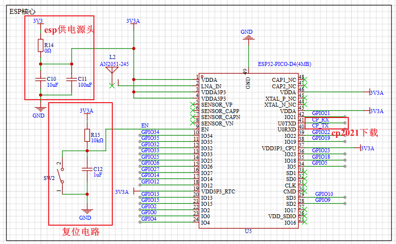
4. Hardware part : 1. ESP32 circuit diagram
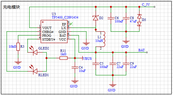
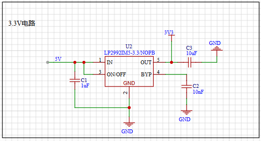
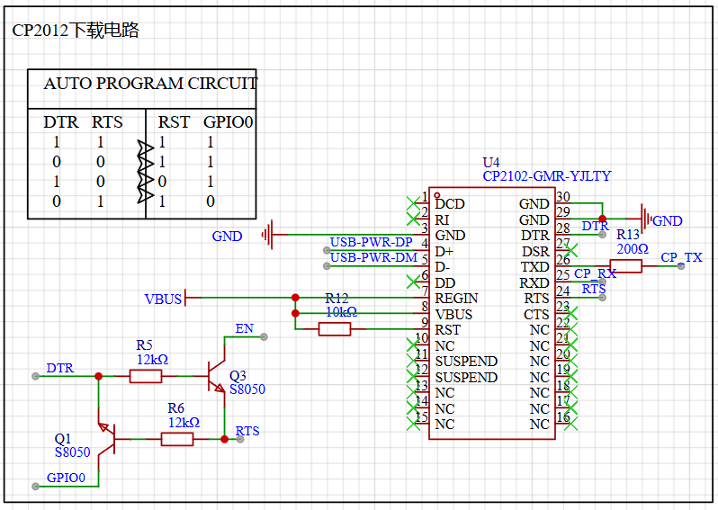
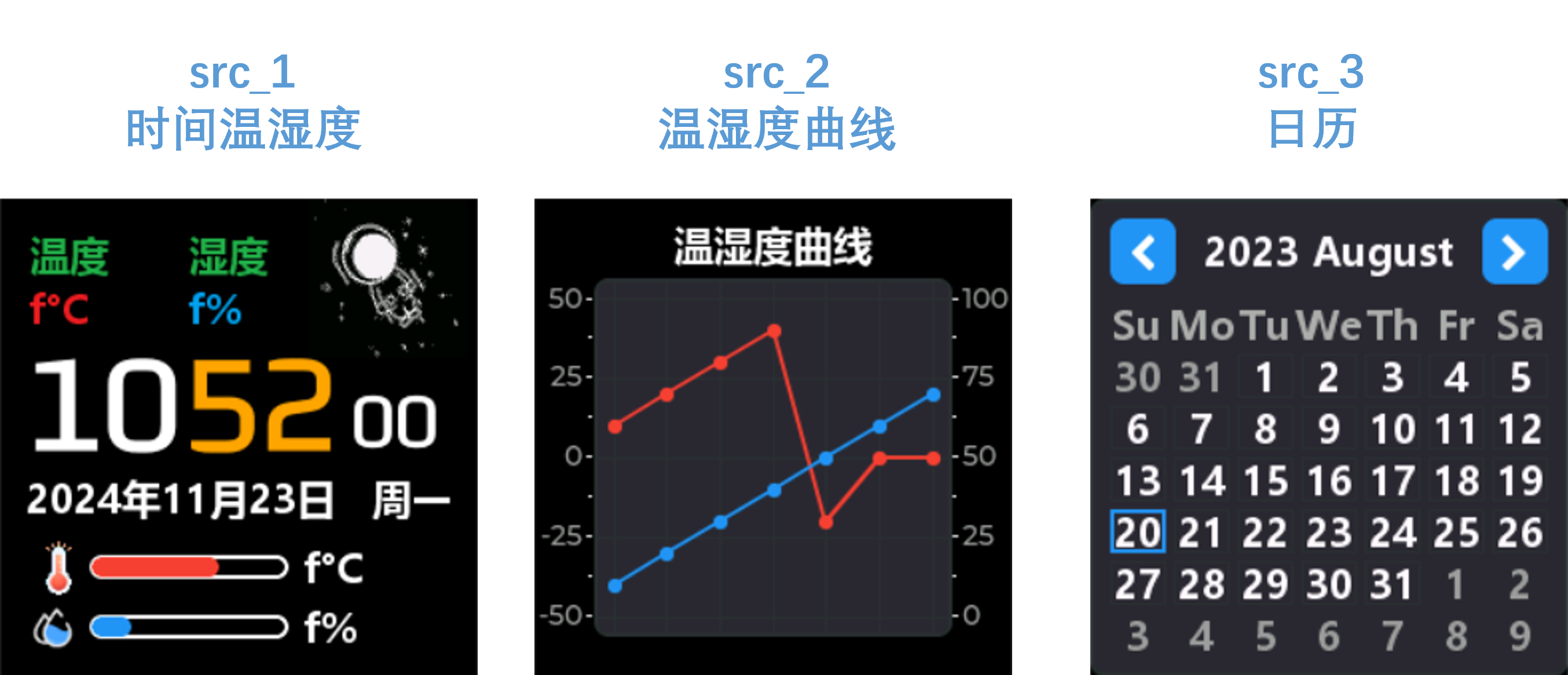
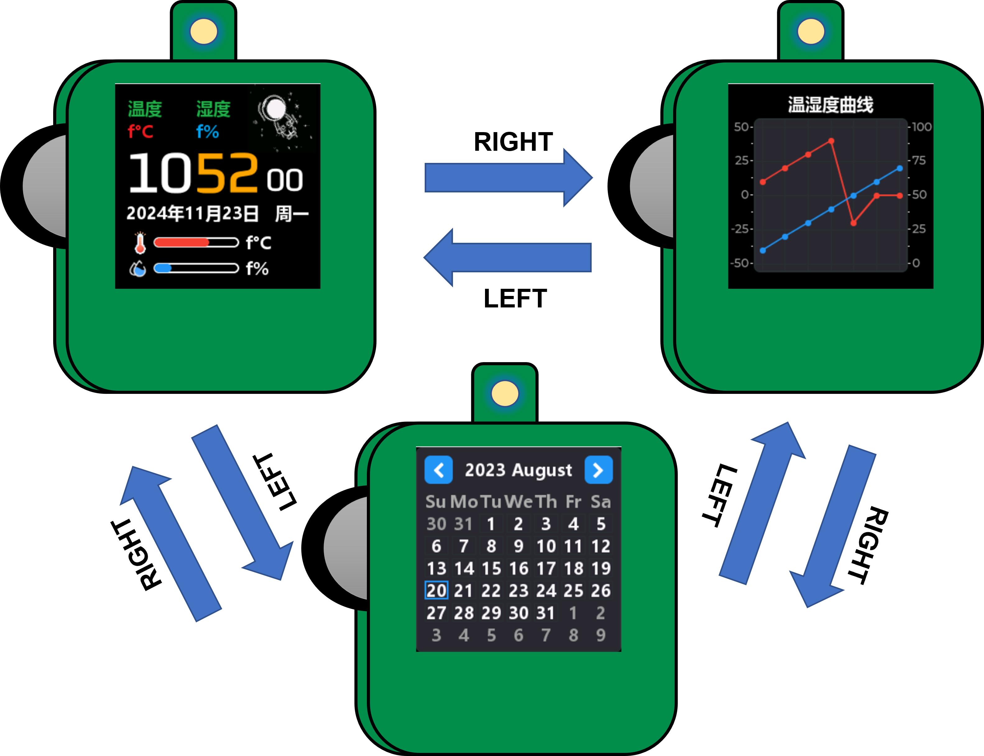
1. The minimum circuit of ESP32 mainly consists of three parts. The first is the power supply, which is provided by LP2992LP2992IM5-3.3/NOPB to ESP32 with a voltage of 3.3V. In the subsequent soldering or repair process, it can be detected through the 0Ω resistor R14; the second is the reset circuit, which mainly refers to the peripheral design schematic of the ESP32PICOD4 module. To ensure the normal power supply when the chip is powered on, EN An RC delay circuit needs to be added at the pin. The manual typically recommends R = 10 kΩ and C = 1 μF, but the specific values still need to be adjusted according to the power-on sequence of the module power supply and the power-on reset sequence of the chip. The third is the download circuit, which uses the CP2102-GMR-YJLTY to communicate with the host computer for download operations. The CP2102 automatic download circuit will be analyzed later. 2. Power Supply Section Figure 2-1 USB Power Supply Figure 2-2 Lithium Battery Charging and Discharging Figure 2-3 5V Power Supply Switching Figure 2-4 LDO Step-Down 3.3V Figure 2 Module Power Supply Circuit The power supply section of this project mainly uses USB and the lithium battery for input power. Figure 2-2 shows the lithium battery charging and discharging management circuit. The TP5400 chip has extremely low no-load power consumption (less than 10uA) and a boost output drive current capability of up to 1A. To manage the charging and discharging of the lithium battery, the charging current can be set by changing the resistance value of R3. The corresponding reference table is as follows: Table 1: Relationship between R3 and Charging Current R3 (Ω) IBAT 10k 130mA 5k 245mA 2k 560mA 1.5k 740mA 1.1k 1000mA Figure 2-3 shows a 5V power supply switching circuit. A USB and lithium battery power supply switching circuit is made using PMOS and rectifier diodes. If USB is connected, it directly powers the circuit; otherwise, the lithium battery powers the circuit. The 5V voltage can be controlled by switch SW1. Figure 2-4 shows an LDO step-down circuit, mainly for powering the ESP32 later. An LP2992 ultra-low dropout regulator is used to power the ESP. The PCB layout circuit is provided in the manual and can be referenced for PCB layout. 3. Download Circuit Diagram 3 CP2102 Automatic Download Circuit Download Mode: When the chip starts, if IO0 is low, the chip will enter download mode; Run Mode: When the chip starts, if IO0 is high, the chip will enter run mode; Set DTR = 1, RTS = 0, at this time Q1 is turned on, Q2 is turned off, EN = RTS = 0, IO0 = 1, the chip power-down resets; During the reset process, the ESP32 has an RC reset delay circuit, so EN has delayed buck and boost voltages. Set DTR = 0, RTS = 1, at this time Q1 is turned off, Q2 is turned on, EN = 1, IO0 = 0, the chip is powered on again, since IO0 is low, the chip enters download mode; Set DTR = 1, RTS = 1, at this time Q1 is turned on, Q2 is turned on, EN = 1, IO0 = 1. Ensure the chip is reset and running normally after downloading. 5. Software compilation environment: VsCode + PlatformIO. Code: climate-monitor. Figure 4 Interface display: src_1 - Displays time and temperature/humidity data, can perform network time synchronization, and displays SHT40 data acquisition. Network time synchronization is automatically calibrated every 15 minutes, and temperature/humidity data acquisition is once every 2 seconds. src_2 - Temperature and humidity data table display interface, collects temperature and humidity data every two seconds for display; src_3 - Calendar display . The state of the dial is adapted as shown in Table 2. Dial state corresponding to operation description. Dial state corresponding to operation value : RIGHT Up 0 LEFT Down 0 UP Up 1 DOWN Down 1 Change state value. Middle key 0, 1 to switch. CONFIRM Long up - BACK Long down || Long middle key - Switch the interface through the dial, network time synchronization, temperature and humidity detection, etc. Figure 5 Dial state switching description. 6. BOM list is at the end. 7. Competition LOGO verification. 8. Demo video is in the attachment. Go to view more details >


LCSC Electronics Contest: Temperature and Humidity Detector - Operating Instructions.mp4
PDF_#9th LCSC Electronics Design Contest# Desktop Temperature and Humidity Display.zip
Altium_#9th LCSC Electronics Design Contest# Desktop Temperature and Humidity Display.zip
PADS_#9th LCSC Electronics Design Contest# Desktop Temperature and Humidity Display.zip
BOM_#9th LCSC Electronics Design Contest# Desktop Temperature and Humidity Display.xlsx
93226
2024 Electronic Engineering Contest Problem G - Based on SkyStar STM32F401
This project originated from Problem G of the 2024 Electronic Design Contest. The aim was to improve my technical skills and teamwork through the contest, and to learn from the experiences of senior students to enhance my abilities.
I. Team Introduction: Team members
from the Applied Electronic Technology program at Wuhan Transportation Vocational College (Qin Yunfa, Li Xian, Yang Jiale) participate.
II. Project Requirements
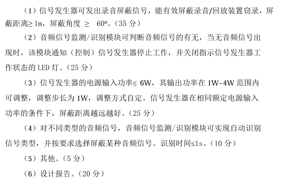
III. Design Summary
: Complete ultrasonic shielding that effectively blocks input sound signals.
IV. Project Analysis:
1. Complete basic ultrasonic shielding.
2. Building upon ultrasonic shielding, complete the following (increasing the propagation distance and angle by 1m is full marks) (achieve sound detection and silence by pausing the speaker's voice).
3. Adjust the power step to 1W (with the input power to the shield less than 6W and the output power 1-4W)
. The
following is a description of the ultrasonic shielding device, which requires sound type identification and shielding selection .
The principle is based on the high-frequency signal of ultrasound causing the phone's microphone to vibrate. When other sounds arrive, their low frequency is insufficient to change the microphone's vibration amplitude (the change is minimal), resulting in continuous microphone vibration and a loud, noisy sound. An
operational amplifier drives the ultrasonic transmitter, similar to a speaker, but requiring sound type identification and shielding selection. Fourier transform can be used, but technical limitations exist. This is an open-source project hoping for improvement from users. The
hardware circuit components
are as follows:
1. Multiple ultrasonic transmitters (T-type) connected in parallel (the more, the better).
2. Skystar STM32F401 development board (youth version), other 401 boards can also be used, but LCSC's is truly excellent
. 3. Sound detection module, LM358, LM393.
4. Single-channel 5W power amplifier chip LTK5128. This chip has an enable pin that can be directly driven to turn off by high and low levels with low latency. Note: If high and low levels are used to control the relay, the latency will be very high, 1-2 seconds.
(Other power amplifiers or H-bridges (LM298N motor drivers can also be used), half-bridges, and full-bridges can also be used.)
5. Multiple DuPont wires, header pins, header nuts, LEDs, 1k and 2k base resistors, etc.
VII. The program
first acquires ambient white noise (voltage value), then uses an ADC to collect the sound sensor signal, and then outputs high and low levels to control the LED to indicate the on/off state of the shield. The principle is that the LED is pulled up by a resistor, and a low level turns it on, and a high level turns it off, driving the enable pin of the LTK5128 to control the on/off state. VIII. See the attached document for
a physical demonstration . IX. Precautions: This is an improved version of the PCB, but two buttons have not been tested. Please use with caution. X. See the attached document for a demonstration video . XI. Attachment Contents: Attachment 1: Sound LED On/Off Demonstration; Attachment 2: Real-time Recording of Ultrasonic Shielding; Attachment 3: Test Room Title (Approximate); Attachment 4: Physical Demonstration; Attachment 5: Source Code
Ultrasonic LED continuity test.mp4
Ultrasonic Shielding Test Recording.m4a
Testing Room (approximately).jpg
source code.zip
Board style.jpg
PDF_2024 Electronic Engineering Contest Problem G - Based on SkyStar STM32F401.zip
Altium_2024 Electronic Engineering Contest Problem G - Based on SkyStar STM32F401.zip
PADS_2024 Electronic Design Contest Problem G - Based on SkyStar STM32F401.zip
BOM_2024 Electronic Design Contest Problem G - Based on SkyStar STM32F401.xlsx
93227
electronic


 京公网安备 11010802033920号

 HLMP-S30X


