The CT7601 decoding chip + PCM5102A DAC + CS5340 ADC + LPA4722 headphone amplifier + SGM2549D headphone switching IC provide
150mW drive power.
It supports both CTIA and OMTP standard headphones.
My ears only detected a very loud sound; more key parameters haven't been tested with professional equipment yet. I'll test them when I have time.
The CT7601 requires firmware flashing; the flashing method and software are in the attached compressed file.
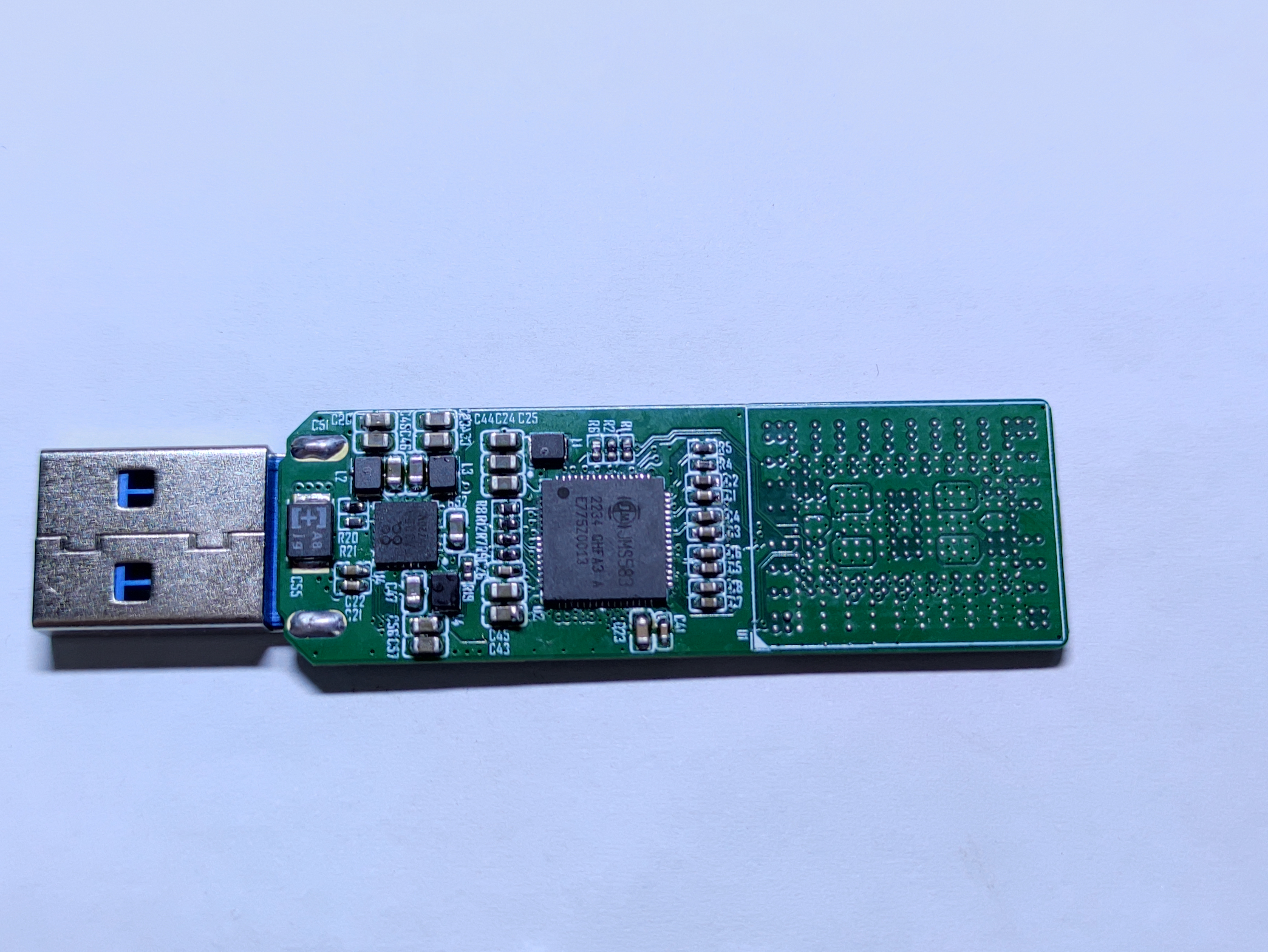
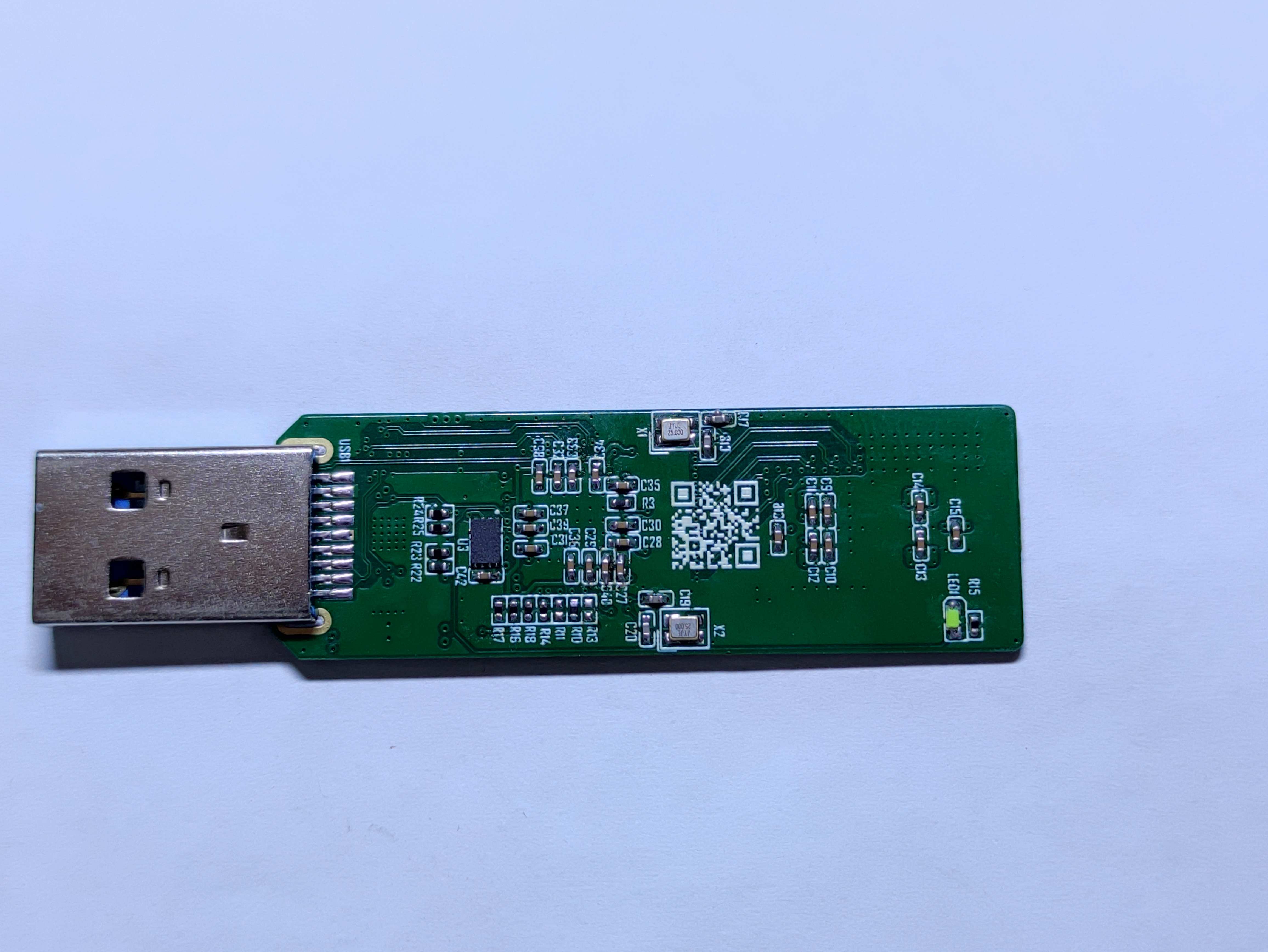
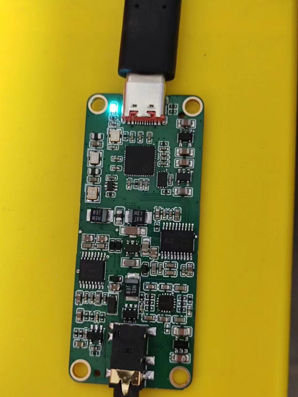
The controller is a JMS583 bridge chip, with USB 10G-PCIE3.0 x2 ports. Paired with BGA291 SSD NAND flash memory, its performance surpasses many USB flash drive solutions.
It is compatible with most NAND flash memory chips with 3.3V, 1.8V, and 1.2V three-way power supply, such as Kioxia BG3 and BG4, Samsung PM971, PM991, and Hynix BC501.
Note that Samsung PM971 and PM991 require an additional X1 crystal oscillator; PM971 works fine in testing, PM991 is untested
and incompatible with the most powerful BC711, which requires four power supplies with completely different voltages.
The firmware flashing tool is attached; it allows modification of names and power-saving settings.
Both the NAND flash memory and controller generate significant heat, requiring an aluminum casing with thermal pads. Testing showed that a 2mm pad on one side and a 1mm pad on the other side is just right for pressing
the casing firmly.

JMS583.zip
PDF_BGA291 High-Speed USB Flash Drive.zip
Altium_BGA291 high-speed USB flash drive.zip
PADS_BGA291 High-Speed USB Flash Drive.zip
BOM_BGA291 High-Speed USB Flash Drive.xlsx
93341
PEX8748 PCIe Expansion Card
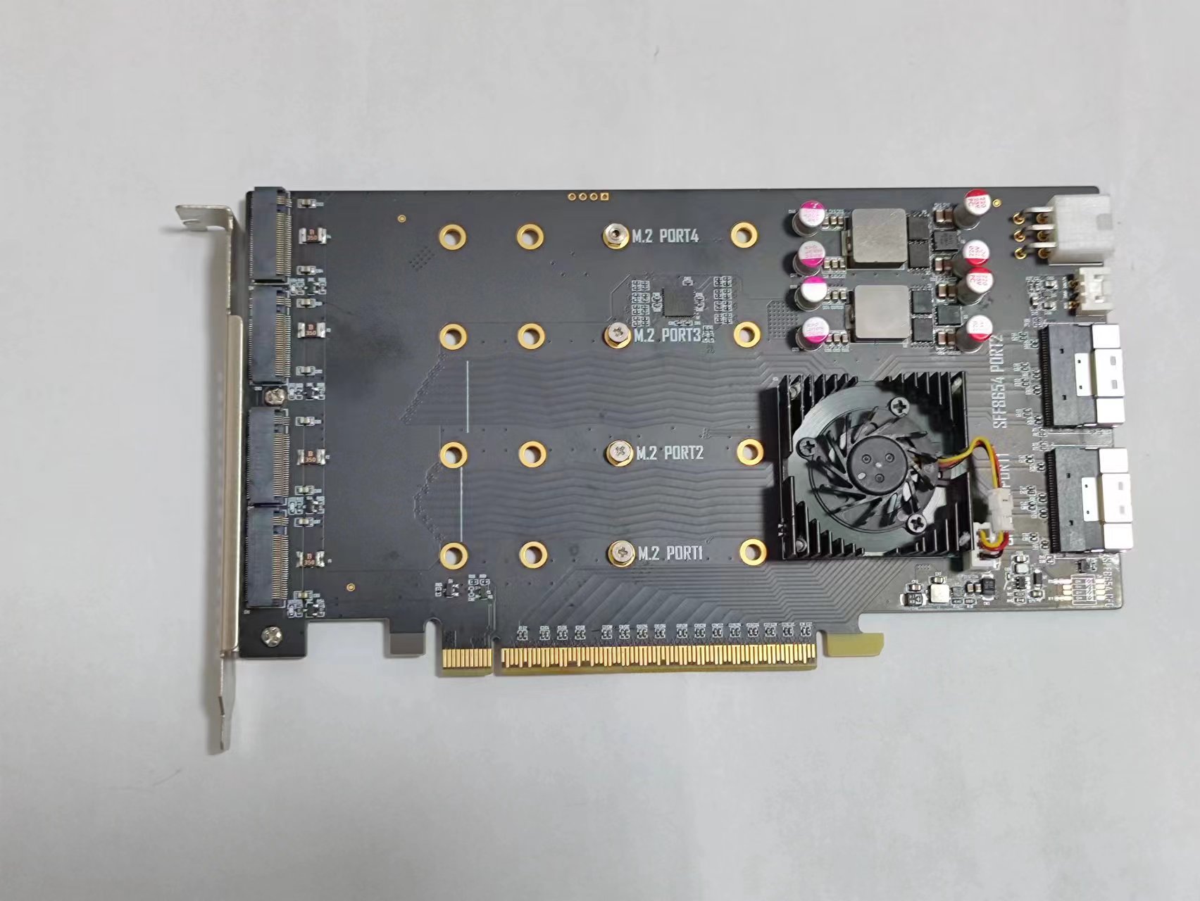
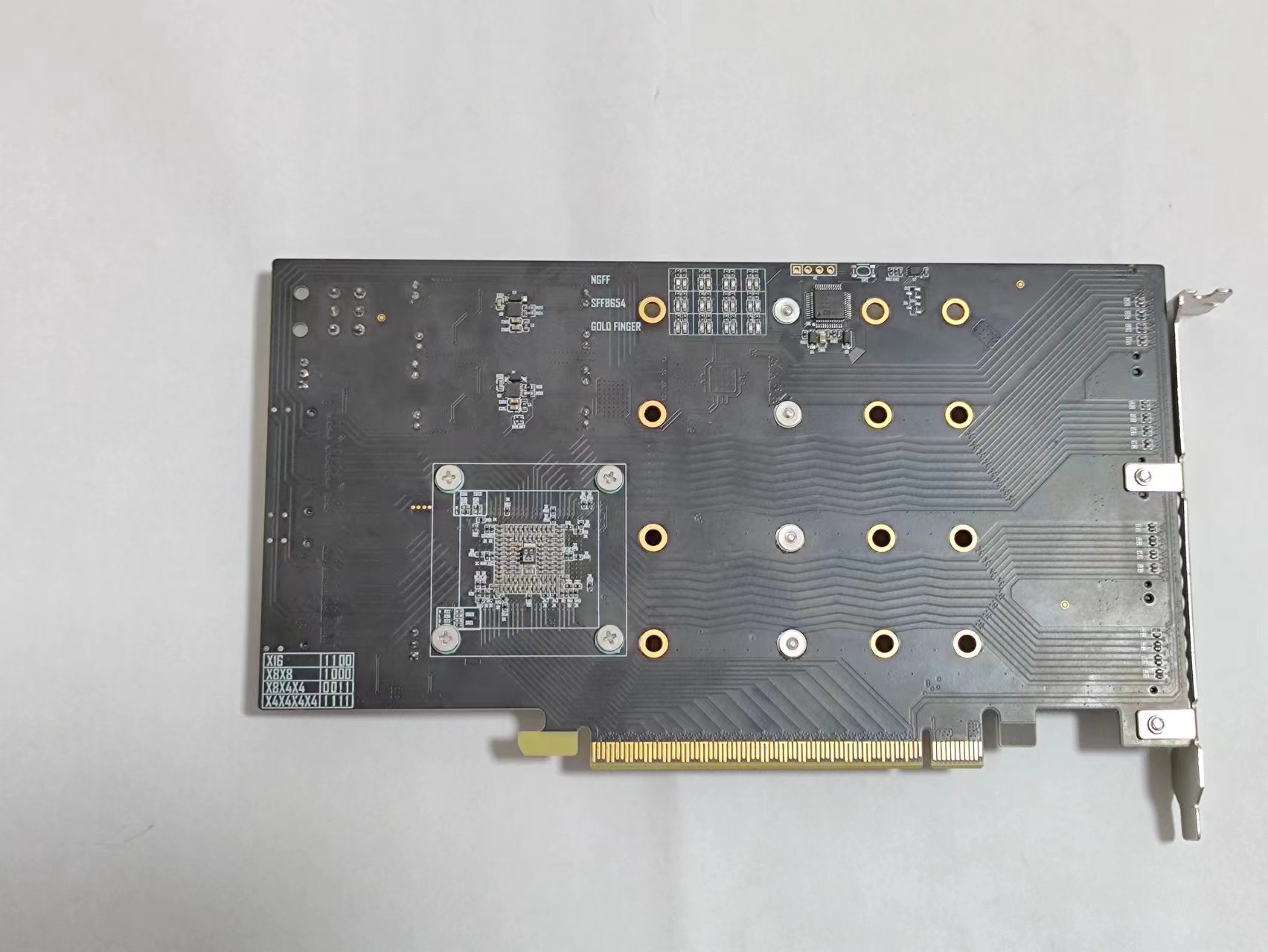
This PCIe expansion card, based on the PEX8748 PCIe switch, incorporates an MCU to resolve the issue where the PEX card, when used with certain SSDs, could only negotiate PCIe Gen1, and can also display the working status in real time.
This PCIe expansion card, based on the PEX8748 PCIe switch, expands from a single PCIe x16 slot to provide four M.2 interfaces and two SFF-8654 8i interfaces
. Modified from this project, some changes have been made
, including a shorter overall layout and
the addition of an MCU to address the issue of some SSDs only negotiating PCIe Gen1 when used with the PEX8748
. The MCU can read the status, connection speed, and width of each interface, displaying this information in real-time via LEDs (see video).
Impedance stacking is explained in the PCB file.
The attached bin file contains the MCU's program; STM32 cube programmer is recommended. I/O
shield and
heatsink connections are also provided.
x264.mp4
pex8748.bin
PDF_PEX8748 PCIE Expansion Card.zip
Altium_PEX8748 PCIe Expansion Card.zip
PADS_PEX8748 PCIe Expansion Card.zip
BOM_PEX8748 PCIe Expansion Card.xlsx
93342
STC8G1K08A_board
STC8G1K08A ultra-small system board, supports USB download.
STC8G1K08A Ultra-Small System Board
Note:
Except for P3.0 and P3.1, all other I/O ports are in a high-impedance input state after power-on. Users
must configure the I/O port mode before using it.
All I/O ports can be set to quasi-bidirectional port mode, strong push-pull output mode, open-drain output mode
, or high-impedance input mode. Additionally, each I/O port can independently enable its internal 4K pull-up resistor
. When P5.4 is enabled as the reset pin, the reset level is low.
For the STC8G1K08 series B version chip, P5.4 is used as an I/O port. When using the port, the current should not exceed 50mA,
and strong impacts should be avoided.
The USB download supported by the STC8G1K08 series B version chip is a software-simulated USB connection via the I/O port. Due to factors such as manufacturing process and temperature, a certain percentage of chips may fail to perform USB downloads. Actual testing shows that the failure rate is approximately 5% to 8%.
Four chips (V1.0) were soldered: one 08 chip, two 08A chips, and one 17 chip. The 17 chip failed to perform USB downloads.
Version 2.0: Optimized silkscreen and layout.
PDF_STC8G1K08A Minimum Board.zip
Altium_STC8G1K08A Minimum Board.zip
PADS_STC8G1K08A Minimum Board.zip
BOM_STC8G1K08A Minimum Board.xlsx
93344
electronic


 京公网安备 11010802033920号

 CFPO-DO-451BS12A8.0N


