 The purchased screen cable may be 24-pin or 26-pin. If it is the former, please purchase a 24-pin FPC socket for soldering; if it is the latter, you need to apply transparent tape to the back and cut the cable to a narrower width to insert it into the 26-pin FPC socket without it falling out.
 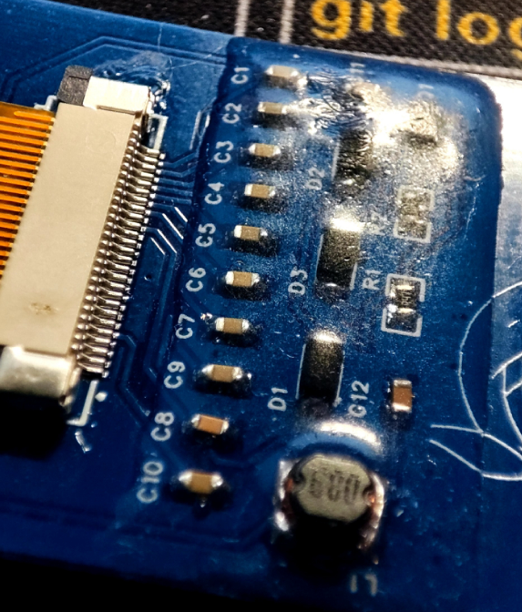 Image Preview

 Since all components are powered by 3.3V, and the power supply is two 3.7V 14500 batteries, the 7.4V power supply needs to be stepped down. The LM1117S is selected for step-down, and the power supply and step-down module circuit is as follows.
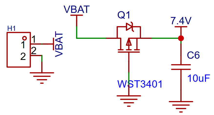
 Considering that the chip needs to achieve low-power operation, the RTC needs to be enabled to ensure time accuracy; therefore, an external crystal oscillator is used, and its circuit is as follows
  . Simultaneously, a wake-up button is needed to switch the chip from stop mode to run mode.
  The SHT40 temperature and humidity sensor module circuit uses IIC communication with the MCU, where the SDA and SCL lines need to be connected to pull-up resistors.
  To achieve program download, the SWD download and debugging interface circuit is as follows
  . A user-defined button is provided, which I define here as page scrolling up and down, and confirm and cancel.
 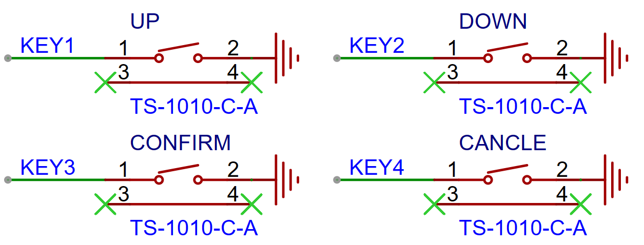 To store temperature and humidity data and character data, an EEPROM is required. Note that the EEPROM communicates with the MCU via IIC, therefore pull-up resistors are needed for the SDA and SCL lines.
  A 1.8-inch TFT screen is used for the LCD, which communicates with the MCU via SPI. The circuit is as
  follows: To allow the LCD to turn off in MCU stop mode, I added a latching switch between the power supply and the LCD's VCC pin. However, this was found to be unnecessary, as the screen can be turned on/off by changing the level of the backlight pin (BL). Therefore, the latching switch can be removed. During subsequent debugging, it was found that the LCD screen can still light up without VCC power, but the brightness is dim. Therefore, if the application scenario is at night and the screen brightness is a concern, the latching switch can be retained.
  To enable communication with the mobile app, a Bluetooth module is added. The Bluetooth module used is a 6328A serial Bluetooth module, part number C20539408. Since there was no model in the EDA for this Bluetooth module, I used a 1x5pin header instead. Also, because the Bluetooth module uses a stamp-hole connection, the model in the EDA could be changed to a surface mount design, thus reducing the height of the Bluetooth module and allowing more height for the LCD screen, thereby reducing the overall thickness of the temperature and humidity sensor.
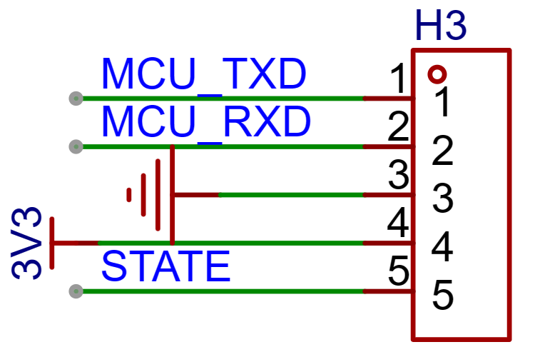
 Finally, to test and monitor the MCU's operating status, an LED was added.
  During the PCB design, to reduce electromagnetic interference and the impact of the manufacturing process, the copper plating at the bottom of the crystal oscillator and any sharp-shaped copper areas needed to be removed by setting forbidden areas
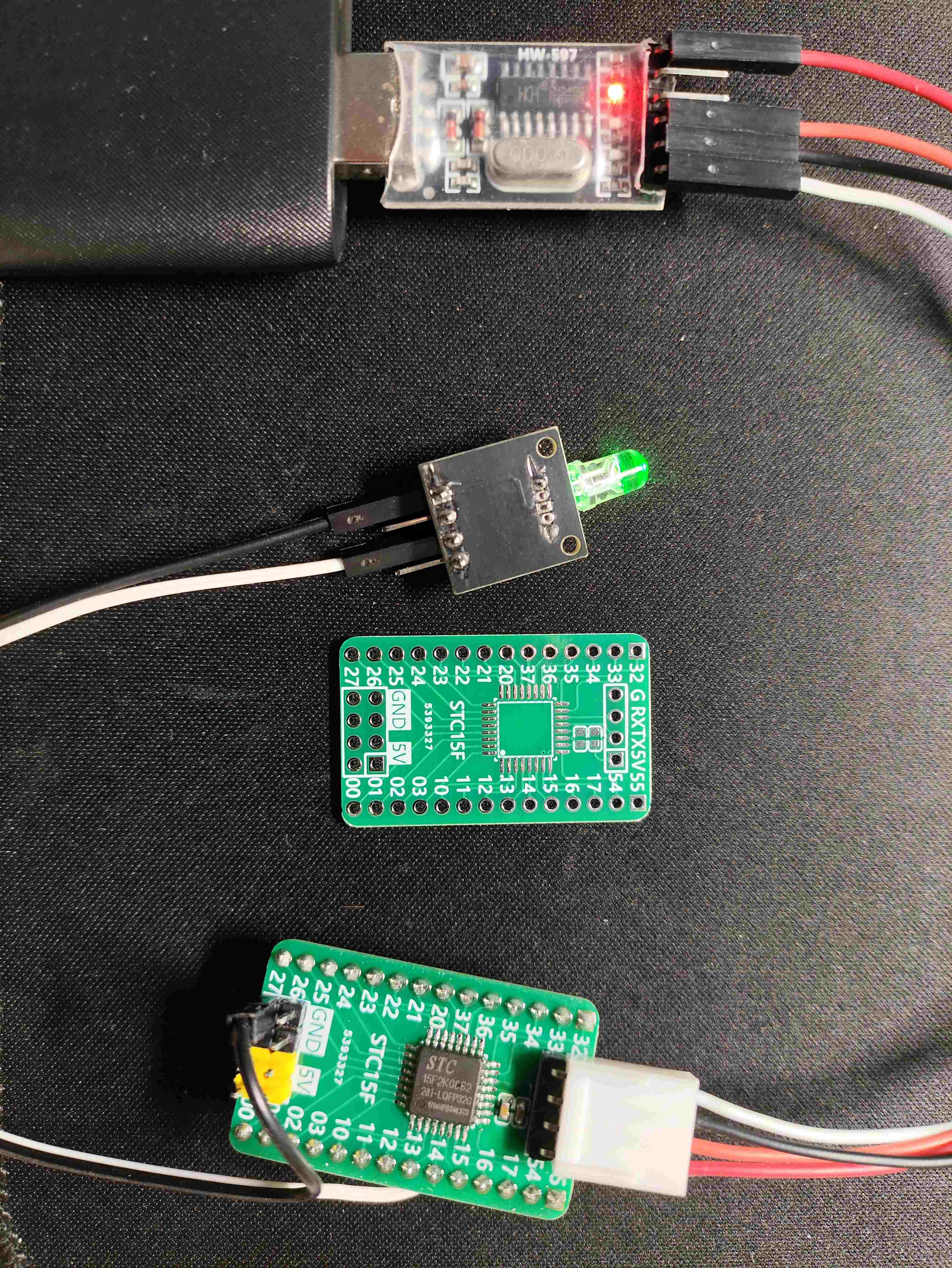
 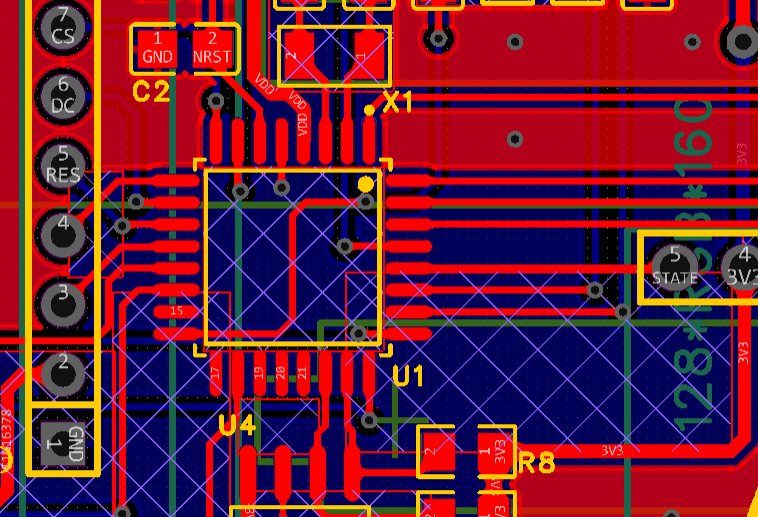 . The final circuit board and related components are shown in Figure
 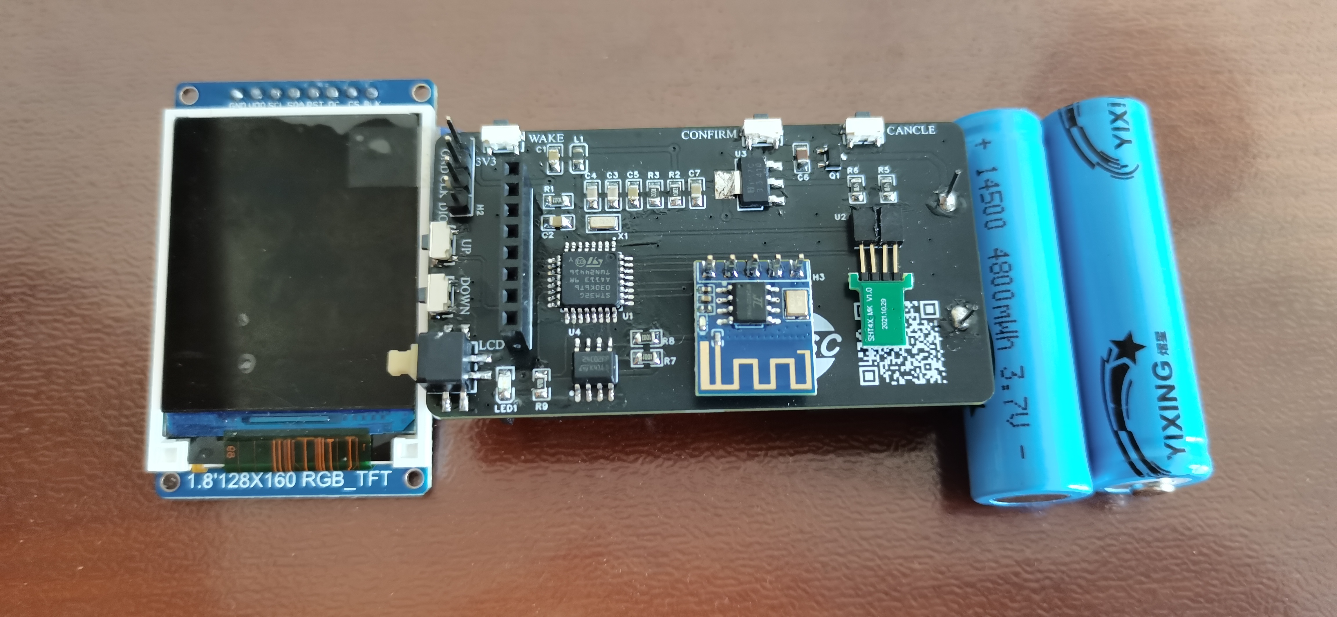 3. The software design
  . To ensure the RTC operates normally, the RCC needs to be configured first, and the LSE set to an external crystal oscillator
  . Next, the RTC needs to be configured, including the time representation method (binary/BCD) and the initial time.
 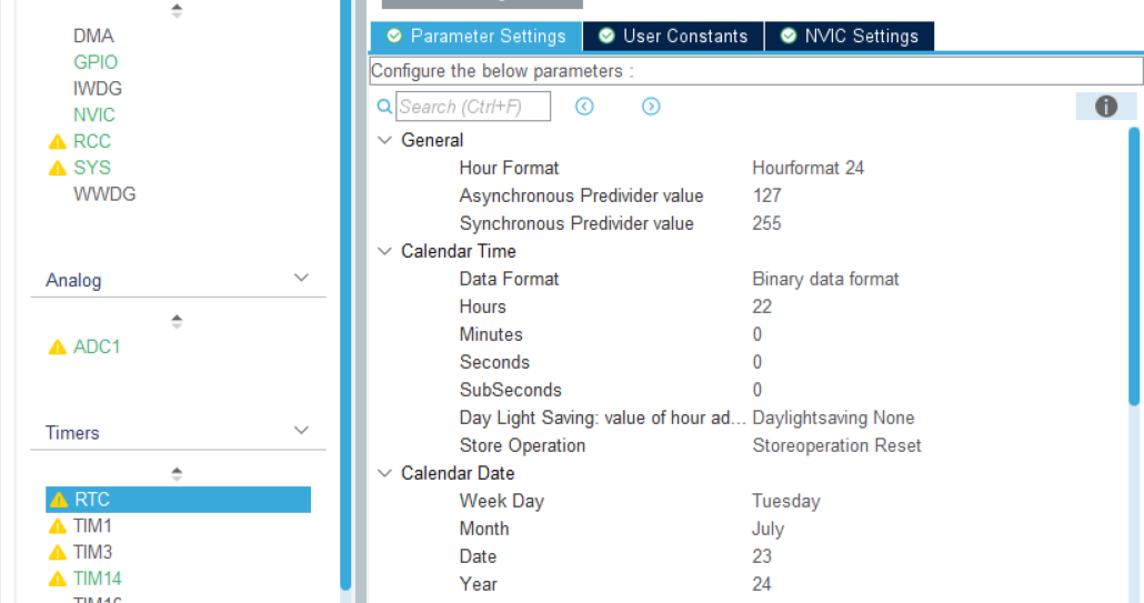 Other methods such as I2C, SPI, and USART can be implemented by referring to various tutorials.
  . The date and time modification interface implements functions such as time modification and cursor blinking. The rules are: the last two digits of the year, month, date, hour, and minute can be changed. Pressing the UP/DOWN button without any operation will switch to page 0. The first press of the CONFIRM button locks the YEAR value; pressing the UP/DOWN button again will change the YEAR value. Pressing the CONFIRM button again will move the cursor to the next value. Press the CANCEL button to adjust the end date and time.
  To further reduce MCU power consumption (the MCU current is in the mA range in sleep mode, while it is only in the uA range in stop mode), the MCU will enter stop mode after the detector has been inactive for 10 seconds. To exit stop mode, the MCU can be woken up by pressing the wake-up button. It is important to note that when the MCU enters stop mode, the chip's HSI clock will stop and switch to the LSE clock. Therefore, in addition to waking up the MCU, the RCC needs to be reconfigured to prevent timing errors in the tick timer.
  Since Bluetooth is a serial Bluetooth, only the printf function needs to be redefined.
 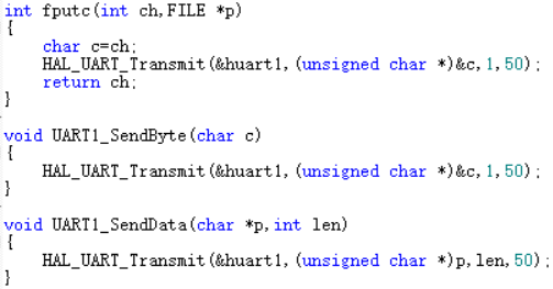 In addition, it is important to note that when using printf, please check "Use MicroLIB" in the magic wand; otherwise, printf will not work.
  Bluetooth APP design uses MIT App Inventor, which is an APP design webpage with the URL http://app.gzjkw.net/.
 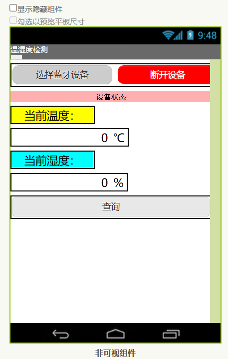 and write the APP backend code.
  4. Physical demonstration
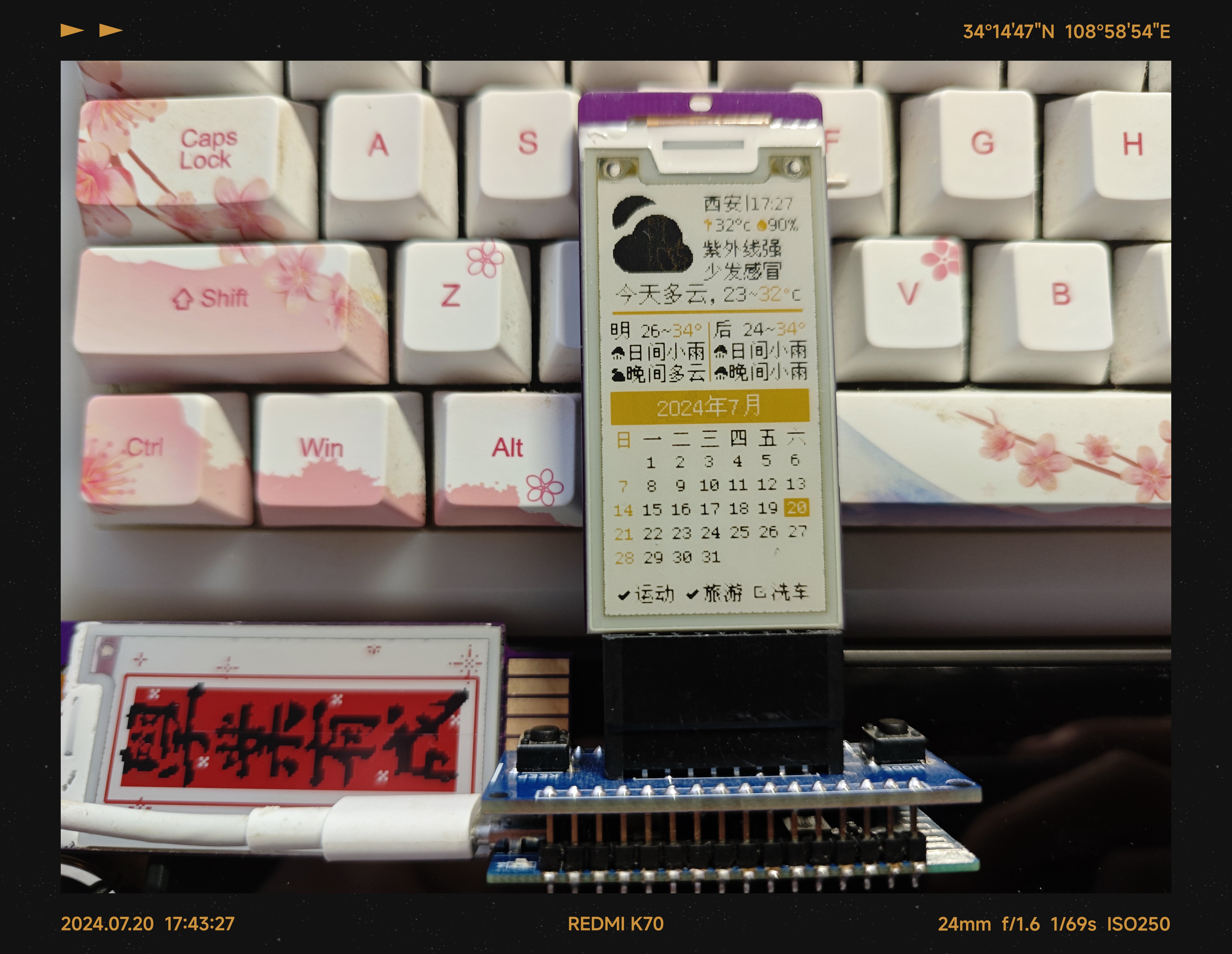
  Press the left up and down keys to enter the date and time setting interface. Press the OK/Cancel key in the upper right corner and the left up and down keys to increase or decrease the time.
 After setting, press the left up and down keys to switch to the temperature and humidity detection interface. You can see that the time has been successfully set.
 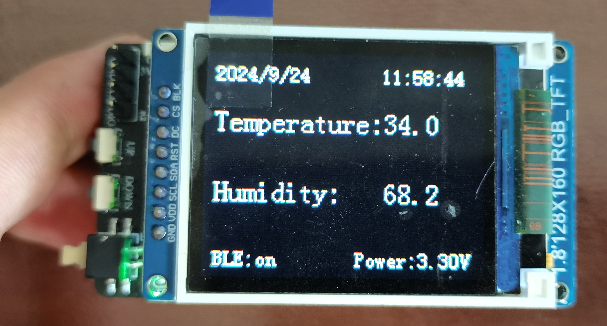 Open the mobile Bluetooth APP
  and select the Bluetooth device.
 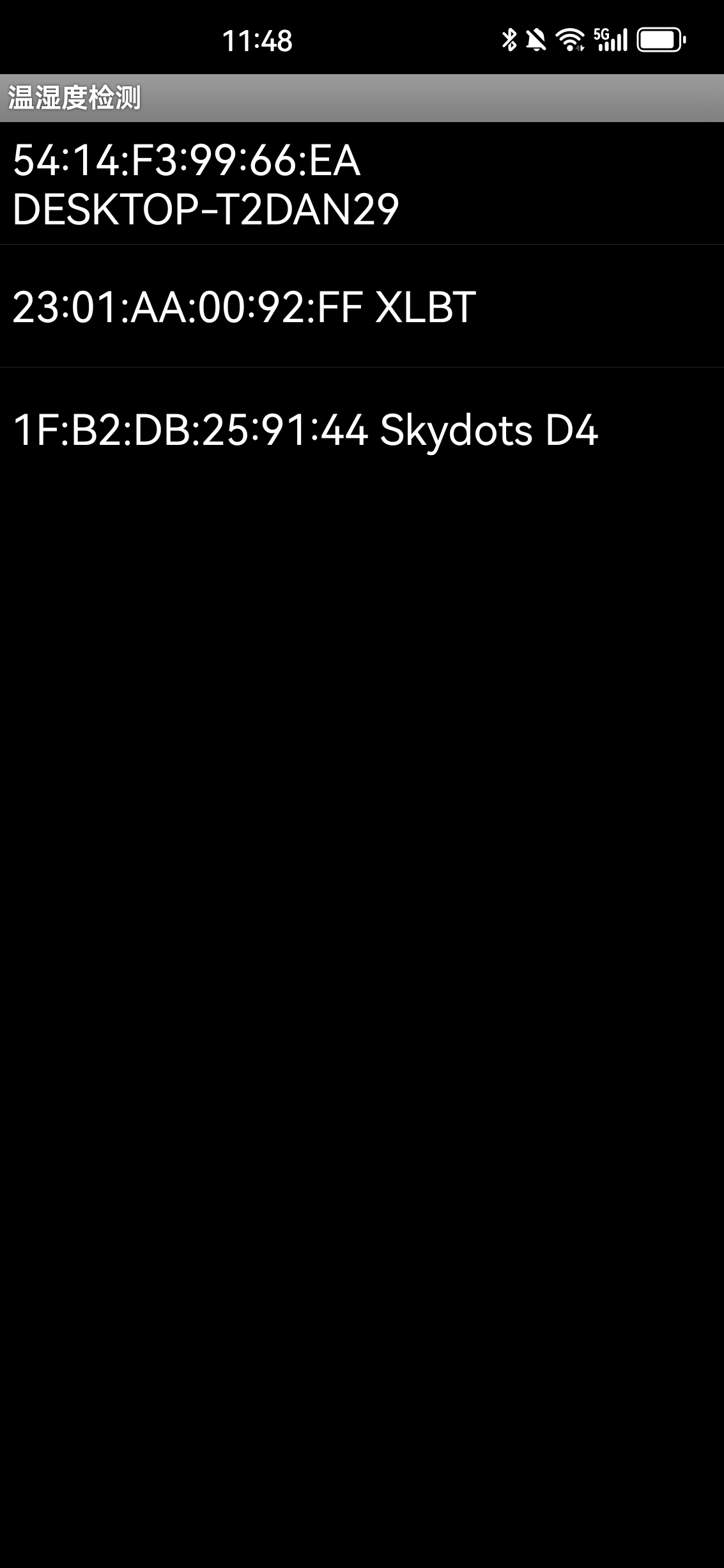 When Bluetooth is successfully connected, the Bluetooth module's connection indicator light will light up, and the data display interface will also show that Bluetooth is connected.
  Click the query button to query the current temperature and humidity.
 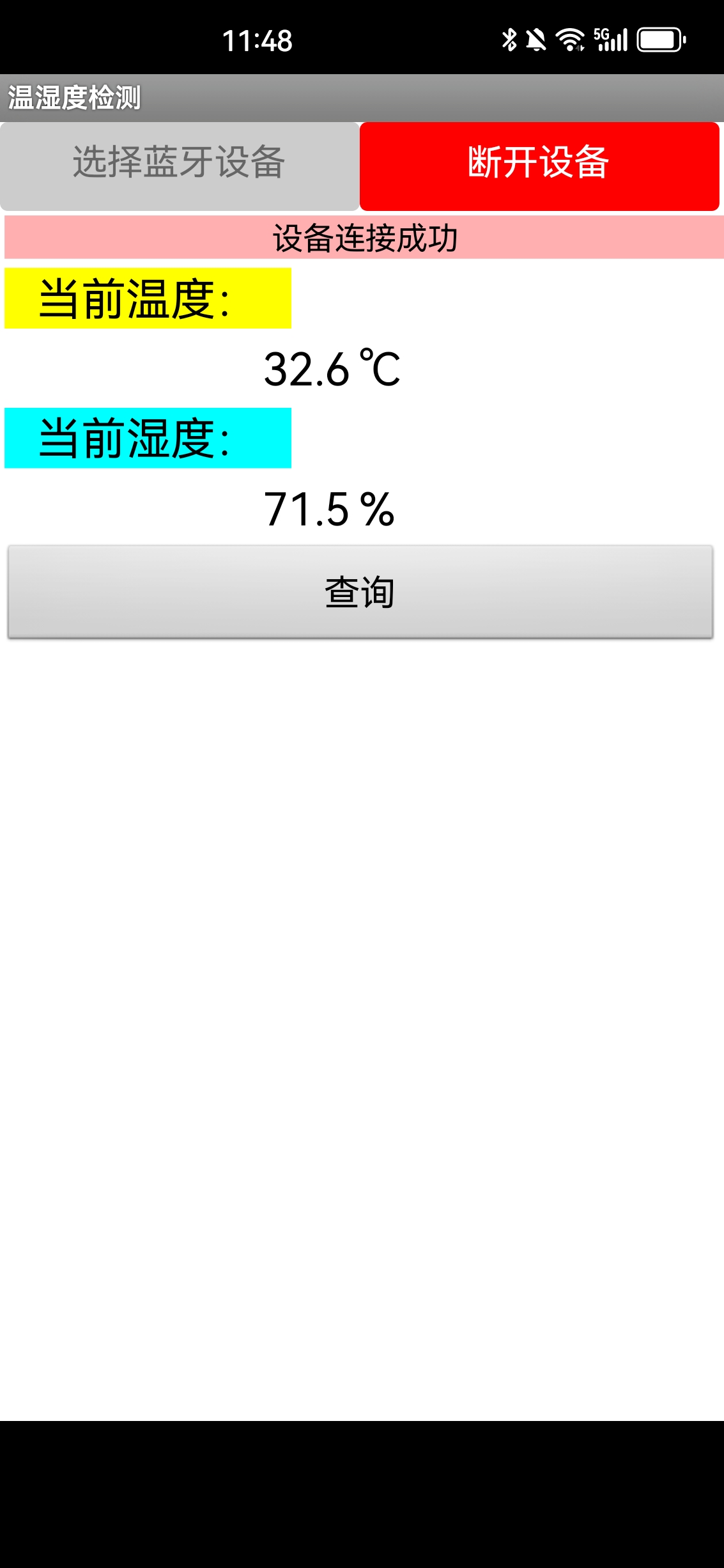 5. Attachment Descriptions
All reference designs on this site are sourced from major semiconductor manufacturers or collected online for learning and research. The copyright belongs to the semiconductor manufacturer or the original author. If you believe that the reference design of this site infringes upon your relevant rights and interests, please send us a rights notice. As a neutral platform service provider, we will take measures to delete the relevant content in accordance with relevant laws after receiving the relevant notice from the rights holder. Please send relevant notifications to email: bbs_service@eeworld.com.cn.
It is your responsibility to test the circuit yourself and determine its suitability for you. EEWorld will not be liable for direct, indirect, special, incidental, consequential or punitive damages arising from any cause or anything connected to any reference design used.
Supported by EEWorld Datasheet
EEWorld
subscription
account

EEWorld
service
account

Automotive
development
community

Robot
development
community

About Us Customer Service Contact Information Datasheet Sitemap LatestNews


Room 1530, 15th Floor, Building B,
No.18 Zhongguancun Street,
Haidian District,
Beijing, Postal Code: 100190
China
Telephone: 008610 8235 0740
 京公网安备 11010802033920号

 MI-P703-MYZ


