I. Development Board Function Overview
1. Direct USB download and simulation
2. Full-color REG circuit
3. Passive buzzer
4. Two-digit LED display 5.
DS118B20 temperature sensor, DHT11 temperature and humidity sensor
6. Infrared receiver
7. 485 communication 8.
555 counter
9. ADC voltage measurement
10. Photoresistor voltage measurement
11. RTC clock
12. LED circuit
13. Button circuit
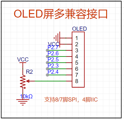
14. OLED screen interface compatible with SPI-7pin, SPI-8pin, and IIC-4pin
15. Three-pin universal sensor interface
16. Four-pin sensor interface for PCF8563/BMP180/MPU6050, etc.
17. Power interface (power voltage header leads)
18. All pins of the STC8051U chip are brought out.

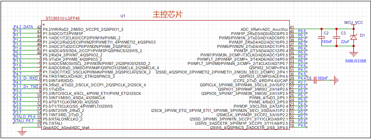
II. Schematic Introduction:
The main control chip
is based on the STC8051U. The datasheet details that
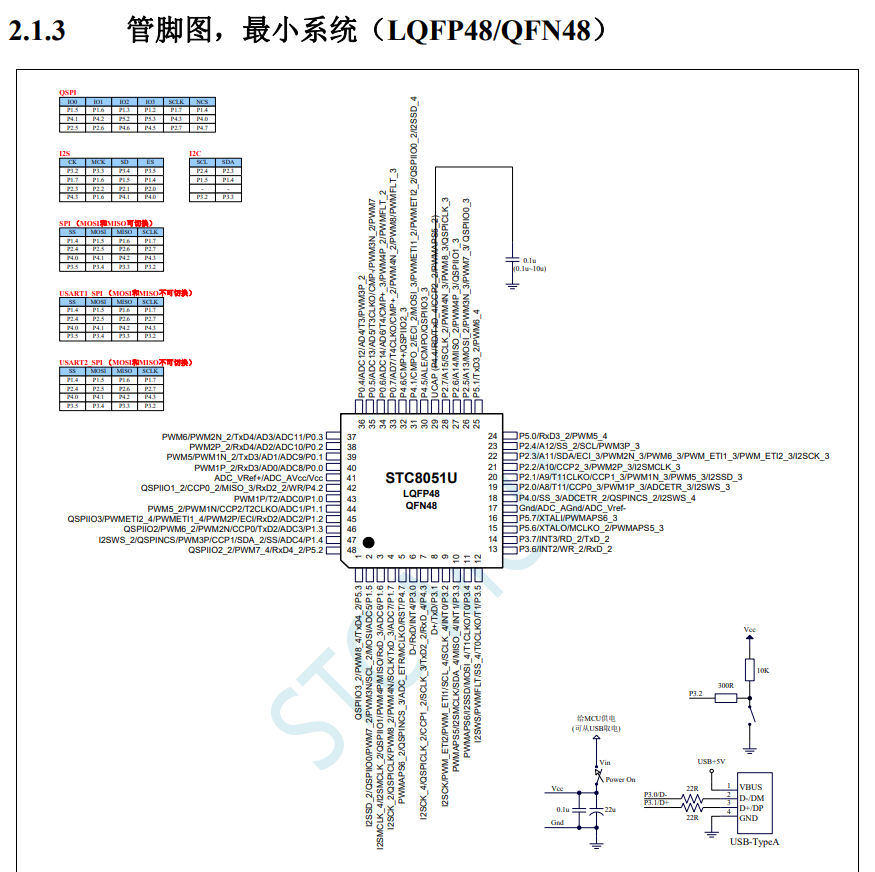
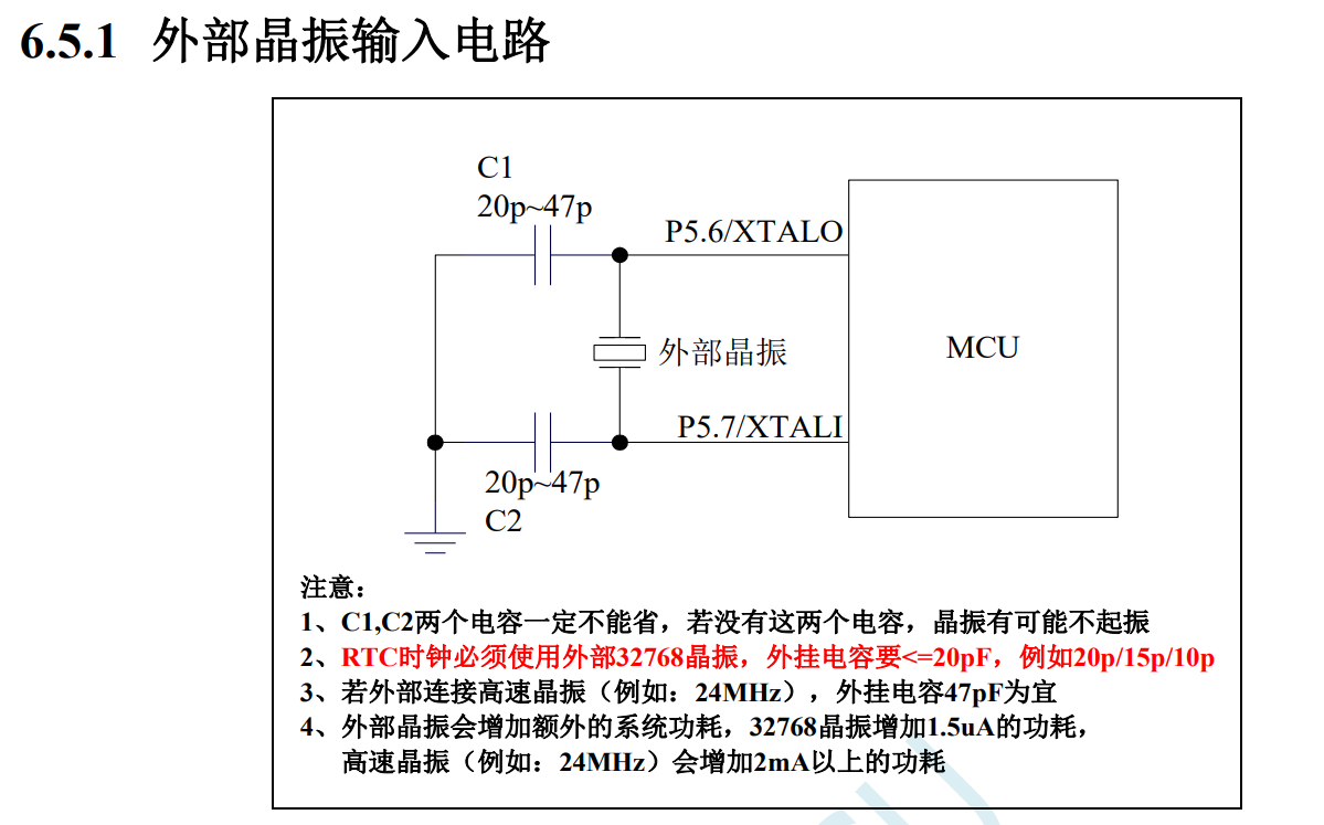
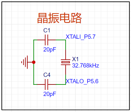
the RTC clock
must use a 32.768kHz clock. This is because dividing the 32.768kHz clock frequency 15 times yields a frequency of 1Hz.
One second is exactly 1Hz, which facilitates the generation of a 1-second clock frequency.
The button circuit
does not require pull-up resistors and capacitors, which is very convenient. The P32 port button can be used for downloading via


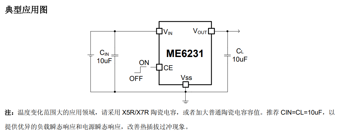
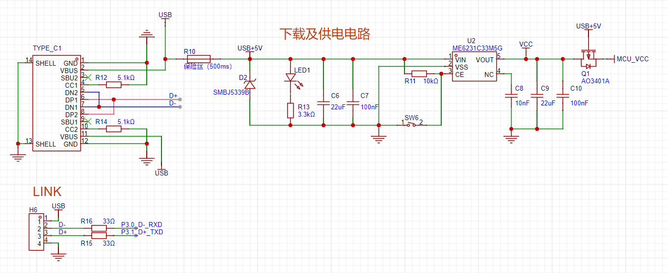
TYPE-C. The power supply circuit
is based on a ME6231 high-precision low-dropout linear regulator. The CE pin of the regulator chip is connected to the switch,
used in conjunction with the P32 button for power-on/off operations during downloading, thus enabling the use of the USB-HID communication protocol.
The external header is used to connect tools such as the STC-USB Link1D. I used a dual-purpose adapter (USB to dual serial port), which is very convenient.

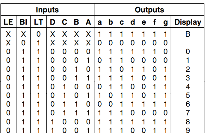
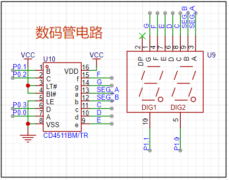
The lower four digits of port P0 are for a digital tube display, and the higher four digits are for LED
digital tubes . The circuit
uses a CD4511 to drive the digital tubes; the CD4511 is a BCD code encoder. The enable pins are already connected; only the microcontroller pins need to be controlled
to output the corresponding values. For
the LEDs,
an SS8550 PNP transistor is used to enable the LED

REG light .
Three pins of the microcontroller control different colored lights, mixing red, green, and blue to emit different colors. For

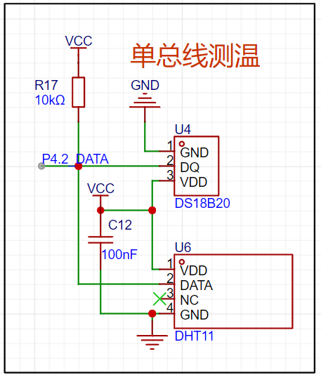
single-bus temperature measurement,
both are common sensors: the DS18B20 is a temperature sensor, and the DHT11 is a temperature and humidity sensor.
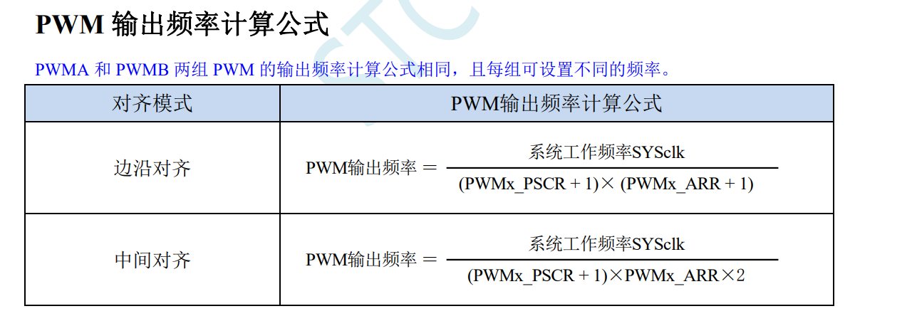
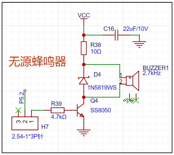
The passive buzzer circuit
requires a specific frequency electrical signal to drive it; different frequencies produce different sounds.
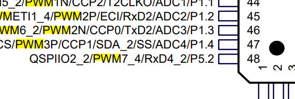
The P52 pin can be set to PWM mode, making driving convenient.
Pin headers and jumpers are used to control the buzzer's on/off state.
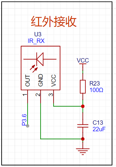
The infrared receiving circuit
uses infrared light, an electromagnetic wave with a frequency between microwaves and visible light, and a wavelength between 1 mm and 760 nanometers (nm). It is invisible light with a frequency lower than red light. The receiver uses an infrared diode, utilizing the photoelectric effect, filtering, and power amplification to form a digital signal capable of carrying a signal.
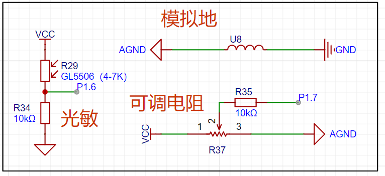
A 555 timer
adjustable resistor is used to adjust the frequency of the 555 timer. Pin P34 can be configured for external input counting .


485 communication
allows for external communication using a 485 chip. P50 and P51 are the microcontroller's serial ports .

The ADC circuit
uses a photoresistor and adjustable resistor to divide the voltage, which is then read by the microcontroller's ADC.
A copper plate in the lower right corner of the PCB is used for analog ground.
External device interfaces
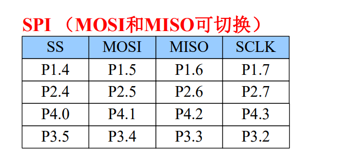
can be used to connect various sensors. The microcontroller's MOSI/MISO

interface
can be switched; using P32/P33 allows for both IIC and SPI interfaces. While mine is compatible with various screen connections, IIC communication requires writing the timing code yourself.
However, there are many online resources available, and development is not difficult.
III. Demonstration of Some Physical Functions:
Downloading
can be completed using only a Type-C cable, without the need for driver installation, which is very convenient.
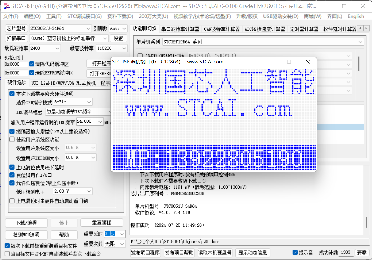
Download Process:
1. Open the STCAI-ISP software.
2. Select the corresponding chip model
. 3. Select the HEX file to download.
4. Set the IRC frequency.
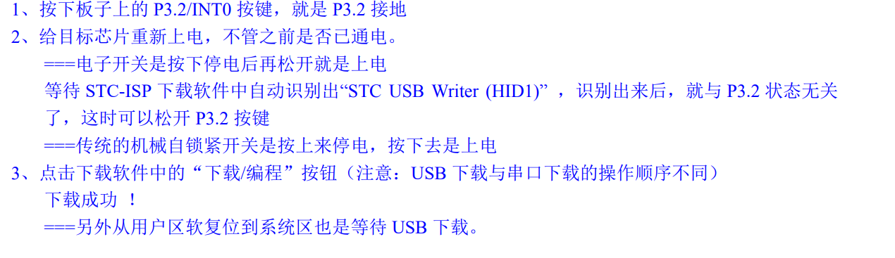
5. Press and hold the P32 pin (do not release), then press the enable button on the voltage regulator chip to power off, and then release the enable button to power on.
At this point, you can see that (HID1) STC-USB Writer 6 has been detected.

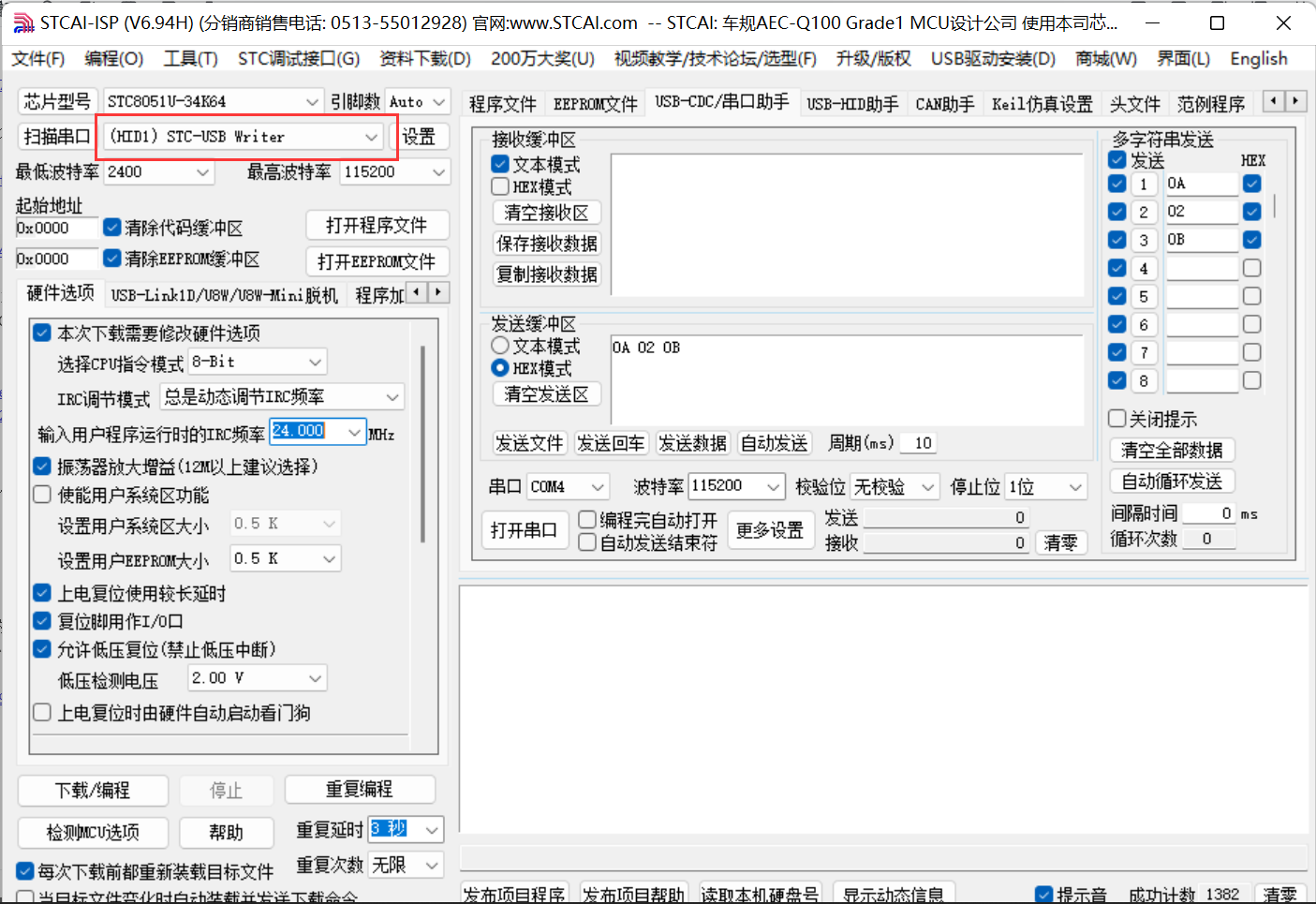
Finally, click download. For
LINK tool download,
I'm using a USB to dual serial port downloader.
After connecting the tool to the pin header on the development board, you can click download in STCAI-ISP, which is very convenient.


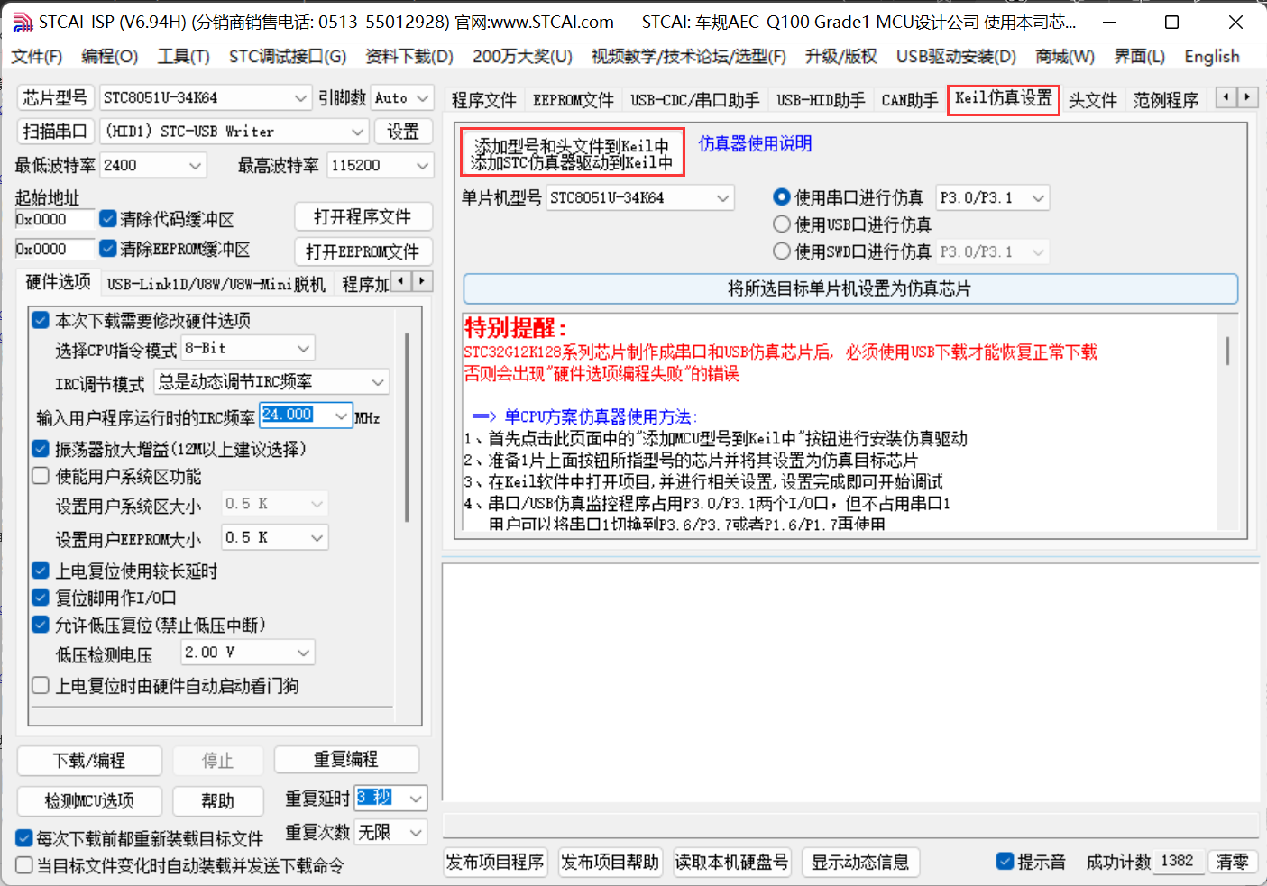
Environment setup:
1. You need to add the STC header file first. Use the STCAI-ISP software to add
the file. The add path is the KEIL installation path.
2. Create a KEIL project. Select STC to find this chip (you can choose 8-bit or 32-bit).
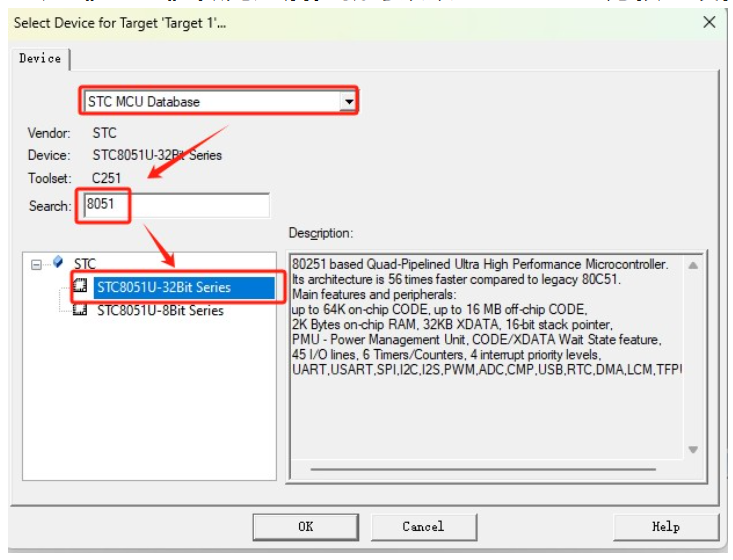
3. Select the storage mode.


4. Finally, generate a HEX file for burning
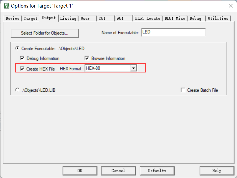
STCAI-ISP
. STCAI-ISP is a very useful tool with many other functions besides downloading,
such as serial port assistant, baud rate calculation, timer calculation, software delay calculation, etc.
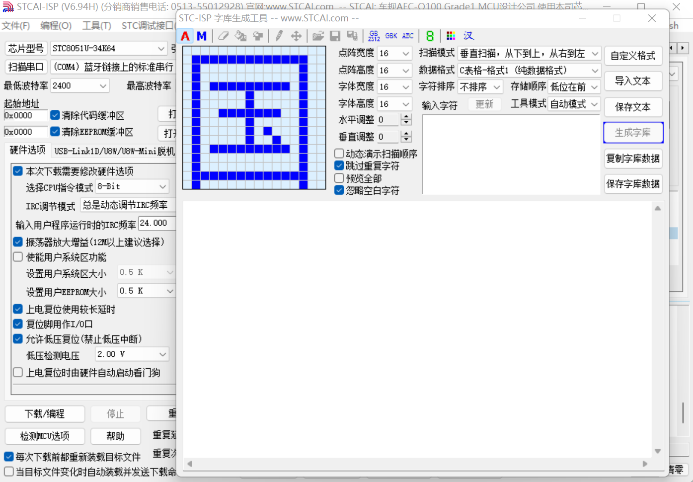
Here, I use the I/O port configuration tool for pin configuration. The configured code is directly placed in the main function for initialization,
and it's ready to use, which is very convenient.

LED & Digital Tube
REG
OLED refresh rate is very fast.


 京公网安备 11010802033920号

 KZ1J101KS


