I. Introduction
This lesson will demonstrate how to build a small smartphone using the JLCPCB Taishanpai interface.
The Taishanpai's MIPI and touchscreen interfaces are connected to the MIPI and touchscreen interfaces on a 3.1-inch screen via an adapter board, with an audio interface also provided.

Figure 1-1 shows the replica result .
The project uses the PD induction board included with the Taishanpai to provide 9V power to the board. A CH340 module is connected to the UART interface on the Taishanpai to view system operating information.
II. Hardware Related
2.1 Power Supply Interface
The power supply comes from the Taishanpai's MIPI and touchscreen interfaces, and there are two types: MIPI_DSI_VCC_LED+/-, and VCC_3V3 and GND. MIPI_DSI_VCC_LED provides power to the backlight via the MIPI interface, while 3V3 is a universal power supply. We need to power the backlight. The backlight driver circuit on the Taishanpai board has an IOUT value of 0.2V/R, resulting in IOUT = 0.2V/1.8≈110mA. However, this 3.1-inch screen can only support a maximum backlight current of 25mA. Directly connecting it to the screen poses a risk of screen burn-in or overheating. In actual testing, using the Taishanpai backlight power supply resulted in the screen becoming extremely hot. Therefore, we primarily use a 3V3 power supply.

Figure 2-1 shows the Taishanpai MIPI interface,

and Figure 2-2 shows the Taishanpai touch interface.
2.2 Backlight Circuit
The backlight circuit consists of two paths: the first is output from the Taishanpai board (pin name: MIPI_DSI_VCC_LED+/-), and the second is the onboard backlight driver output (pin name: I2C_DSI_VCC_LED+/-). The selection is achieved through four 0-ohm resistors. We default to using the onboard backlight driver power supply, i.e., omitting R1 and R2 and using R3 and R4 (zero-ohm resistors).
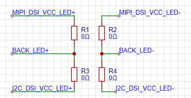
Figure 2-3 shows the backlight selection circuit
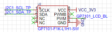
board. The backlight power supply uses the SY7201 DC-DC boost driver chip, which requires PWM to drive and determine the output voltage. The driver chip's PWM is generated by the GP7101 analog-to-digital converter chip, whose I2C interface is connected to the touchscreen interface's I2C interface, eliminating the need for additional I2C interfaces on the Taishanpai circuit board. The specific principle is as follows:
L1, D1, and C2 form a BOOST boost circuit, utilizing the inductor's energy storage characteristics for voltage boosting. R5 and R6 are sampling resistors. As seen in the chip datasheet's pin definitions, we can control the chip's output current by adjusting the resistor values. Therefore, a 10-ohm resistor is sufficient to ensure a 20mA output current. We can either place one of these resistors or two 20-ohm resistors in parallel. Drawing multiple resistors in parallel provides redundancy for actual component soldering. Meanwhile, the input pins are designed with pull-up/pull-down resistors. Only one resistor needs to be soldered to pull the pin up or down; in this case, a pull-down resistor is used.

Figure 2-4 Backlight Driver
Circuit;
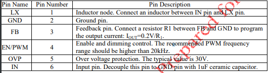
Figure 2-3 Backlight Adjustment Circuit; Figure 2-5 SY7201ABC Chip Manual Pin Definitions.
2.3 Screen-Related Interfaces
The screen used here is a 3.1-inch LCD display from Shenzhen Daxian Weiye Technology Co., Ltd. (click the link). Their documentation describes the screen interfaces; details can be found in the corresponding document (D310T9362V1 SPEC.pdf in the attachment) or sections 1.1.1 and 1.1.2 of the open-source documentation.
The touchscreen uses the I2C interface, as well as touch reset and touch interrupt trigger pins; these can also be found in sections 1.1.3 and 1.1.4 of the open-source documentation.
2.4 The audio interface
connects directly to the Taishanpai interface; see section 1.3 of the documentation for details.
2.5 Welding Precautions:
Welding the mounting brackets is relatively difficult. Refer to the welding video on Bilibili: BV19i421y7Hv.
During the welding process, R1, R2, R5, and R7 should not be welded.
III. Software Related:
Here we need to enable the MIPI device tree driver in the device tree (MIPI and EDP screens are mutually exclusive), add the backlight driver, touchscreen driver, and debug screen parameters. We can also achieve personalized effects by changing the boot logo and animation during system compilation. From a debugging perspective, we can first add the backlight driver to illuminate the backlight, then add screen parameters, and finally add the touchscreen. After debugging the screen parameters, we can directly use the Android system and debug screen parameters without needing other signal feedback to judge the touchscreen effect. (This part is under study; detailed effect diagrams will be added later.)
3.1 Adding Backlight Driver
to Debug the Screen We usually turn on the backlight first. If we are using the Taishanpai backlight circuit, we can directly use the default backlight PWM driver in the code. However, to protect the screen backlight, we choose to use the onboard backlight circuit on the expansion board to power the 3.1-inch screen backlight. The PWM pin of the onboard backlight circuit on the expansion board is implemented through the GP7101 I2C to PWM chip. Therefore, we need to write a GP7101 driver. From the schematic diagram, we can see that the GP7101 and the touch screen are connected to the I2C. From the datasheet, we can know that the I2C address of the GP7101 is 0xB0. 0xB0 includes read and write bits, so we need to shift it right by one bit in the actual code, resulting in a final address of 0x58. In tspi-rk3566-dsi-v10.dtsi, add the GP7101-related device tree driver. First, reference I2C1 and add a GP7101 child node to the I2C1 node in the device tree, specifying the I2C address, maximum backlight, default backlight, etc.
Create the backlight: Generally, backlight drivers are placed in the /kernel/drivers/video/backlight directory, so we create a my_gp7101_bl directory in this path to store the Makefile and gp7101_bl.c file.
Write the Makefile: In my_gp7101_bl/Makefile, compile gp7101_bl.c into the kernel. Alternatively, you can choose to compile it as a module using obj-m. For `obj-y += gp7101_bl.o`
to take effect, the Makefile under `my_gp7101_bl` needs to be added to the Makefile in the parent directory. Therefore, we need to add `obj-y += my_gp7101_bl/` to the Makefile in the `backlight` directory
. Then, refer to Part 3 of the open-source documentation to write the corresponding file.
3.2 Debugging Screen Parameters:
Based on the datasheet and screen parameters provided by the seller, change them to the data format in the Taishanpai device tree.
3.3 Adding Touchscreen Driver:
IV. Using Demonstration Videos
4.1 Setup (Demonstration Video 1 is used in the attachment)
4.2 Basic Usage (Demonstration Video 2 is used in the attachment)


 京公网安备 11010802033920号

 C1210C103D8UAC


