I. Chip Introduction
The XR32F429 is based on a high-performance ARM Cortex-M4F 32-bit RISC core with a maximum clock speed of 192MHz. The Cortex-M4F core features a single-precision floating-point unit (FPU) containing all ARM single-precision data processing instructions and data types. It also implements a memory protection unit (MPU) for application security. It supports integrated 832KB SRAM and 2MB Flash ROM. It also includes numerous peripherals, including UART, TWI, SPI, I2S, DMIC, PWM, IrDA (T/R), CSI, SDIO, and an auxiliary ADC.
The chip features
an integrated high-performance ARM Cortex-M4F core, equipped with 832KB SRAM and 16Mbit Flash. It also
integrates a hardware encryption/decryption engine to ensure secure data transmission and storage
. The chip boasts a high degree of integration, featuring a rich interface
platform including UART, SPI, I2C, PWM, ADC, SDIO, IrDA, I2S, DMIC, and CSI.
The ARM Cortex-M4F core operates at a maximum frequency of 192MHz.
The built-in 832KB SRAM
supports low-power RTC mode.
It is packaged in a 2Kbit Efuse
6mm x 6mm 52pin QFN package.
The encryption/decryption engine
supports AES ECB/CBC/CTR, 128/192/256-bit keys
, DES/3DES
, and MD5/SHA/SHA256/CRC16/CRC32/PRNG.
Peripherals include
2 SPI channels, 3 UART channels, 2 I2C channels, 1 SDIO channel, and IrDA.
8-channel PWM, 8-channel ADC, several GPIOs ,
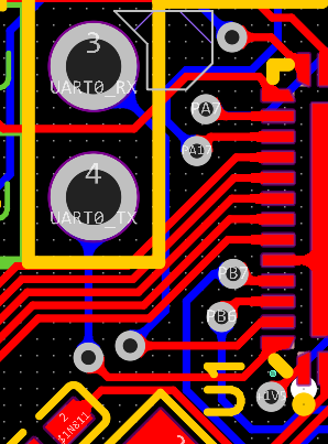
1xI2S, 1xDMIC, 1xCSI. Single power supply input, wide voltage range 2.7V-5.5V. Supports integrated 200mA 3.3V LDO for peripheral power supply. Built-in DC-DC and LDO for internal circuit use. Supports low power detection. Supports system shutdown/sleep wake-up. 24MHz XTAL 32768 low-frequency clock. Other operating temperatures: -40~85℃, storage temperature: -40~135℃. ESD HBM ±4000V, CDM ±800V. II. Project Introduction 1. Schematic Design Special attention needs to be paid to the PB2 and PB3 pins in the schematic diagram. These two pins are used as download buttons and need to be shorted across R9 during download. The XR871 Quick Start Guide details the download process: Before downloading firmware, ensure the target device is in upgrade mode. There are several ways to enter upgrade mode: 1. Unprogrammed devices (no valid content on FLASH) automatically enter upgrade mode upon power-up; 2. For programmed devices that boot normally and access the console, enter the upgrade command in the console; 3. Enter upgrade mode by simultaneously setting STRAP IO PB02 and PB03 low and then RESET the device. After entering upgrade mode, release PB02 and PB03 IOs to put them in a pull-up state; 4. Short-circuit the FLASH MISO signal to GND during power-up to automatically enter upgrade mode if the system fails to boot. 2. Due to the large number of vias in the PCB design , it is recommended to check the "Confirm Production Draft" option when ordering the PCB. Pay special attention to the following vias to prevent adhesion and short circuits: (SD connector area, especially the two vias to the right of the ESD connector) (Below the UART header) Note: The QR code is printed in a designated position on the back (5*5mm). This can be changed to custom printing if needed. III. Remarks: 1. The solution is still under verification. IV. Related Materials: XR32F429C2_Datasheet_V1.2.pdf, XR32F429C2_User_Manual_V1.0.pdf , XR32 Reference Design Schematic. 7z


 京公网安备 11010802033920号

 AISC-1008-R018G-T


