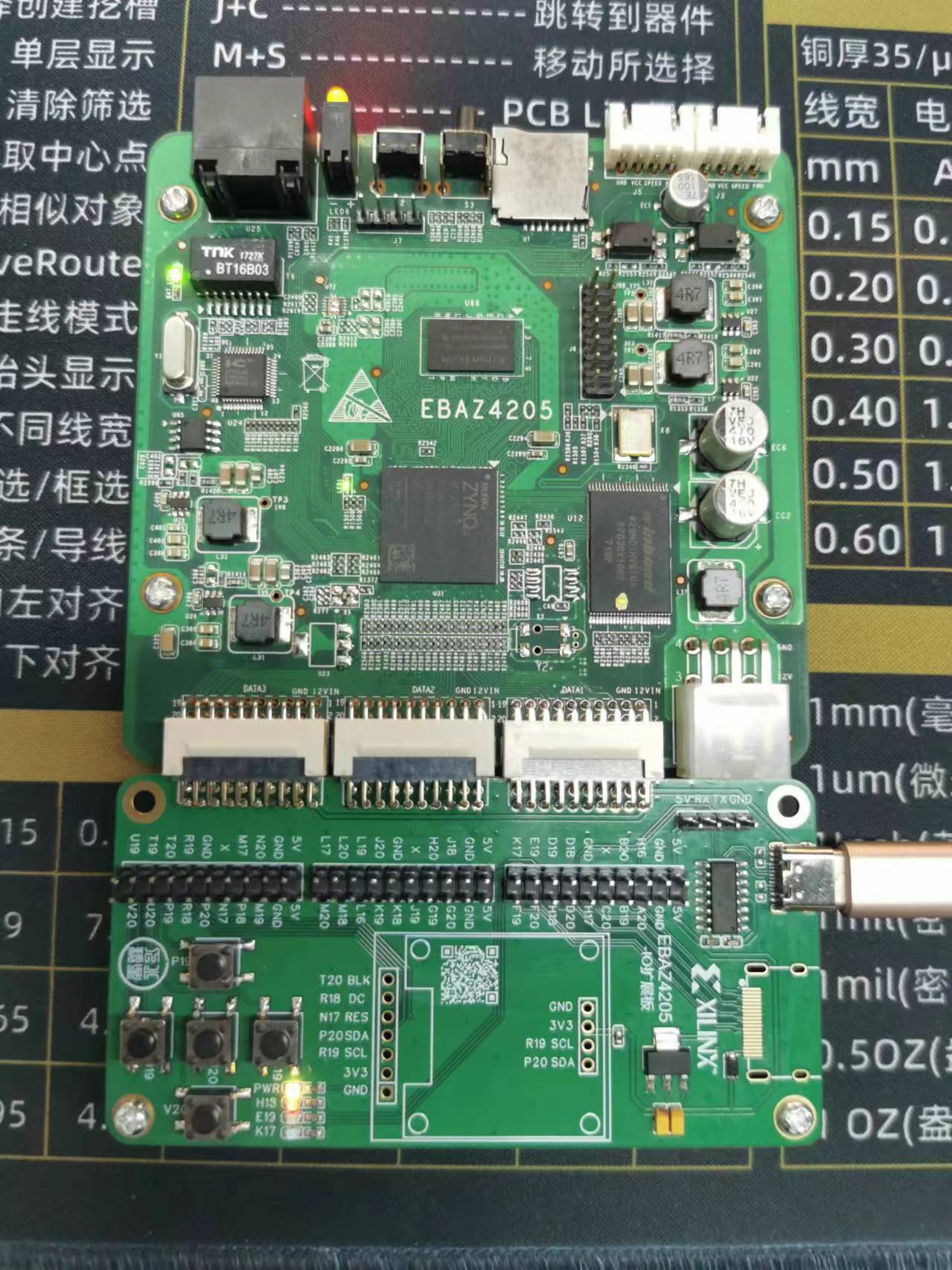
This is a simple I/O expansion board for mining slag (EBAZ4203, EBAZ4205, EBAZ4303) using
Xilinx-Zynq70Z10 .
It features simple I/O pins for control, buttons, LEDs, I2C display, and HDMI.
It is powered by Type-C and supports serial communication.
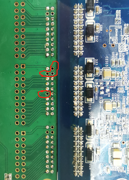
Note: The EBAZ4303 can also be used, but four pins need to be disconnected. Failure to disconnect these pins will result in a short circuit between power and ground.
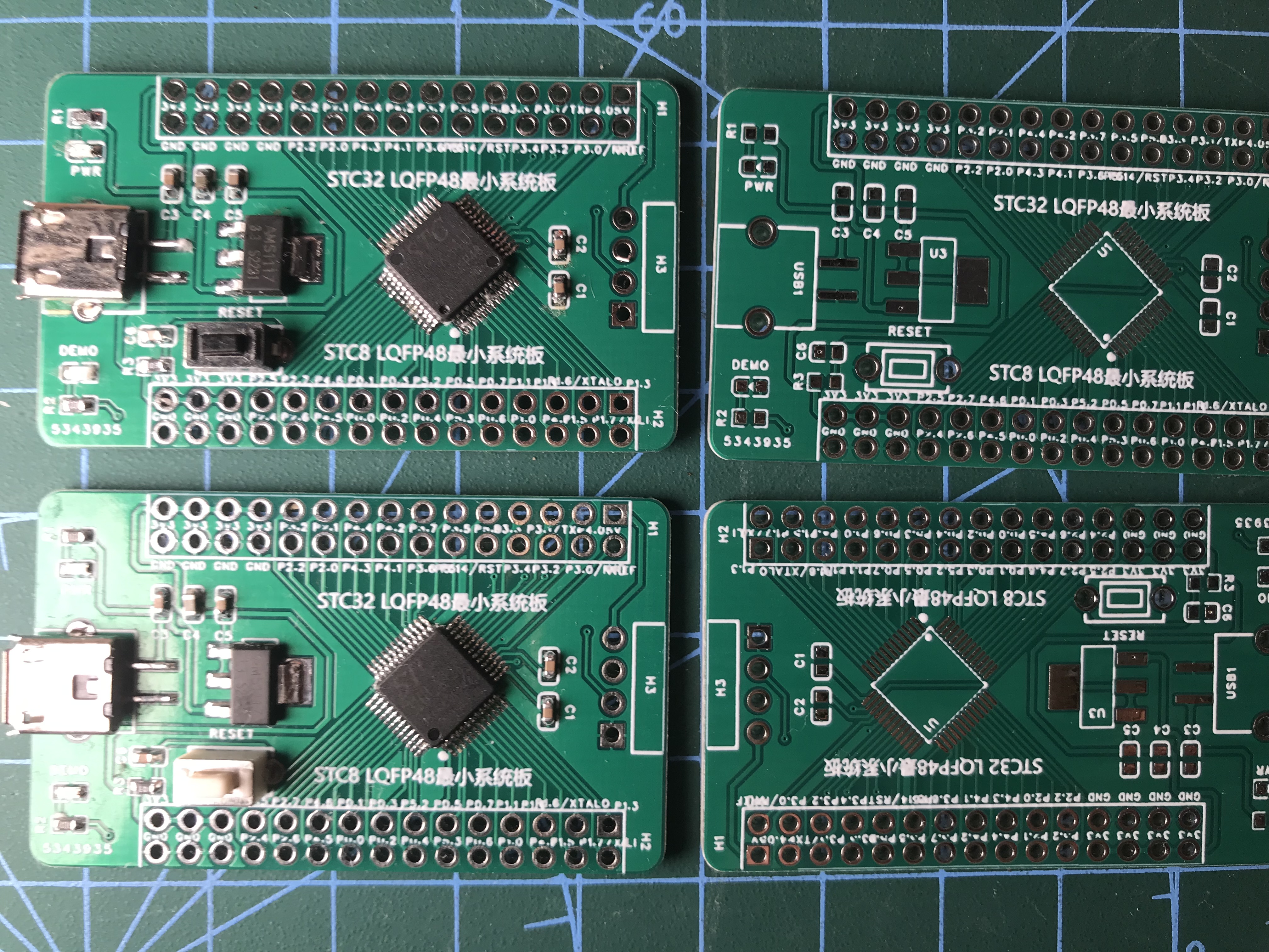
Introduction:
This project uses STC chips to design a minimum system board, compatible with STC8H8K64U and STC32G12K128 in LQFP48 packages.
Notes:
1. USB is for power only; please use serial port for downloading
. 2. VREF is not connected to 5V; a reference voltage source is required; please use a jumper cap
. 3. The silkscreen printing is not very clear; its quality depends on the silkscreen printing quality.
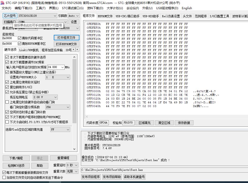
Software

download section.
2024-07-16 211621.mov
PDF_LQFP48 Minimum System Board Based on STC32 and STC8.zip
Altium-based LQFP48 minimum system board using STC32 and STC8.zip
PADS_LQFP48 Minimum System Board Based on STC32 and STC8.zip
BOM_LQFP48 Minimum System Board Based on STC32 and STC8.xlsx
93711
Traffic signal system based on STC32G12K128
A traffic signal system based on the STC32G12K128
uses the STC32G12K128 as the main control chip, red, yellow, and green LEDs as traffic lights, and digital tubes as display devices.
The STC32G12K128 microcontroller serves as the core of this traffic signal control system. Its ultra-high-speed 32-bit 8051 core (1T) provides rapid processing capabilities, making it an ideal choice for implementing complex traffic logic control. The system design considers the basic functions of traffic lights and their responsiveness to changes in traffic flow. The system uses three buttons to simulate traffic flow in different directions. These buttons are directly connected to the GPIO ports of the STC32G12K128, utilizing some of its 49 interrupt sources to achieve real-time traffic flow change detection. The MCU controls the state changes of the traffic lights based on the button inputs and preset traffic flow logic. The traffic lights use red, green, and yellow LEDs to represent different signal states. These LEDs are controlled by the MCU's GPIO ports through simple digital outputs. To ensure high brightness and long lifespan of the traffic lights, the LED driver circuit design must consider appropriate current and voltage levels. A common-anode digital tube serves as a countdown display, driven by the MCU's GPIO ports through a PNP transistor 8550, achieving high-level control. The countdown information displayed on the digital tube is based on the traffic light state and preset time parameters, providing drivers with clear signal change prompts. The system uses a Type-C interface for power supply. This design not only provides a universal and easy-to-use power supply method, but also ensures that the system can obtain stable and sufficient power.
PDF_Traffic Signaling System Based on STC32G12K128.zip
Altium-based traffic signal system using STC32G12K128.zip
PADS_Traffic Signaling System Based on STC32G12K128.zip
BOM_Traffic Signaling System Based on STC32G12K128.xlsx
93712
#Training Camp# Simple Digital Oscilloscope 1677896A Based on GD32
This is a simple digital oscilloscope developed based on the LCSC GD32E230 minimum system board.
● This project replicates the LCSC training camp's simple oscilloscope project.
● It adopts a core board + expansion board design concept.
● The core board is the LCSC GD32E230 development board.
● The expansion board includes analog front-end processing circuitry, power control circuitry, microcontroller circuitry, and human-computer interaction circuitry; surface-mount components are used in the design.
● The program uses the official example program from the training camp (I'm a civil engineering student and don't know how to code) .
Simple Digital Oscilloscope Soldering Aids_2024-4-3.html
PDF_#Training Camp# Simple Digital Oscilloscope Based on GD32 1677896A.zip
Altium_#Training Camp# Simple Digital Oscilloscope Based on GD32 1677896A.zip
PADS_#Training Camp# Simple Digital Oscilloscope Based on GD32 1677896A.zip
BOM_#Training Camp# Simple Digital Oscilloscope Based on GD32 1677896A.xlsx
93713
IP5306 Charger/Discharger
Based on the schematic diagram of 5306, a resistor for adjusting the brightness of the LED display was added, and the power input/output and charging interface were adjusted according to specific needs.
The circuit board is designed with through-hole components in mind, except for the 5306 surface-mount component. Those who prefer smaller boards and miniaturized designs should choose other options. Since this circuit board uses discrete components, those with lower power consumption requirements can choose to use 1/8W components (this circuit diagram uses 1/4W). Also, when soldering the 5306, remember to apply solder flux to the back of the chip. This circuit diagram includes two additional solder holes to enhance subsequent heat dissipation.
WeChat image_20240715160853.jpg
PDF_IP5306 Charger/Discharger.zip
Altium_IP5306 Charger/Discharger.zip
PADS_IP5306 Charger/Discharger.zip
BOM_IP5306 Charger/Discharger.xlsx
93714
Fully discrete Class AB power amplifier
Fully discrete dual-channel 400W power amplifier
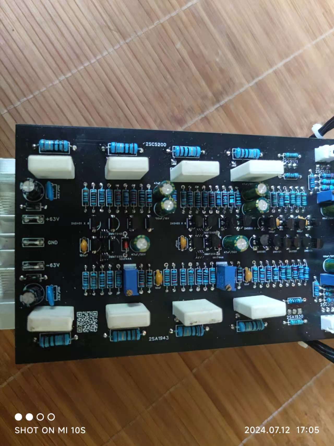
I recommend using ±48V, with one 12V protection circuit. Both share a common ground.
The overall architecture uses a three-stage structure:
the first stage is a constant current source + common-base differential input + mirror current source;
the second stage is a constant current source + single-EF dual-VAS voltage amplifier with a Vbe multiplier circuit;
the third stage is the pre-drive, drive, and power stage.
The feedback capacitor, which has a significant impact on low frequencies, has been removed. The Vbe multiplier circuit has temperature negative feedback to prevent high-temperature thermal runaway.
Theoretically, the transistors do not need to be paired, as I used integrated dual transistors. Pairing the output power transistors depends on individual budget.
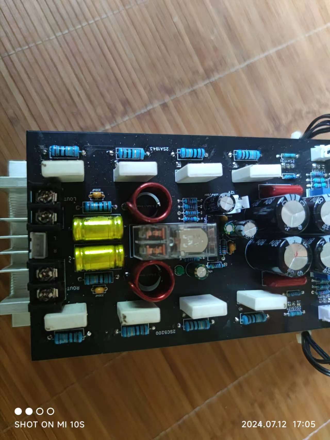
The circuit board has two output zero-adjustment potentiometers and
four 470uF potentiometers for Vbe multiplier adjustment. The F80V capacitor is placed to fill space; an external power board is actually needed, along with a minimum 10MF capacitor
for protection. The circuit uses a UPC1237.
Power is supplied via a single 12V heatsink. The power amplifier uses a heatsink with a 280mm hole
drilled in the top and bottom XH2.54 connectors. Two 10k thermistors are then screwed onto the heatsink.
Two hollow inductors are simply wound ten times with a pen.
The relay model is written on the PCB.
The power input uses 6.3mm cold-pressed terminals. Square wave testing on July 12
, 2024
, yielded unsatisfactory results due to the use of a large Miller capacitor and insufficient first-stage current.
Voltage: Dual 12V. Input: 5V square wave. Output: 3-ohm cement resistor

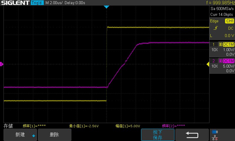
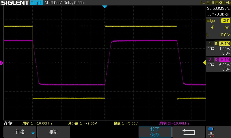

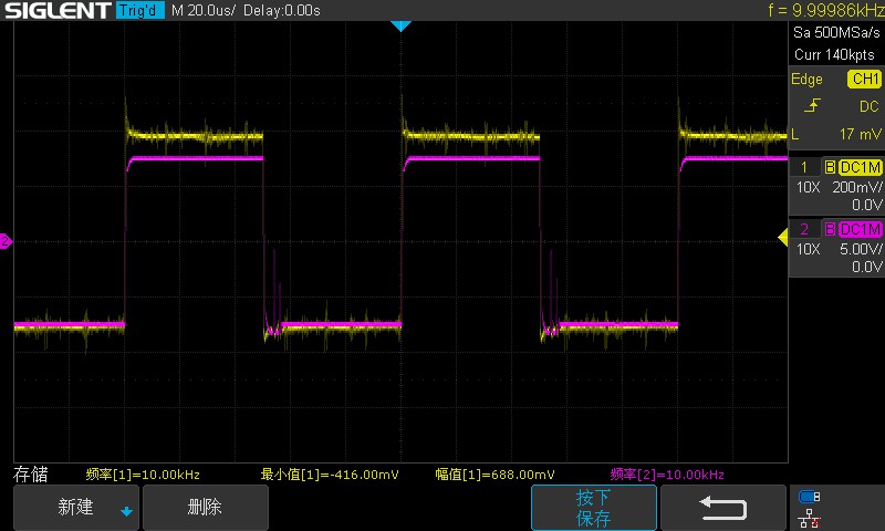
. For conservative reasons, I only applied 3V to the 6 PN junctions. Miller capacitor: 470pF. On
July 17, 2024,
I changed R1 and R53 to 150 ohms, R6, R7, R57, and R58 to 120 ohms, and R8, R9, R59, and R60 to 51 ohms. After changing C8 and C15 to 100pF, the slew rate significantly improved.
The differential input stage current is around 4mA, and the voltage amplification stage current is around 10mA.
PDF_Fully Discrete Class AB Power Amplifier.zip
Altium_All Discrete Class AB Amplifier.zip
PADS_All Discrete Class AB Power Amplifiers.zip
BOM_Fully Discrete Class AB Power Amplifier.xlsx
93715
Bluetooth keypad for arcade mahjong
Bringing the electronic baseboard and Tiankaiyan from my memory home, I made my own Bluetooth keyboard for arcade mahjong games.
Game resources can be downloaded from https://pad.gm.ws
Mahjong_BOM_Board1_Schematic1_2024-07-11.xlsx
mahjong on.STL
mahjong下.STL
July 11.mp4
mahjongkeyboard.ino
PDF_Arcade Mahjong Bluetooth Keyboard.zip
Altium_Arcade Mahjong Bluetooth Keyboard.zip
PADS_Arcade Mahjong Bluetooth Keyboard.zip
BOM_Bluetooth Keyboard for Arcade Mahjong.xlsx
93716
electronic


 京公网安备 11010802033920号

 1600SGH3009G2DB


