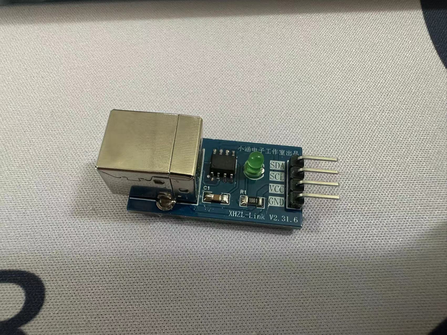
 Image of back of the product: Image of back of the product:
  Image of usage:
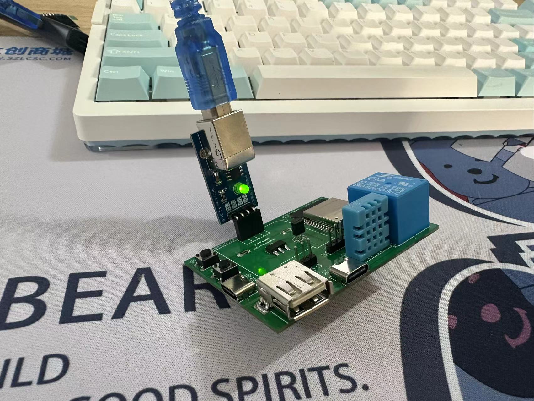
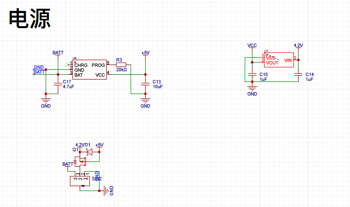 This project uses dual power supply of TYPE-C and battery.
  The step-down chip is XC6206P332MR, which is small in size and requires few external components .
 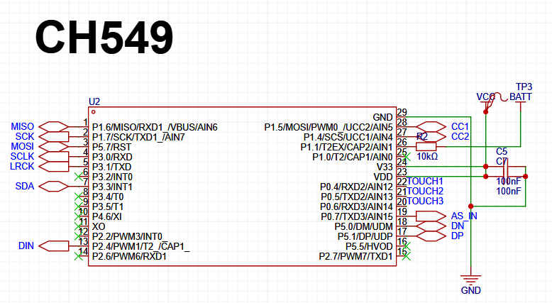 This project uses CH549F as the main controller, which has low power consumption, small size, rich I/O, and low cost.
 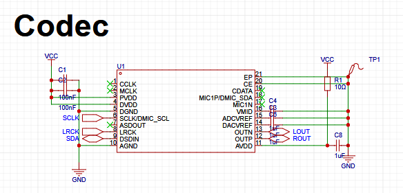 This project uses the ES8311 as the decoder, which is compact and feature-rich.
  This project uses the CH442E as the MUX, which can switch between audio output and main control USB connection depending on the power input status.

All reference designs on this site are sourced from major semiconductor manufacturers or collected online for learning and research. The copyright belongs to the semiconductor manufacturer or the original author. If you believe that the reference design of this site infringes upon your relevant rights and interests, please send us a rights notice. As a neutral platform service provider, we will take measures to delete the relevant content in accordance with relevant laws after receiving the relevant notice from the rights holder. Please send relevant notifications to email: bbs_service@eeworld.com.cn.
It is your responsibility to test the circuit yourself and determine its suitability for you. EEWorld will not be liable for direct, indirect, special, incidental, consequential or punitive damages arising from any cause or anything connected to any reference design used.
Supported by EEWorld Datasheet
EEWorld
subscription
account

EEWorld
service
account

Automotive
development
community

Robot
development
community

About Us Customer Service Contact Information Datasheet Sitemap LatestNews


Room 1530, 15th Floor, Building B,
No.18 Zhongguancun Street,
Haidian District,
Beijing, Postal Code: 100190
China
Telephone: 008610 8235 0740
 京公网安备 11010802033920号

 51721-10012807AALF


